mirror controls DODGE RAM 2003 Service Repair Manual
[x] Cancel search | Manufacturer: DODGE, Model Year: 2003, Model line: RAM, Model: DODGE RAM 2003Pages: 2895, PDF Size: 83.15 MB
Page 582 of 2895

DOOR LOCK MOTOR
DESCRIPTION
The lock mechanisms are actuated by a reversible
electric motor mounted within each door. The power
lock motors are integral to the door latch units.
The power lock motors cannot be adjusted or
repaired and, if faulty or damaged, the door latch
unit must be replaced.
OPERATION
The door lock motors are controlled by the instru-
ment cluster. A positive and negative battery connec-
tion to the two motor terminals will cause the motor
to move in one direction. Reversing the current will
cause the motor to move in the opposite direction.
DIAGNOSIS AND TESTING - DOOR LOCK
MOTOR
The most reliable, efficient, and accurate means to
diagnose the power lock system requires the use of a
DRBIIItscan tool and the proper Diagnostic Proce-
dures manual. The DRBIIItscan tool can provide
confirmation that the PCI data bus is functional, that
all of the electronic modules are sending and receiv-
ing the proper messages on the PCI data bus, and
that the power lock motors are being sent the proper
hard wired outputs by the door modules for them to
perform their power lock system functions.
Refer to the appropriate wiring information. The
wiring information includes wiring diagrams, proper
wire and connector repair procedures, details of wire
harness routing and retention, connector pin-out
information and location views for the various wire
harness connectors, splices and grounds.
DRIVER DOOR MODULE
DESCRIPTION
A Driver Door Module (DDM) is used on all models
equipped with power locks, power windows, and
power mirrors. The DDM houses the following
switches:
²Power Lock Switch- The DDM includes a
two-way, momentary, resistor multiplexed switch to
control the power lock system.
²Power Mirror Selector Switch- A three-posi-
tion rocker switch in the DDM selects the right or
left power mirror for adjustment, or turns the power
mirror system Off.
²Power Mirror Adjustment Switches- Four
momentary, arrowhead shaped, directional switches
allow the driver to adjust the selected power mirror
in the Up, Down, Right, or Left directions.²Power Window Lockout Switch- A two-way,
latching, push-button switch in the DDM allows the
vehicle operator to lock out the power window
switches on each passenger door so that the passen-
ger door power windows may be operated only from
the master switches in the DDM.
²Power Window Switches- The DDM houses a
two-way, momentary power window switch for the
driver side front door. This switch also has a second
detent in the Down direction and internal circuitry to
provide an Auto-Down feature for the driver side
front door power window. In addition to the power
window switch for its own door, the DDM houses
individual master switches for each passenger door
power window.
The DDM also incorporates several green Light-
Emitting Diodes (LEDs) that illuminate the power
lock and power window switch paddles, and the
power mirror switch directional buttons to improve
switch visibility in dark ambient lighting conditions.
The DDM cannot be adjusted or repaired and, if
faulty or damaged, the entire DDM unit must be
replaced.
OPERATION
The Driver Door Module (DDM) combines a power
lock switch, a driver power window switch with an
Auto-down feature, master switches for each passen-
ger door power window, a power window lockout
switch, a power mirror selector switch, and four
power mirror adjustment switches in a single unit.
The switches in the DDM can be diagnosed using
conventional diagnostic tools and methods.
Power Lock Switch
The DDM power lock switch circuitry is connected
in series between ground and the driver door switch
mux input of the instrument cluster. Each power lock
switch position (Lock, Unlock, and Neutral) provides
a different resistance value to the instrument cluster
input, which allows the instrument cluster to sense
the switch position. Based upon the power lock
switch input, the instrument cluster controls the bat-
tery and ground feed outputs to the individual power
lock motors to lock or unlock the door latches. The
Light-Emitting Diode (LED) in the DDM power lock
switch is connected to battery current through the
power window circuit breaker in the Integrated
Power Module (IPM) on a fused ignition switch out-
put (run-acc) circuit so that the switch will be illumi-
nated whenever the ignition switch is in the On or
Accessory positions.
Power Window Switches
The DDM power window switch circuitry is con-
nected to battery current through a circuit breaker in
DRPOWER LOCKS 8N - 5
Page 583 of 2895

the Integrated Power Module (IPM) on a fused igni-
tion switch output (run-acc) circuit so that the power
windows will operate whenever the ignition switch is
in the On or Accessory positions. Each two-way,
momentary master passenger power window switch
in the DDM provides battery current and ground to
the individual power window switches on each pas-
senger door so that the power window switch controls
the battery current and ground feeds to its respective
power window motor. The DDM switch for the driver
side front door power window is labeled ªAutoº and
includes an auto-down feature. When this switch is
depressed to a second momentary detent position and
released, the driver door power window is automati-
cally operated through an internal circuit and relay
to its fully lowered position. The Auto-down event is
cancelled if the switch paddle is depressed a second
time in either the Up or Down direction. When the
two position window lockout switch in the DDM is
depressed and latched in the lockout position, the
battery current feed to each of the individual passen-
ger power window switches is interrupted so that the
passenger door power windows can only be operated
from the master switches in the DDM. The window
lockout switch also controls the battery current feed
for the LED in each passenger power window switch
so that the switch will not be illuminated when it is
locked out.
Power Mirror Switches
The DDM power mirror switch circuitry is con-
nected to battery current through a fuse in the IPM
on a fused B(+) circuit so that the power mirrors
remain operational regardless of the ignition switch
position. A rocker type selector switch has three posi-
tions, one to select the right mirror, one to select the
left mirror, and a neutral Off position. After the right
or left mirror is selected, one of four directional but-
tons is depressed to move the selected mirror Up,
Down, Right or Left. The DDM power mirror switch
circuitry controls the battery current and ground
feeds to each of the four (two in each mirror head)
power mirror motors. The Light-Emitting Diode
(LED) in the DDM power mirror switch is connected
to battery current through the power window circuit
breaker in the IPM on a fused ignition switch output
(run-acc) circuit so that the switch directional but-
tons will be illuminated whenever the ignition switch
is in the On or Accessory positions.DIAGNOSIS AND TESTING - DRIVER DOOR
MODULE
The Light-Emitting Diode (LED) illumination
lamps for all of the Driver Door Module (DDM)
power window, power lock, and power mirror
switches receive battery current through the power
window circuit breaker in the Integrated Power Mod-
ule (IPM). If all of the LEDs are inoperative in the
DDM, be certain to diagnose the power window sys-
tem before replacing the switch unit. (Refer to 8 -
ELECTRICAL/POWER WINDOWS - DIAGNOSIS
AND TESTING). If only one LED in the DDM is
inoperative, replace the faulty DDM. If the driver
side front door power window operates in a normal
manner, but the Auto-Down feature is inoperative,
replace the faulty DDM. Refer to the appropriate wir-
ing information. The wiring information includes wir-
ing diagrams, proper wire and connector repair
procedures, details of wire harness routing and
retention, connector pin-out information and location
views for the various wire harness connectors, splices
and grounds.
(1) Disconnect and isolate the battery negative
cable. Remove the DDM from the door trim panel.
Disconnect the door wire harness connectors for the
DDM from the DDM connector receptacles.
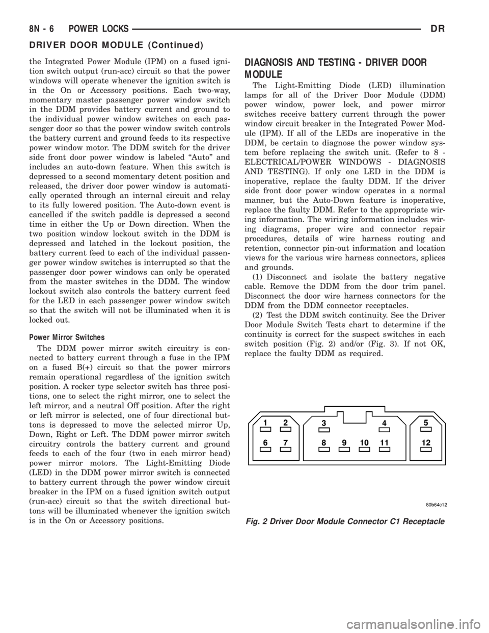
(2) Test the DDM switch continuity. See the Driver
Door Module Switch Tests chart to determine if the
continuity is correct for the suspect switches in each
switch position (Fig. 2) and/or (Fig. 3). If not OK,
replace the faulty DDM as required.
Fig. 2 Driver Door Module Connector C1 Receptacle
8N - 6 POWER LOCKSDR
DRIVER DOOR MODULE (Continued)
Page 2789 of 2895

for relay terminal 86 with the ignition switch in the
On position. If OK, go to Step 5. If not OK, repair the
open circuit to the fuse in the junction block as
required.
(5) The coil ground terminal cavity (85) is switched
to ground through the Powertrain Control Module
(PCM). There should be continuity between this cav-
ity and the A/C compressor clutch relay control cir-
cuit cavity of the PCM wire harness connector C
(gray) at all times. If not OK, repair the open circuit
as required.
REMOVAL
(1) Disconnect and isolate the battery negative
cable.
(2) Remove the cover from the Power Distribution
Center (PDC).
(3) Refer to the label on the PDC for compressor
clutch relay identification and location.
(4) Unplug the compressor clutch relay from the
PDC.
INSTALLATION
(1) Install the compressor clutch relay by aligning
the relay terminals with the cavities in the PDC and
pushing the relay firmly into place.
(2) Install the PDC cover.
(3) Connect the battery negative cable.
(4) Test the relay operation.
A/C HEATER CONTROL
DESCRIPTION
The A/C heater system uses a seriers of electrical
controls. These controls provide the vehicle operator
with a number of setting options to help control the
climate and comfort within the vehicle. Refer to the
owner's manual in the vehicle glove box for more
information on the features, use, and suggested oper-
ation of these controls.
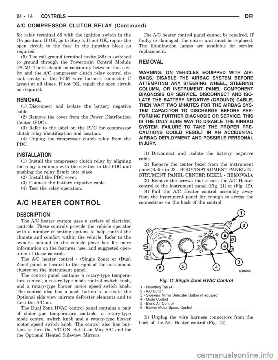
The A/C heater control - (Single Zone) or (Dual
Zone) panel is located to the right of the instrument
cluster on the instrument panel.
The control panel contains a rotary-type tempera-
ture control, a rotary-type mode control switch knob,
and a rotary-type blower motor speed switch knob.
The control also has a push button to activate the
Optional side view mirrors defroster elements and to
turn the A/C on.
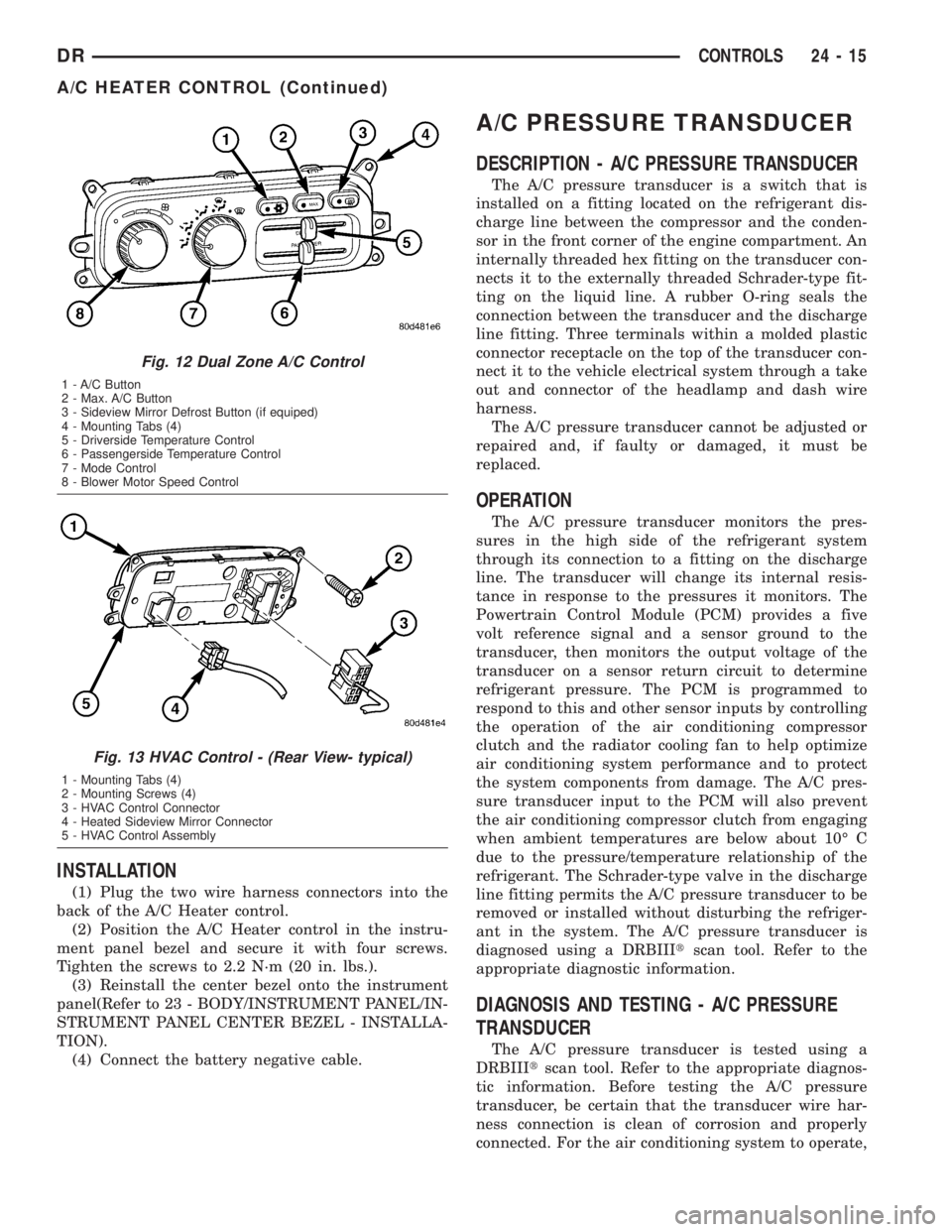
The Dual Zone HVAC control panel contains a pair
of slider-type temperature controls, a rotary-type
mode control switch knob and a rotary-type blower
motor speed switch knob. The control also has but-
tons to turn the A/C ON, Set it on Max A/C and for
the Optional Heated Sideview Mirrors.The A/C heater control panel cannot be repaired. If
faulty or damaged, the entire unit must be replaced.
The illumination lamps are available for service
replacement.
REMOVAL
WARNING: ON VEHICLES EQUIPPED WITH AIR-
BAGS, DISABLE THE AIRBAG SYSTEM BEFORE
ATTEMPTING ANY STEERING WHEEL, STEERING
COLUMN, OR INSTRUMENT PANEL COMPONENT
DIAGNOSIS OR SERVICE. DISCONNECT AND ISO-
LATE THE BATTERY NEGATIVE (GROUND) CABLE,
THEN WAIT TWO MINUTES FOR THE AIRBAG SYS-
TEM CAPACITOR TO DISCHARGE BEFORE PER-
FORMING FURTHER DIAGNOSIS OR SERVICE. THIS
IS THE ONLY SURE WAY TO DISABLE THE AIRBAG
SYSTEM. FAILURE TO TAKE THE PROPER PRE-
CAUTIONS COULD RESULT IN AN ACCIDENTAL
AIRBAG DEPLOYMENT AND POSSIBLE PERSONAL
INJURY.
(1) Disconnect and isolate the battery negative
cable.
(2) Remove the center bezel from the instrument
panel(Refer to 23 - BODY/INSTRUMENT PANEL/IN-
STRUMENT PANEL CENTER BEZEL - REMOVAL).
(3) Remove the screws that secure the A/C Heater
control to the instrument panel (Fig. 11) or (Fig. 12).
(4) Pull the A/C Heater control assembly away
from the instrument panel far enough to access the
connections on the back of the control.
(5) Unplug the wire harness connectors from the
back of the A/C Heater control (Fig. 13).
Fig. 11 Single Zone HVAC Control
1 - Mounting Tab (4)
2 - A/C Button
3 - Sideview Mirror Defroster Button (if equiped)
4 - Mode Control
5 - Blend Air Control
6 - Blower Motor Speed Control
24 - 14 CONTROLSDR
A/C COMPRESSOR CLUTCH RELAY (Continued)
Page 2790 of 2895

INSTALLATION
(1) Plug the two wire harness connectors into the
back of the A/C Heater control.
(2) Position the A/C Heater control in the instru-
ment panel bezel and secure it with four screws.
Tighten the screws to 2.2 N´m (20 in. lbs.).
(3) Reinstall the center bezel onto the instrument
panel(Refer to 23 - BODY/INSTRUMENT PANEL/IN-
STRUMENT PANEL CENTER BEZEL - INSTALLA-
TION).
(4) Connect the battery negative cable.
A/C PRESSURE TRANSDUCER
DESCRIPTION - A/C PRESSURE TRANSDUCER
The A/C pressure transducer is a switch that is
installed on a fitting located on the refrigerant dis-
charge line between the compressor and the conden-
sor in the front corner of the engine compartment. An
internally threaded hex fitting on the transducer con-
nects it to the externally threaded Schrader-type fit-
ting on the liquid line. A rubber O-ring seals the
connection between the transducer and the discharge
line fitting. Three terminals within a molded plastic
connector receptacle on the top of the transducer con-
nect it to the vehicle electrical system through a take
out and connector of the headlamp and dash wire
harness.
The A/C pressure transducer cannot be adjusted or
repaired and, if faulty or damaged, it must be
replaced.
OPERATION
The A/C pressure transducer monitors the pres-
sures in the high side of the refrigerant system
through its connection to a fitting on the discharge
line. The transducer will change its internal resis-
tance in response to the pressures it monitors. The
Powertrain Control Module (PCM) provides a five
volt reference signal and a sensor ground to the
transducer, then monitors the output voltage of the
transducer on a sensor return circuit to determine
refrigerant pressure. The PCM is programmed to
respond to this and other sensor inputs by controlling
the operation of the air conditioning compressor
clutch and the radiator cooling fan to help optimize
air conditioning system performance and to protect
the system components from damage. The A/C pres-
sure transducer input to the PCM will also prevent
the air conditioning compressor clutch from engaging
when ambient temperatures are below about 10É C
due to the pressure/temperature relationship of the
refrigerant. The Schrader-type valve in the discharge
line fitting permits the A/C pressure transducer to be
removed or installed without disturbing the refriger-
ant in the system. The A/C pressure transducer is
diagnosed using a DRBIIItscan tool. Refer to the
appropriate diagnostic information.
DIAGNOSIS AND TESTING - A/C PRESSURE
TRANSDUCER
The A/C pressure transducer is tested using a
DRBIIItscan tool. Refer to the appropriate diagnos-
tic information. Before testing the A/C pressure
transducer, be certain that the transducer wire har-
ness connection is clean of corrosion and properly
connected. For the air conditioning system to operate,
Fig. 12 Dual Zone A/C Control
1 - A/C Button
2 - Max. A/C Button
3 - Sideview Mirror Defrost Button (if equiped)
4 - Mounting Tabs (4)
5 - Driverside Temperature Control
6 - Passengerside Temperature Control
7 - Mode Control
8 - Blower Motor Speed Control
Fig. 13 HVAC Control - (Rear View- typical)
1 - Mounting Tabs (4)
2 - Mounting Screws (4)
3 - HVAC Control Connector
4 - Heated Sideview Mirror Connector
5 - HVAC Control Assembly
DRCONTROLS 24 - 15
A/C HEATER CONTROL (Continued)