parking brake DODGE RAM 2003 Service Repair Manual
[x] Cancel search | Manufacturer: DODGE, Model Year: 2003, Model line: RAM, Model: DODGE RAM 2003Pages: 2895, PDF Size: 83.15 MB
Page 7 of 2895
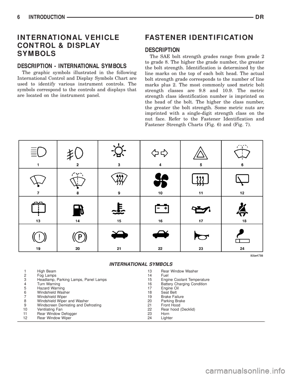
INTERNATIONAL VEHICLE
CONTROL & DISPLAY
SYMBOLS
DESCRIPTION - INTERNATIONAL SYMBOLS
The graphic symbols illustrated in the following
International Control and Display Symbols Chart are
used to identify various instrument controls. The
symbols correspond to the controls and displays that
are located on the instrument panel.
FASTENER IDENTIFICATION
DESCRIPTION
The SAE bolt strength grades range from grade 2
to grade 8. The higher the grade number, the greater
the bolt strength. Identification is determined by the
line marks on the top of each bolt head. The actual
bolt strength grade corresponds to the number of line
marks plus 2. The most commonly used metric bolt
strength classes are 9.8 and 10.9. The metric
strength class identification number is imprinted on
the head of the bolt. The higher the class number,
the greater the bolt strength. Some metric nuts are
imprinted with a single-digit strength class on the
nut face. Refer to the Fastener Identification and
Fastener Strength Charts (Fig. 6) and (Fig. 7).
INTERNATIONAL SYMBOLS
1 High Beam 13 Rear Window Washer
2 Fog Lamps 14 Fuel
3 Headlamp, Parking Lamps, Panel Lamps 15 Engine Coolant Temperature
4 Turn Warning 16 Battery Charging Condition
5 Hazard Warning 17 Engine Oil
6 Windshield Washer 18 Seat Belt
7 Windshield Wiper 19 Brake Failure
8 Windshield Wiper and Washer 20 Parking Brake
9 Windscreen Demisting and Defrosting 21 Front Hood
10 Ventilating Fan 22 Rear hood (Decklid)
11 Rear Window Defogger 23 Horn
12 Rear Window Wiper 24 Lighter
6 INTRODUCTIONDR
Page 26 of 2895
JUMP STARTING
STANDARD PROCEDURE - JUMP STARTING
WARNING: REVIEW ALL SAFETY PRECAUTIONS
AND WARNINGS IN THE BATTERY SYSTEM SEC-
TION OF THE SERVICE MANUAL. (Refer to 8 -
ELECTRICAL/BATTERY SYSTEM/BATTERY - STAN-
DARD PROCEDURE)
²DO NOT JUMP START A FROZEN BATTERY,
PERSONAL INJURY CAN RESULT.
²IF EQUIPPED, DO NOT JUMP START WHEN
MAINTENANCE FREE BATTERY INDICATOR DOT IS
YELLOW OR BRIGHT COLOR.
²DO NOT JUMP START A VEHICLE WHEN THE
BATTERY FLUID IS BELOW THE TOP OF LEAD
PLATES.
²DO NOT ALLOW JUMPER CABLE CLAMPS TO
TOUCH EACH OTHER WHEN CONNECTED TO A
BOOSTER SOURCE.
²DO NOT USE OPEN FLAME NEAR BATTERY.
²REMOVE METALLIC JEWELRY WORN ON
HANDS OR WRISTS TO AVOID INJURY BY ACCI-
DENTAL ARCING OF BATTERY CURRENT.
²WHEN USING A HIGH OUTPUT BOOSTING
DEVICE, DO NOT ALLOW BATTERY VOLTAGE TO
EXCEED 16 VOLTS. REFER TO INSTRUCTIONS
PROVIDED WITH DEVICE BEING USED.
FAILURE TO FOLLOW THESE INSTRUCTIONS MAY
RESULT IN PERSONAL INJURY.
CAUTION: When using another vehicle as a
booster, do not allow vehicles to touch. Electrical
systems can be damaged on either vehicle.
TO JUMP START A DISABLED VEHICLE:
(1) Raise hood on disabled vehicle and visually
inspect engine compartment for:
²Battery cable clamp condition, clean if necessary.
²Frozen battery.
²Yellow or bright color test indicator, if equipped.
²Low battery fluid level.
²Generator drive belt condition and tension.
²Fuel fumes or leakage, correct if necessary.CAUTION: If the cause of starting problem on dis-
abled vehicle is severe, damage to booster vehicle
charging system can result.
(2) When using another vehicle as a booster
source, park the booster vehicle within cable reach.
Turn off all accessories, set the parking brake, place
the automatic transmission in PARK or the manual
transmission in NEUTRAL and turn the ignition
OFF.
(3) On disabled vehicle, place gear selector in park
or neutral and set park brake. Turn off all accesso-
ries.
(4) Connect jumper cables to booster battery. RED
clamp to positive terminal (+). BLACK clamp to neg-
ative terminal (-). DO NOT allow clamps at opposite
end of cables to touch, electrical arc will result.
Review all warnings in this procedure.
(5) On disabled vehicle, connect RED jumper cable
clamp to positive (+) terminal. Connect BLACK
jumper cable clamp to engine ground as close to the
ground cable attaching point as possible.
(6) Start the engine in the vehicle which has the
booster battery, let the engine idle a few minutes,
then start the engine in the vehicle with the dis-
charged battery.
CAUTION: Do not crank starter motor on disabled
vehicle for more than 15 seconds, starter will over-
heat and could fail.
(7) Allow battery in disabled vehicle to charge to
at least 12.4 volts (75% charge) before attempting to
start engine. If engine does not start within 15 sec-
onds, stop cranking engine and allow starter to cool
(15 min.), before cranking again.
DISCONNECT CABLE CLAMPS AS FOLLOWS:
²Disconnect BLACK cable clamp from engine
ground on disabled vehicle.
²When using a Booster vehicle, disconnect
BLACK cable clamp from battery negative terminal.
Disconnect RED cable clamp from battery positive
terminal.
²Disconnect RED cable clamp from battery posi-
tive terminal on disabled vehicle.
DRLUBRICATION & MAINTENANCE 0 - 13
Page 147 of 2895
REMOVAL
(1) Raise and support the vehicle.
(2) Position a lifting device under the axle.
(3) Secure axle to device.
(4) Remove wheels and tires assemblies.
(5) Remove RWAL sensor from the differential
housing.
(6) Remove brake hose at the axle junction block.
(7) Disconnect parking brake cables and cable
brackets.
(8) Remove brake calipers and rotors.
(9) Remove axle vent hose.
(10) Mark propeller shaft and companion flange
for installation alignment reference.
(11) Remove propeller shaft.
(12) Remove shock absorbers from axle.
(13) Remove U-bolets from axle.
(14) Separate the axle from the vehicle.
INSTALLATION
(1) Raise axle with lifting device and align to the
leaf spring centering bolts.
(2) Install axle U-bolts and tighten to 149 N´m
(110 ft. lbs.).
(3) Install shock absorbers to axle and tighten to
specification.
(4) Install the RWAL sensor to the differential
housing.
(5) Connect the parking brake cables and cable
brackets.
(6) Install brake rotors and calipers.
(7) Connect brake hose to the axle junction block.
(8) Install axle vent hose.
(9) Align propeller shaft and pinion companion
flange reference marks and tighten companion flange
bolts to 115 N´m (85 ft. lbs.).
(10) Install the wheels and tires.
(11) Fill differential to specifications.
(12) Remove lifting device from axle and lower the
vehicle.
ADJUSTMENTS
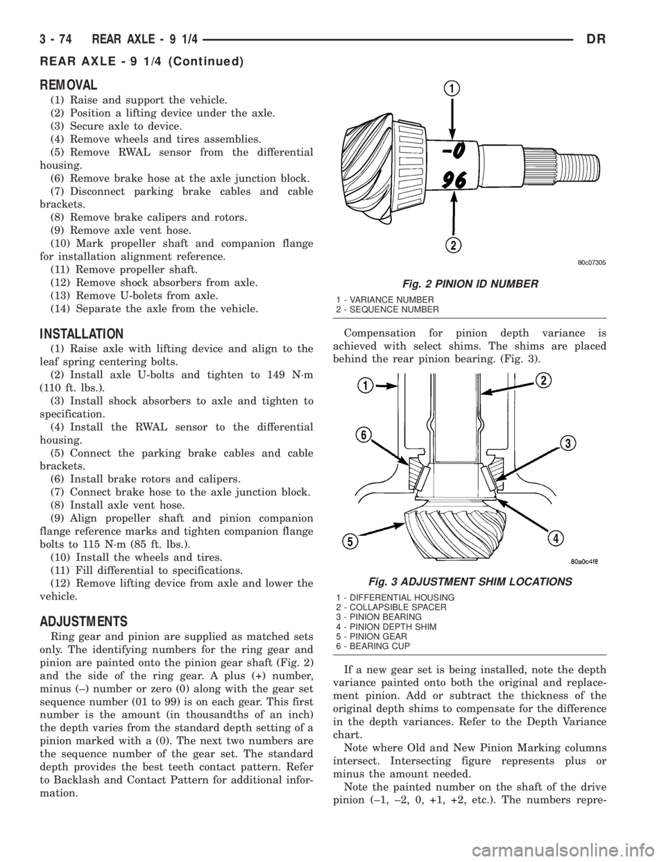
Ring gear and pinion are supplied as matched sets
only. The identifying numbers for the ring gear and
pinion are painted onto the pinion gear shaft (Fig. 2)
and the side of the ring gear. A plus (+) number,
minus (±) number or zero (0) along with the gear set
sequence number (01 to 99) is on each gear. This first
number is the amount (in thousandths of an inch)
the depth varies from the standard depth setting of a
pinion marked with a (0). The next two numbers are
the sequence number of the gear set. The standard
depth provides the best teeth contact pattern. Refer
to Backlash and Contact Pattern for additional infor-
mation.Compensation for pinion depth variance is
achieved with select shims. The shims are placed
behind the rear pinion bearing. (Fig. 3).
If a new gear set is being installed, note the depth
variance painted onto both the original and replace-
ment pinion. Add or subtract the thickness of the
original depth shims to compensate for the difference
in the depth variances. Refer to the Depth Variance
chart.
Note where Old and New Pinion Marking columns
intersect. Intersecting figure represents plus or
minus the amount needed.
Note the painted number on the shaft of the drive
pinion (±1, ±2, 0, +1, +2, etc.). The numbers repre-
Fig. 2 PINION ID NUMBER
1 - VARIANCE NUMBER
2 - SEQUENCE NUMBER
Fig. 3 ADJUSTMENT SHIM LOCATIONS
1 - DIFFERENTIAL HOUSING
2 - COLLAPSIBLE SPACER
3 - PINION BEARING
4 - PINION DEPTH SHIM
5 - PINION GEAR
6 - BEARING CUP
3 - 74 REAR AXLE-91/4DR
REAR AXLE - 9 1/4 (Continued)
Page 150 of 2895
(3) Rotate the ring gear to the position of the least
backlash. Mark the gear so that all future backlash
measurements will be taken with the same gear
teeth meshed.
(4) Loosen the right-side, tighten the left-side
threaded adjuster. Obtain backlash of 0.076 to 0.102
mm (0.003-0.004 in.) with each adjuster tightened to
14 N´m (10 ft. lbs.). Seat the bearing cups with the
procedure described above.
(5) Tighten the differential bearing cap bolts 136
N´m (100 ft. lbs.).
(6) Tighten the right-side threaded adjuster to 102
N´m (75 ft. lbs.). Seat the bearing cups with the pro-
cedure described above. Continue to tighten the
right-side adjuster and seat bearing cups until the
torque remains constant at 102 N´m (75 ft. lbs.)
(7) Measure the ring gear backlash. The range of
backlash is 0.15 to 0.203 mm (0.006 to 0.008 in.).
(8) Continue increasing the torque at the right-
side threaded adjuster until the specified backlash is
obtained.
NOTE: The left-side threaded adjuster torque
should have approximately 102 N´m (75 ft. lbs.). If
the torque is considerably less, the complete
adjustment procedure must be repeated.
(9) Tighten the left-side threaded adjuster until
102 N´m (75 ft. lbs.) torque is indicated. Seat the
bearing rollers with the procedure described above.
Do this until the torque remains constant.
(10) Install the threaded adjuster locks and
tighten the lock screws to 10 N´m (90 in. lbs.).GEAR CONTACT PATTERN
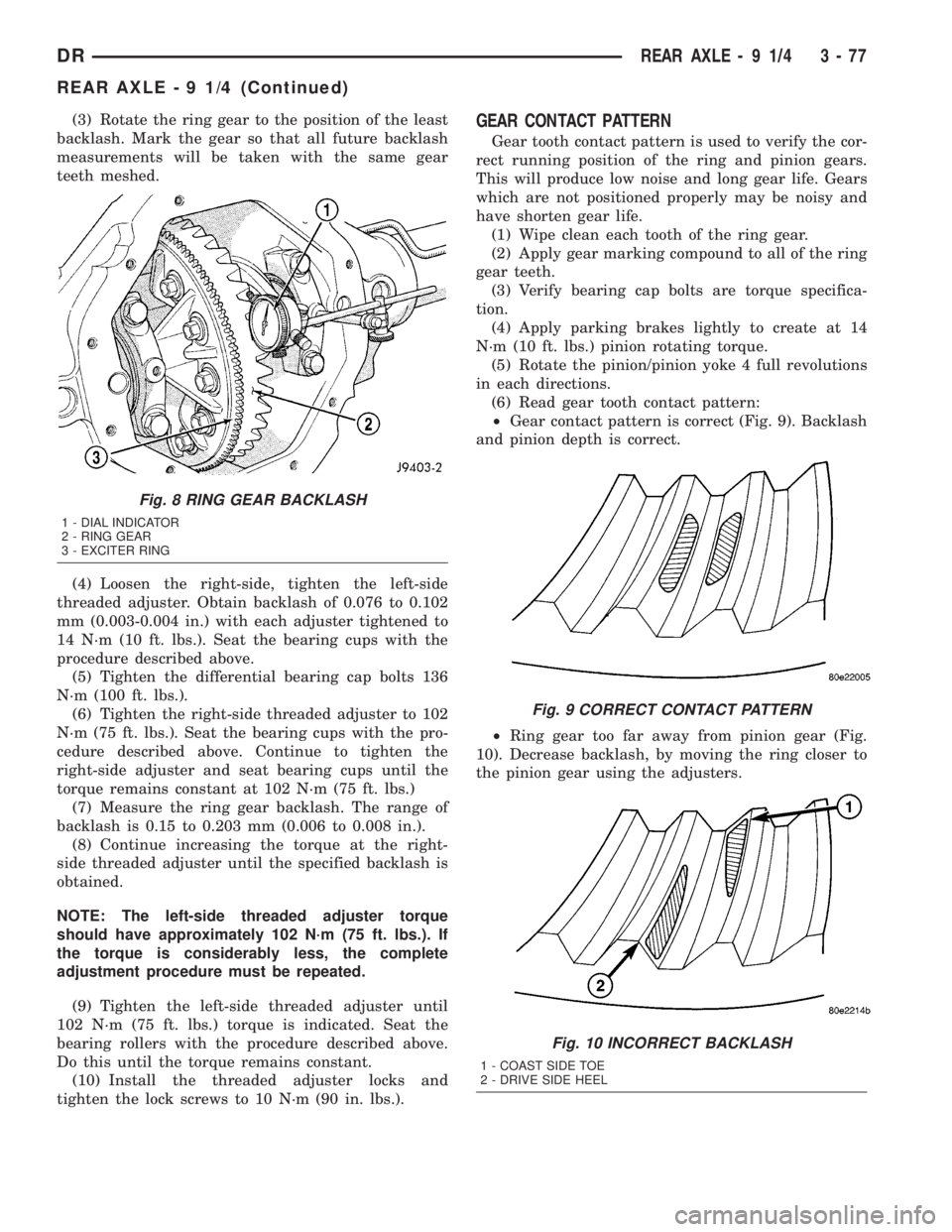
Gear tooth contact pattern is used to verify the cor-
rect running position of the ring and pinion gears.
This will produce low noise and long gear life. Gears
which are not positioned properly may be noisy and
have shorten gear life.
(1) Wipe clean each tooth of the ring gear.
(2) Apply gear marking compound to all of the ring
gear teeth.
(3) Verify bearing cap bolts are torque specifica-
tion.
(4) Apply parking brakes lightly to create at 14
N´m (10 ft. lbs.) pinion rotating torque.
(5) Rotate the pinion/pinion yoke 4 full revolutions
in each directions.
(6) Read gear tooth contact pattern:
²Gear contact pattern is correct (Fig. 9). Backlash
and pinion depth is correct.
²Ring gear too far away from pinion gear (Fig.
10). Decrease backlash, by moving the ring closer to
the pinion gear using the adjusters.
Fig. 8 RING GEAR BACKLASH
1 - DIAL INDICATOR
2 - RING GEAR
3 - EXCITER RING
Fig. 9 CORRECT CONTACT PATTERN
Fig. 10 INCORRECT BACKLASH
1 - COAST SIDE TOE
2 - DRIVE SIDE HEEL
DRREAR AXLE - 9 1/4 3 - 77
REAR AXLE - 9 1/4 (Continued)
Page 176 of 2895
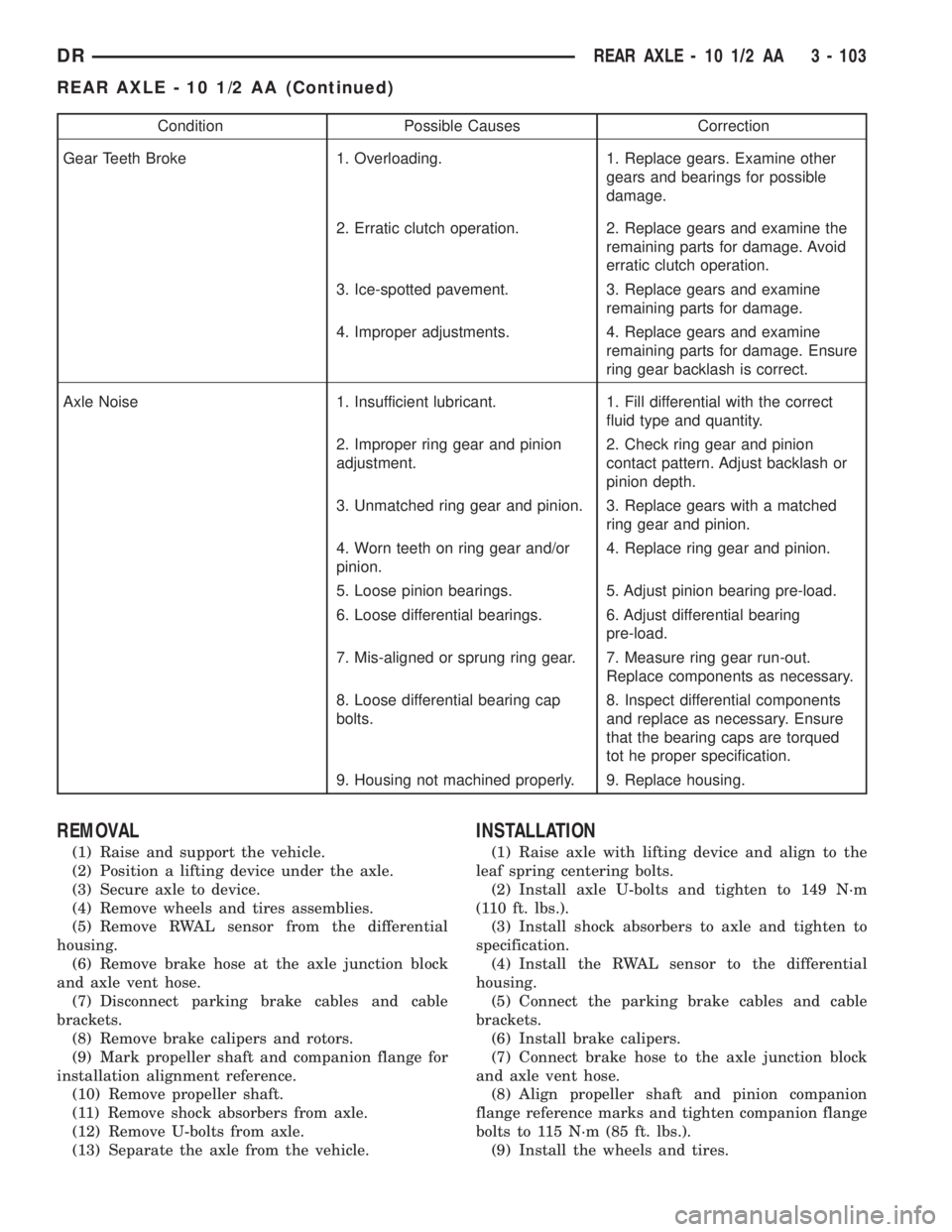
Condition Possible Causes Correction
Gear Teeth Broke 1. Overloading. 1. Replace gears. Examine other
gears and bearings for possible
damage.
2. Erratic clutch operation. 2. Replace gears and examine the
remaining parts for damage. Avoid
erratic clutch operation.
3. Ice-spotted pavement. 3. Replace gears and examine
remaining parts for damage.
4. Improper adjustments. 4. Replace gears and examine
remaining parts for damage. Ensure
ring gear backlash is correct.
Axle Noise 1. Insufficient lubricant. 1. Fill differential with the correct
fluid type and quantity.
2. Improper ring gear and pinion
adjustment.2. Check ring gear and pinion
contact pattern. Adjust backlash or
pinion depth.
3. Unmatched ring gear and pinion. 3. Replace gears with a matched
ring gear and pinion.
4. Worn teeth on ring gear and/or
pinion.4. Replace ring gear and pinion.
5. Loose pinion bearings. 5. Adjust pinion bearing pre-load.
6. Loose differential bearings. 6. Adjust differential bearing
pre-load.
7. Mis-aligned or sprung ring gear. 7. Measure ring gear run-out.
Replace components as necessary.
8. Loose differential bearing cap
bolts.8. Inspect differential components
and replace as necessary. Ensure
that the bearing caps are torqued
tot he proper specification.
9. Housing not machined properly. 9. Replace housing.
REMOVAL
(1) Raise and support the vehicle.
(2) Position a lifting device under the axle.
(3) Secure axle to device.
(4) Remove wheels and tires assemblies.
(5) Remove RWAL sensor from the differential
housing.
(6) Remove brake hose at the axle junction block
and axle vent hose.
(7) Disconnect parking brake cables and cable
brackets.
(8) Remove brake calipers and rotors.
(9) Mark propeller shaft and companion flange for
installation alignment reference.
(10) Remove propeller shaft.
(11) Remove shock absorbers from axle.
(12) Remove U-bolts from axle.
(13) Separate the axle from the vehicle.
INSTALLATION
(1) Raise axle with lifting device and align to the
leaf spring centering bolts.
(2) Install axle U-bolts and tighten to 149 N´m
(110 ft. lbs.).
(3) Install shock absorbers to axle and tighten to
specification.
(4) Install the RWAL sensor to the differential
housing.
(5) Connect the parking brake cables and cable
brackets.
(6) Install brake calipers.
(7) Connect brake hose to the axle junction block
and axle vent hose.
(8) Align propeller shaft and pinion companion
flange reference marks and tighten companion flange
bolts to 115 N´m (85 ft. lbs.).
(9) Install the wheels and tires.
DRREAR AXLE - 10 1/2 AA 3 - 103
REAR AXLE - 10 1/2 AA (Continued)
Page 179 of 2895
(12) Tighten bearing cap bolts to 115 N´m (85 ft.
lbs.).
(13) Tighten adjuster lock bolts to 33 N´m (24 ft.
lbs.).
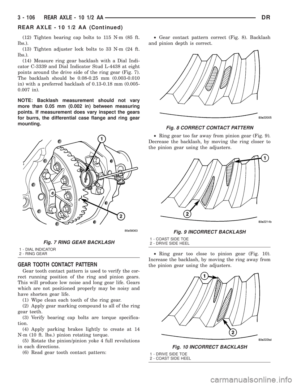
(14) Measure ring gear backlash with a Dial Indi-
cator C-3339 and Dial Indicator Stud L-4438 at eight
points around the drive side of the ring gear (Fig. 7).
The backlash should be 0.08-0.25 mm (0.003-0.010
in) with a preferred backlash of 0.13-0.18 mm (0.005-
0.007 in).
NOTE: Backlash measurement should not vary
more than 0.05 mm (0.002 in) between measuring
points. If measurement does vary inspect the gears
for burrs, the differential case flange and ring gear
mounting.
GEAR TOOTH CONTACT PATTERN
Gear tooth contact pattern is used to verify the cor-
rect running position of the ring and pinion gears.
This will produce low noise and long gear life. Gears
which are not positioned properly may be noisy and
have shorten gear life.
(1) Wipe clean each tooth of the ring gear.
(2) Apply gear marking compound to all of the ring
gear teeth.
(3) Verify bearing cap bolts are torque specifica-
tion.
(4) Apply parking brakes lightly to create at 14
N´m (10 ft. lbs.) pinion rotating torque.
(5) Rotate the pinion/pinion yoke 4 full revolutions
in each directions.
(6) Read gear tooth contact pattern:²Gear contact pattern correct (Fig. 8). Backlash
and pinion depth is correct.
²Ring gear too far away from pinion gear (Fig. 9).
Decrease the backlash, by moving the ring closer to
the pinion gear using the adjusters.
²Ring gear too close to pinion gear (Fig. 10).
Increase the backlash, by moving the ring away from
the pinion gear using the adjusters.
Fig. 7 RING GEAR BACKLASH
1 - DIAL INDICATOR
2 - RING GEAR
Fig. 8 CORRECT CONTACT PATTERN
Fig. 9 INCORRECT BACKLASH
1 - COAST SIDE TOE
2 - DRIVE SIDE HEEL
Fig. 10 INCORRECT BACKLASH
1 - DRIVE SIDE TOE
2 - COAST SIDE HEEL
3 - 106 REAR AXLE - 10 1/2 AADR
REAR AXLE - 10 1/2 AA (Continued)
Page 203 of 2895
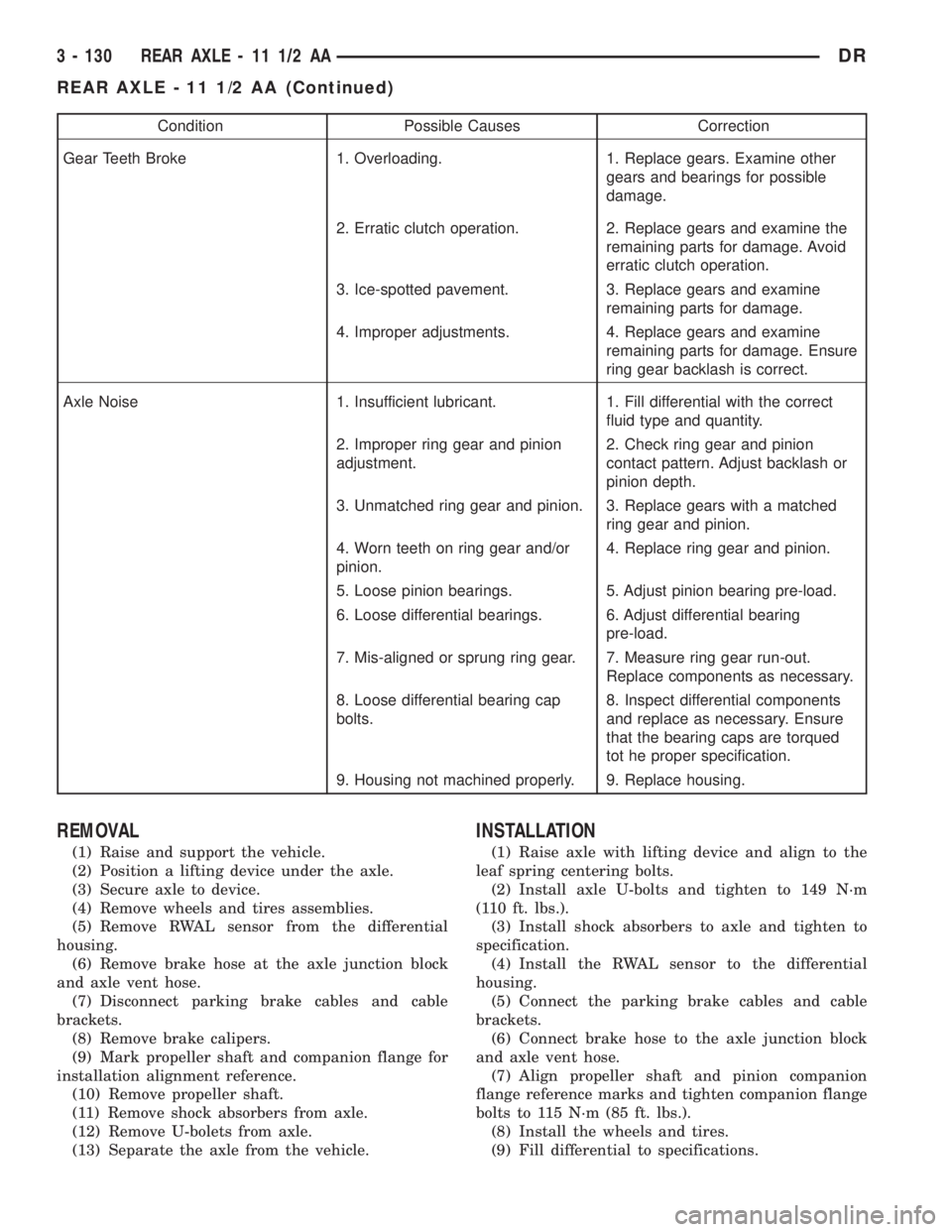
Condition Possible Causes Correction
Gear Teeth Broke 1. Overloading. 1. Replace gears. Examine other
gears and bearings for possible
damage.
2. Erratic clutch operation. 2. Replace gears and examine the
remaining parts for damage. Avoid
erratic clutch operation.
3. Ice-spotted pavement. 3. Replace gears and examine
remaining parts for damage.
4. Improper adjustments. 4. Replace gears and examine
remaining parts for damage. Ensure
ring gear backlash is correct.
Axle Noise 1. Insufficient lubricant. 1. Fill differential with the correct
fluid type and quantity.
2. Improper ring gear and pinion
adjustment.2. Check ring gear and pinion
contact pattern. Adjust backlash or
pinion depth.
3. Unmatched ring gear and pinion. 3. Replace gears with a matched
ring gear and pinion.
4. Worn teeth on ring gear and/or
pinion.4. Replace ring gear and pinion.
5. Loose pinion bearings. 5. Adjust pinion bearing pre-load.
6. Loose differential bearings. 6. Adjust differential bearing
pre-load.
7. Mis-aligned or sprung ring gear. 7. Measure ring gear run-out.
Replace components as necessary.
8. Loose differential bearing cap
bolts.8. Inspect differential components
and replace as necessary. Ensure
that the bearing caps are torqued
tot he proper specification.
9. Housing not machined properly. 9. Replace housing.
REMOVAL
(1) Raise and support the vehicle.
(2) Position a lifting device under the axle.
(3) Secure axle to device.
(4) Remove wheels and tires assemblies.
(5) Remove RWAL sensor from the differential
housing.
(6) Remove brake hose at the axle junction block
and axle vent hose.
(7) Disconnect parking brake cables and cable
brackets.
(8) Remove brake calipers.
(9) Mark propeller shaft and companion flange for
installation alignment reference.
(10) Remove propeller shaft.
(11) Remove shock absorbers from axle.
(12) Remove U-bolets from axle.
(13) Separate the axle from the vehicle.
INSTALLATION
(1) Raise axle with lifting device and align to the
leaf spring centering bolts.
(2) Install axle U-bolts and tighten to 149 N´m
(110 ft. lbs.).
(3) Install shock absorbers to axle and tighten to
specification.
(4) Install the RWAL sensor to the differential
housing.
(5) Connect the parking brake cables and cable
brackets.
(6) Connect brake hose to the axle junction block
and axle vent hose.
(7) Align propeller shaft and pinion companion
flange reference marks and tighten companion flange
bolts to 115 N´m (85 ft. lbs.).
(8) Install the wheels and tires.
(9) Fill differential to specifications.
3 - 130 REAR AXLE - 11 1/2 AADR
REAR AXLE - 11 1/2 AA (Continued)
Page 206 of 2895
(12) Tighten bearing cap bolts to 115 N´m (85 ft.
lbs.).
(13) Tighten adjuster lock bolts to 33 N´m (24 ft.
lbs.).
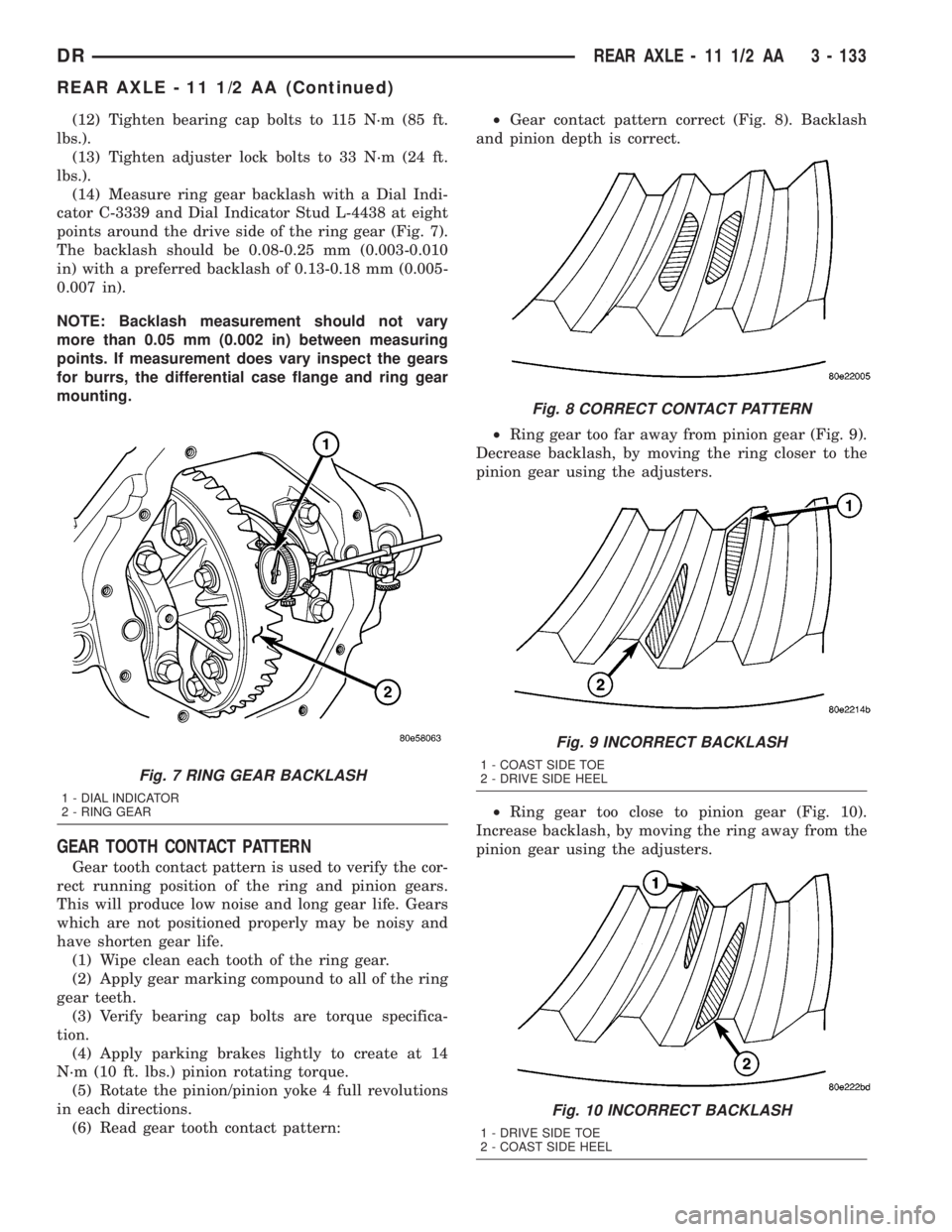
(14) Measure ring gear backlash with a Dial Indi-
cator C-3339 and Dial Indicator Stud L-4438 at eight
points around the drive side of the ring gear (Fig. 7).
The backlash should be 0.08-0.25 mm (0.003-0.010
in) with a preferred backlash of 0.13-0.18 mm (0.005-
0.007 in).
NOTE: Backlash measurement should not vary
more than 0.05 mm (0.002 in) between measuring
points. If measurement does vary inspect the gears
for burrs, the differential case flange and ring gear
mounting.
GEAR TOOTH CONTACT PATTERN
Gear tooth contact pattern is used to verify the cor-
rect running position of the ring and pinion gears.
This will produce low noise and long gear life. Gears
which are not positioned properly may be noisy and
have shorten gear life.
(1) Wipe clean each tooth of the ring gear.
(2) Apply gear marking compound to all of the ring
gear teeth.
(3) Verify bearing cap bolts are torque specifica-
tion.
(4) Apply parking brakes lightly to create at 14
N´m (10 ft. lbs.) pinion rotating torque.
(5) Rotate the pinion/pinion yoke 4 full revolutions
in each directions.
(6) Read gear tooth contact pattern:²Gear contact pattern correct (Fig. 8). Backlash
and pinion depth is correct.
²Ring gear too far away from pinion gear (Fig. 9).
Decrease backlash, by moving the ring closer to the
pinion gear using the adjusters.
²Ring gear too close to pinion gear (Fig. 10).
Increase backlash, by moving the ring away from the
pinion gear using the adjusters.
Fig. 7 RING GEAR BACKLASH
1 - DIAL INDICATOR
2 - RING GEAR
Fig. 8 CORRECT CONTACT PATTERN
Fig. 9 INCORRECT BACKLASH
1 - COAST SIDE TOE
2 - DRIVE SIDE HEEL
Fig. 10 INCORRECT BACKLASH
1 - DRIVE SIDE TOE
2 - COAST SIDE HEEL
DRREAR AXLE - 11 1/2 AA 3 - 133
REAR AXLE - 11 1/2 AA (Continued)
Page 229 of 2895
DIAGNOSIS AND TESTING - MASTER
CYLINDER/POWER BOOSTER...........20
STANDARD PROCEDURE - MASTER
CYLINDER BLEEDING..................20
REMOVAL
REMOVAL - ALL EXCEPT HYDROBOOST . . . 21
REMOVAL - HYDROBOOST.............21
INSTALLATION
INSTALLATION - ALL EXCEPT
HYDROBOOST.......................22
INSTALLATION - HYDROBOOST..........22
PEDAL
DESCRIPTION.........................22
OPERATION...........................22
REMOVAL.............................23
INSTALLATION.........................23
ADJUSTABLE PEDAL MOTOR
DESCRIPTION.........................24
REMOVAL.............................24
INSTALLATION.........................24
POWER BRAKE BOOSTER
DESCRIPTION.........................25
OPERATION...........................25
REMOVAL.............................25
INSTALLATION.........................25
HYDRO-BOOST BRAKE BOOSTER
DIAGNOSIS AND TESTING - HYDRAULIC
BOOSTER...........................25
STANDARD PROCEDURE - BLEEDING......27
REMOVAL.............................27
INSTALLATION.........................27
ROTORS
REMOVAL
REMOVAL - REAR.....................28
REMOVAL - FRONT....................28
INSTALLATION
INSTALLATION - REAR.................28
INSTALLATION - FRONT................29SUPPORT PLATE
REMOVAL.............................29
INSTALLATION.........................29
PARKING BRAKE
DESCRIPTION.........................30
OPERATION...........................30
CABLES
REMOVAL
REMOVAL - FRONT PARKING BRAKE
CABLE..............................31
REMOVAL - REAR PARK BRAKE CABLE . . . 31
REMOVAL - RIGHT REAR CABLE.........31
REMOVAL - LEFT REAR CABLE..........32
INSTALLATION
INSTALLATION - FRONT PARKING BRAKE
CABLE..............................32
INSTALLATION - REAR PARK BRAKE
CABLE..............................32
INSTALLATION - RIGHT REAR CABLE.....32
INSTALLATION - LEFT REAR CABLE......33
SHOES
REMOVAL.............................33
CLEANING - REAR DRUM IN HAT BRAKE....33
INSPECTION - REAR DRUM IN HAT BRAKE . . 33
INSTALLATION.........................34
ADJUSTMENTS
ADJUSTMENT - PARKING BRAKE SHOES . . 34
ADJUSTMENT - WITH ADJUSTING TOOL . . . 36
PEDAL
REMOVAL.............................36
INSTALLATION.........................36
CABLE TENSIONER
ADJUSTMENTS
ADJUSTMENT........................37
RELEASE HANDLE
REMOVAL.............................38
INSTALLATION.........................38
BRAKES - BASE
DIAGNOSIS AND TESTING - BASE BRAKE
SYSTEM
Base brake components consist of the brake shoes,
calipers, wheel cylinders, brake drums, rotors, brake
lines, master cylinder, booster, and parking brake
components.
Brake diagnosis involves determining if the prob-
lem is related to a mechanical, hydraulic, or vacuum
operated component.
The first diagnosis step is the preliminary check.
PRELIMINARY BRAKE CHECK
(1) Check condition of tires and wheels. Damaged
wheels and worn, damaged, or underinflated tires
can cause pull, shudder, vibration, and a condition
similar to grab.(2) If complaint was based on noise when braking,
check suspension components. Jounce front and rear
of vehicle and listen for noise that might be caused
by loose, worn or damaged suspension or steering
components.
(3) Inspect brake fluid level and condition. Note
that the brake reservoir fluid level will decrease in
proportion to normal lining wear.Also note that
brake fluid tends to darken over time. This is
normal and should not be mistaken for contam-
ination.
(a) If fluid level is abnormally low, look for evi-
dence of leaks at calipers, wheel cylinders, brake
lines, and master cylinder.
(b) If fluid appears contaminated, drain out a
sample to examine. System will have to be flushed
if fluid is separated into layers, or contains a sub-
stance other than brake fluid. The system seals
5 - 2 BRAKES - BASEDR
Page 230 of 2895
and cups will also have to be replaced after flush-
ing. Use clean brake fluid to flush the system.
(4) Check parking brake operation. Verify free
movement and full release of cables and pedal. Also
note if vehicle was being operated with parking
brake partially applied.
(5) Check brake pedal operation. Verify that pedal
does not bind and has adequate free play. If pedal
lacks free play, check pedal and power booster for
being loose or for bind condition. Do not road test
until condition is corrected.
(6) Check booster vacuum check valve and hose.
(7) If components checked appear OK, road test
the vehicle.
ROAD TESTING
(1) If complaint involved low brake pedal, pump
pedal and note if it comes back up to normal height.
(2) Check brake pedal response with transmission
in Neutral and engine running. Pedal should remain
firm under constant foot pressure.
(3) During road test, make normal and firm brake
stops in 25-40 mph range. Note faulty brake opera-
tion such as low pedal, hard pedal, fade, pedal pulsa-
tion, pull, grab, drag, noise, etc.
(4) Attempt to stop the vehicle with the parking
brake only and note grab, drag, noise, etc.
PEDAL FALLS AWAY
A brake pedal that falls away under steady foot
pressure is generally the result of a system leak. The
leak point could be at a brake line, fitting, hose, or
caliper/wheel cylinder. If leakage is severe, fluid will
be evident at or around the leaking component.
Internal leakage (seal by-pass) in the master cylin-
der caused by worn or damaged piston cups, may
also be the problem cause.
An internal leak in the ABS or RWAL system may
also be the problem with no physical evidence.
LOW PEDAL
If a low pedal is experienced, pump the pedal sev-
eral times. If the pedal comes back up worn linings,
rotors, drums, or rear brakes out of adjustment are
the most likely causes. The proper course of action is
to inspect and replace all worn component and make
the proper adjustments.
SPONGY PEDAL
A spongy pedal is most often caused by air in the
system. However, thin brake drums or substandard
brake lines and hoses can also cause a spongy pedal.
The proper course of action is to bleed the system,
and replace thin drums and substandard quality
brake hoses if suspected.HARD PEDAL OR HIGH PEDAL EFFORT
A hard pedal or high pedal effort may be due to
lining that is water soaked, contaminated, glazed, or
badly worn. The power booster or check valve could
also be faulty.
PEDAL PULSATION
Pedal pulsation is caused by components that are
loose, or beyond tolerance limits.
The primary cause of pulsation are disc brake
rotors with excessive lateral runout or thickness vari-
ation, or out of round brake drums. Other causes are
loose wheel bearings or calipers and worn, damaged
tires.
NOTE: Some pedal pulsation may be felt during
ABS activation.
BRAKE DRAG
Brake drag occurs when the lining is in constant
contact with the rotor or drum. Drag can occur at one
wheel, all wheels, fronts only, or rears only.
Drag is a product of incomplete brake shoe release.
Drag can be minor or severe enough to overheat the
linings, rotors and drums.
Minor drag will usually cause slight surface char-
ring of the lining. It can also generate hard spots in
rotors and drums from the overheat-cool down pro-
cess. In most cases, the rotors, drums, wheels and
tires are quite warm to the touch after the vehicle is
stopped.
Severe drag can char the brake lining all the way
through. It can also distort and score rotors and
drums to the point of replacement. The wheels, tires
and brake components will be extremely hot. In
severe cases, the lining may generate smoke as it
chars from overheating.
Common causes of brake drag are:
²Seized or improperly adjusted parking brake
cables.
²Loose/worn wheel bearing.
²Seized caliper or wheel cylinder piston.
²Caliper binding on corroded bushings or rusted
slide surfaces.
²Loose caliper mounting.
²Drum brake shoes binding on worn/damaged
support plates.
²Mis-assembled components.
²Long booster output rod.
If brake drag occurs at all wheels, the problem
may be related to a blocked master cylinder return
port, or faulty power booster (binds-does not release).
BRAKE FADE
Brake fade is usually a product of overheating
caused by brake drag. However, brake overheating
DRBRAKES - BASE 5 - 3
BRAKES - BASE (Continued)