ECO mode DODGE RAM 2500 DIESEL 2004 3.G Service Manual
[x] Cancel search | Manufacturer: DODGE, Model Year: 2004, Model line: RAM 2500 DIESEL, Model: DODGE RAM 2500 DIESEL 2004 3.GPages: 426, PDF Size: 7.22 MB
Page 224 of 426
avoid overspeeding the engine and clutch. For accelera-
tion at speeds less than 15 mph (25 km/h), 2nd gear is
recommended.
CAUTION!
When descending a hill, be very careful to downshift
one gear at a time to prevent overspeeding the
engine which can cause valve damage.
Manual Transmission Ð 6-Speed (NV-5600) Ð If
Equipped
NOTE:The parking brake should be engaged before
leaving the vehicle, especially on an incline.
Truck models with manual transmission are equipped
with a clutch interlocking ignition system. The clutch
pedal must be fully depressed to start the vehicle.Fully depress the clutch pedal before shifting gears. As
you release the clutch pedal, lightly depress the accelera-
tor pedal. When launching a stationary vehicle, keep the
engine speed low until the clutch is fully engaged.
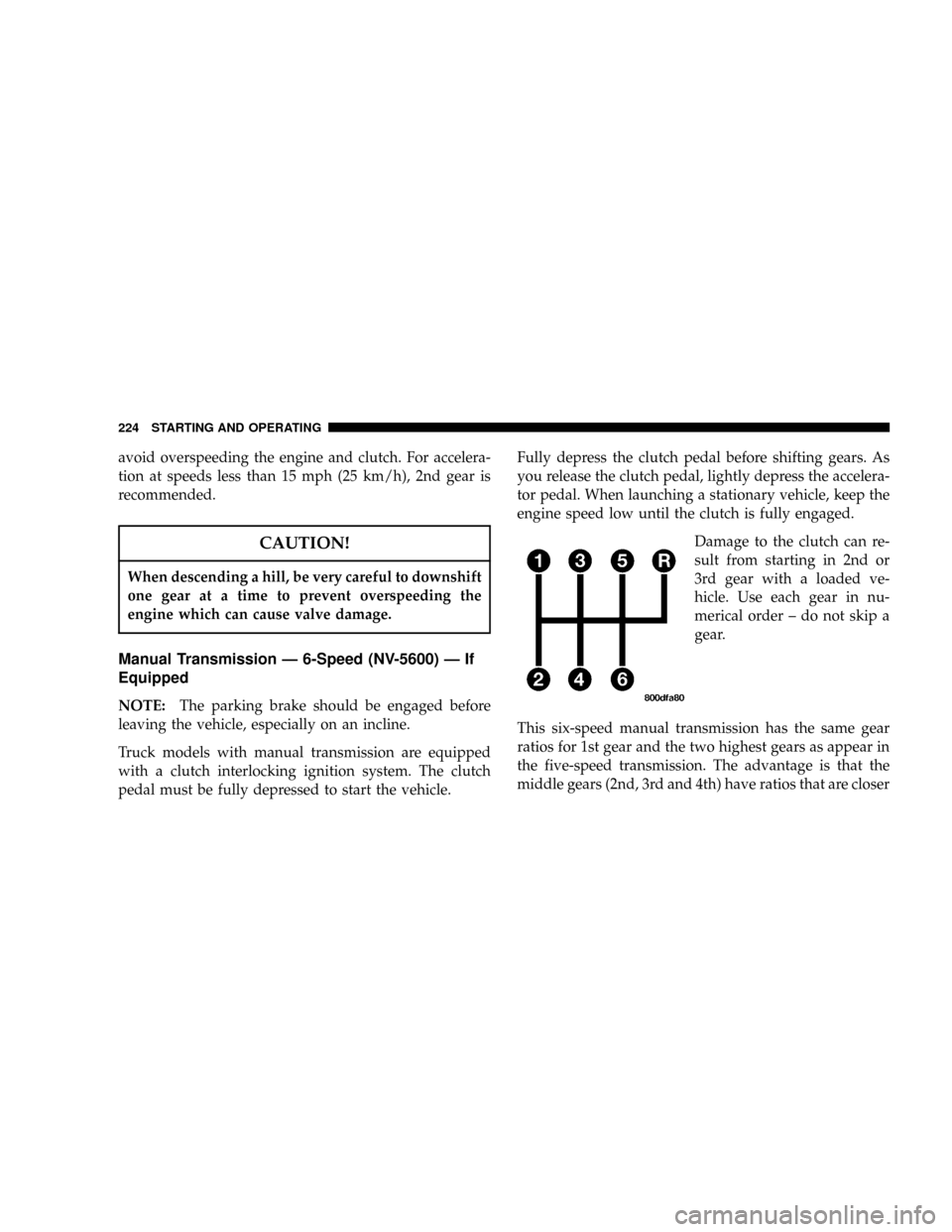
Damage to the clutch can re-
sult from starting in 2nd or
3rd gear with a loaded ve-
hicle. Use each gear in nu-
merical order ± do not skip a
gear.
This six-speed manual transmission has the same gear
ratios for 1st gear and the two highest gears as appear in
the five-speed transmission. The advantage is that the
middle gears (2nd, 3rd and 4th) have ratios that are closer
224 STARTING AND OPERATING
Page 274 of 426
must be considered as part of the total load on your
vehicle. Refer to the Certification label located at the
driver's door for the Gross Vehicle Weight Rating.
WARNING!
Improper towing can lead to an injury accident.
Follow these guidelines to make your trailer towing
as safe as possible:
Axle Lubricant and Trailer Towing
2500/3500 Models
²
The Axles on 2500/3500 Modelsare trailer tow ready
andDO NOT REQUIREany special axle lubes or
additives.
Trailer Towing Recommendations
²
All trailer hitches should be professionally installed on
your vehicle.
²Safety chains must always be used between your
vehicle and trailer.
²Donotinterconnect the hydraulic brake system or
vacuum system of your vehicle with that of the trailer.
This could cause inadequate braking and possible
personal injury. An electrically±actuated electric trailer
brake controller is recommended.
²Trailer brakes are recommended for trailers over 1000
lbs (454 kg) and are required for trailers in excess of
2,000 lbs (907 kg)
274 STARTING AND OPERATING
Page 291 of 426
4. Depress the brake pedal.
5. Shift automatic transmission to Neutral (N) or depress
clutch on manual transmission.
6. Using the point of a ballpoint pen or similar object,
depress the recessed transfer case Neutral (N) button for
1 second.
7. After the Neutral (N) indicator light turns off release
the Neutral (N) button.
8. After the Neutral (N) button has been released the
transfer case will shift to the position identified by the
selector switch.
9. Shift automatic transmission into P (Park).
NOTE:Items 1 through 5 are requirements that must be
met prior to depressing the Neutral (N) selection button,
and must continue to be met until 1 second elapses and
the shift has been completed. If any of these requirements(with the exception of 3 - key ON) are not met prior to
depressing the Neutral (N) button or are no longer met
during the 1 second time, then all of the mode position
indicator lights will flash continuously until all require-
ments are met or until the Neutral (N) button is released.
NOTE:The ignition key must be ON for a shift to take
place and for the position indicator lights to be operable.
If the key is not ON, the shift will not take place and no
position indicator lights will be on or flashing.
NOTE:Flashing neutral (N) position indicator light
indicates that shift requirements have not been met.
STARTING AND OPERATING 291
5
Page 298 of 426
4. Repeat the procedure if the engine does not start.
CAUTION!
Do not engage the starter motor for more than 15
seconds at a time. Allow two minutes between the
cranking intervals.
NOTE:The engine may run rough until the air is forced
from all the fuel lines.
JACK LOCATION
All Models
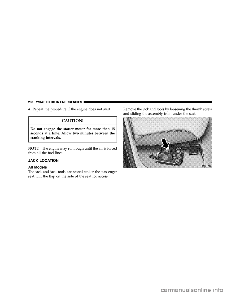
The jack and jack tools are stored under the passenger
seat. Lift the flap on the side of the seat for access.Remove the jack and tools by loosening the thumb screw
and sliding the assembly from under the seat.
298 WHAT TO DO IN EMERGENCIES
Page 351 of 426
Clutch Hydraulic System
The clutch hydraulic system is a sealed maintenance-free
system. In the event of leakage or other malfunction, the
system must be replaced.
Propeller Shaft Universal Joints
Cross Type (No fittings) ÐRelubrication of this type of
universal joint is not required. The seals should be
inspected for external leaks or damage. If external leaks
or damage is evident, the universal joint should be
replaced.
Rear Axle And 4x4 Front Driving Axle Fluid Level
For Model 9.25 Front Axles and 10.5º/11.5º Rear Axles
refer to Recommended Fluids, Lubricants and Genuine
Parts for the correct lubricant type. For normal service,
periodic fluid level checks are not required. When the
vehicle is serviced for other reasons, the exterior surfaces
of the axle assembly should be inspected.When checking the fluid level, the vehicle should be in a
level position. The fluid level should be 1/4º 1/4º (6.4
mm 6.4 mm) below the fill hole on the 9.25º Front Axle.
The fluid level should be 3/4º 1/4º (19 mm 6.4 mm)
below the fill hole on all 10.5º and 1/4º 1/4º (6.4 mm
6.4 mm) on 11.5º Rear Axles.
Drain And Refill
Vehicles operated in normal service do not have regularly
scheduled oil changes. If fluid has become contaminated
with water or subjected to severe service, follow the
recommended change intervals in Maintenance Schedule
ªBº in Section 8 of this manual.
Lubricant Selection
Refer to Recommended Fluids, Lubricants and Genuine
Parts for the correct lubricant type.
NOTE:The presence of water in the gear lubricant will
result in corrosion and possible failure of differential
components. Operation of the vehicle in water, as may be
MAINTAINING YOUR VEHICLE 351
7
Page 366 of 426
FUSE AND RELAY CENTER
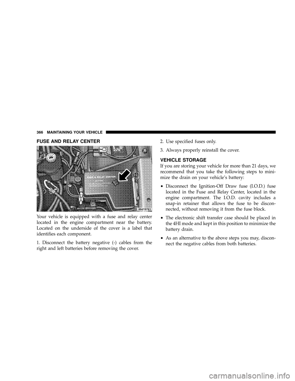
Your vehicle is equipped with a fuse and relay center
located in the engine compartment near the battery.
Located on the underside of the cover is a label that
identifies each component.
1. Disconnect the battery negative (-) cables from the
right and left batteries before removing the cover.2. Use specified fuses only.
3. Always properly reinstall the cover.
VEHICLE STORAGE
If you are storing your vehicle for more than 21 days, we
recommend that you take the following steps to mini-
mize the drain on your vehicle's battery:
²Disconnect the Ignition-Off Draw fuse (I.O.D.) fuse
located in the Fuse and Relay Center, located in the
engine compartment. The I.O.D. cavity includes a
snap-in retainer that allows the fuse to be discon-
nected, without removing it from the fuse block.
²The electronic shift transfer case should be placed in
the 4HI mode and kept in this position to minimize the
battery drain.
²As an alternative to the above steps you may, discon-
nect the negative cables from both batteries.
366 MAINTAINING YOUR VEHICLE
Page 381 of 426
Chassis
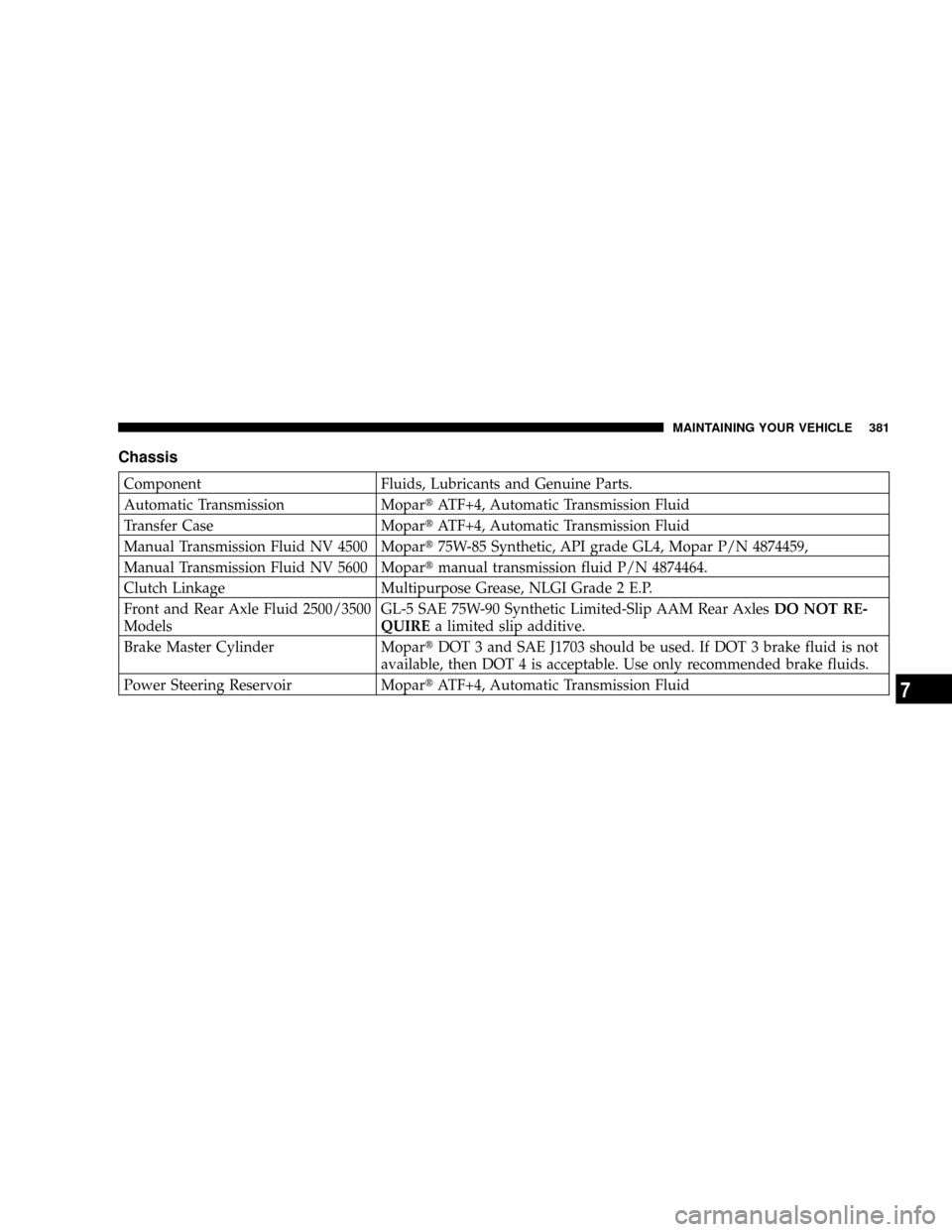
Component Fluids, Lubricants and Genuine Parts.
Automatic Transmission MopartATF+4, Automatic Transmission Fluid
Transfer Case MopartATF+4, Automatic Transmission Fluid
Manual Transmission Fluid NV 4500 Mopart75W-85 Synthetic, API grade GL4, Mopar P/N 4874459,
Manual Transmission Fluid NV 5600 Mopartmanual transmission fluid P/N 4874464.
Clutch Linkage Multipurpose Grease, NLGI Grade 2 E.P.
Front and Rear Axle Fluid 2500/3500
ModelsGL-5 SAE 75W-90 Synthetic Limited-Slip AAM Rear AxlesDO NOT RE-
QUIREa limited slip additive.
Brake Master Cylinder MopartDOT 3 and SAE J1703 should be used. If DOT 3 brake fluid is not
available, then DOT 4 is acceptable. Use only recommended brake fluids.
Power Steering Reservoir MopartATF+4, Automatic Transmission Fluid
MAINTAINING YOUR VEHICLE 381
7