instrument cluster DODGE RAM 2500 DIESEL 2008 3.G User Guide
[x] Cancel search | Manufacturer: DODGE, Model Year: 2008, Model line: RAM 2500 DIESEL, Model: DODGE RAM 2500 DIESEL 2008 3.GPages: 527, PDF Size: 8.88 MB
Page 271 of 527
NOTE:The engine block heater cord is a factory in-
stalled option. If your vehicle is not equipped, heater
cords are available from your authorized Mopartdealer.
²A 12±volt heater built into the fuel filter housing aids
in preventing fuel gelling. It is controlled by a built-in
thermostat.
²A heated intake air system both improves engine
starting and reduces the amount of white smoke
generated by a warming engine.
Manual Transmission ± If Equipped
Apply the parking brake, place the shift lever in NEU-
TRAL and depress the clutch pedal to the floor before
starting the vehicle. This vehicle is equipped with a
clutch interlocking ignition system. It will not start unless
the clutch is fully depressed.
Normal Starting Procedure ± Engine Manifold Air
Temperature Above 66ÉF (19ÉC)
Observe the instrument panel cluster lights when starting
the engine.
1. Always apply the parking brake.
2. Shift into PARK for an automatic transmission. For
vehicles equipped with manual transmissions, fully de-
press and hold the clutch pedal and shift into NEUTRAL.
3. Turn the ignition key to the ON position and watch the
instrument panel cluster lights.
STARTING AND OPERATING 269
5
Page 287 of 527
TRANSMISSION SHIFTING
Automatic Transmission with Overdrive
(68RFE) Ð If Equipped
The gear selector lever display located in the instrument
panel cluster indicates the transmission gear range (the
selector is illuminated for night driving). The selector
lever is mounted on the right side of the steering column.
You must depress the brake pedal to pull the selector
lever out of PARK position (Brake Interlock System). To
drive, move the selector lever from PARK or NEUTRAL
to the desired DRIVE position. Pull the selector lever
toward you when shifting into REVERSE, SECOND,
FIRST or PARK, or when shifting out of PARK.
Gear Ranges
DO NOT race the engine when shifting from PARK or
NEUTRAL position into another gear range.PARK
This gear position supplements the parking brake by
locking the transmission. The engine can be started in
this range. Never use PARK while the vehicle is in
motion. Apply the parking brake when leaving the
vehicle in this range. Always apply parking brake first,
then place the selector in PARK position. On 4-wheel
drive vehicles be sure that the transfer case is in a drive
position!
WARNING!
Never use PARK position on an automatic transmis-
sion as a substitute for the parking brake. Always
apply parking brake fully when parked to guard
against vehicle movement and possible injury or
damage.
STARTING AND OPERATING 285
5
Page 291 of 527
delayed. Shifts into 5th and 6th gear are still allowed
under steady cruise conditions. Closed throttle down-
shifts (for improved engine braking) may occur during
steady braking maneuvers. Pressing the switch a second
time restores normal operation. Normal operation is
always the default at engine start-up.
The TOW HAUL light will illuminate in the instrument
cluster to indicate when the switch has been activated. If
the TOW HAUL modes are desired, the button must be
pressed each time the engine is started.
Electronic Range Select (ERS) Operation
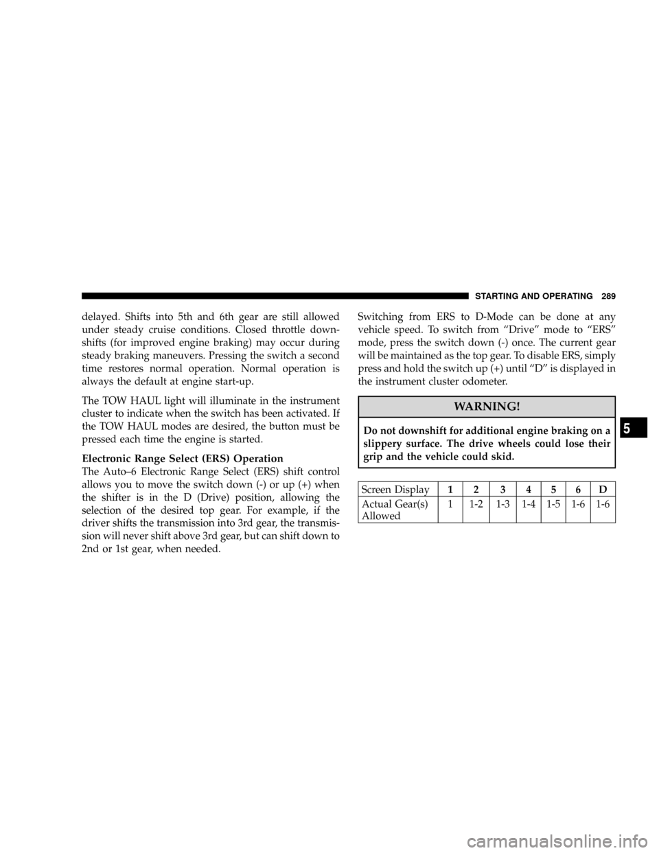
The Auto±6 Electronic Range Select (ERS) shift control
allows you to move the switch down (-) or up (+) when
the shifter is in the D (Drive) position, allowing the
selection of the desired top gear. For example, if the
driver shifts the transmission into 3rd gear, the transmis-
sion will never shift above 3rd gear, but can shift down to
2nd or 1st gear, when needed.Switching from ERS to D-Mode can be done at any
vehicle speed. To switch from ªDriveº mode to ªERSº
mode, press the switch down (-) once. The current gear
will be maintained as the top gear. To disable ERS, simply
press and hold the switch up (+) until ªDº is displayed in
the instrument cluster odometer.
WARNING!
Do not downshift for additional engine braking on a
slippery surface. The drive wheels could lose their
grip and the vehicle could skid.
Screen Display12 3456D
Actual Gear(s)
Allowed1 1-2 1-3 1-4 1-5 1-6 1-6
STARTING AND OPERATING 289
5
Page 297 of 527
This transfer case is intended to be driven in the 2-wheel
drive position (2H) for normal street and highway con-
ditions such as dry hard surfaced roads.
When additional traction is required the transfer case 4H
and 4L positions can be used to lock the front and rear
driveshafts together and force the front and rear wheels
to rotate at the same speed. This is accomplished by
simply moving the shift lever to the desired positions.
The 4H and 4L positions are intended for loose, slippery
road surfaces only. Driving in the 4H and 4L positions on
dry hard surfaced roads may cause increased tire wear
and damage to the driveline components.
The 4-wheel drive light (4WD), located in the instrument
cluster, alerts the driver that the vehicle is in 4-wheel
drive and that the front and rear driveshafts are locked
together. This light illuminates when the transfer case is
shifted to either the 4H or 4L positions. There is no light
for the 2H or NEUTRAL positions.When operating your vehicle in 4L, the engine speed is
approximately three times that of the 2H or 4H positions
at a given road speed. Take care not to overspeed the
engine and do not exceed 25 mph (40 km/h).
Proper operation of 4-wheel drive vehicles depends on
tires of equal size, type and circumference on each wheel.
Any difference will adversely affect shifting and can
cause damage to the transfer case.
NOTE:Do not attempt to make a shift while only the
front or rear wheels are spinning. The transfer case is not
equipped with a synchronizer and therefore the front and
rear driveshaft speeds must be equal for the shift to take
place. Shifting while only the front or rear wheels are
spinning can cause damage to the transfer case.
Because 4-wheel drive provides improved traction, there
is a tendency to exceed safe turning and stopping speeds.
Do not go faster than road conditions permit.
STARTING AND OPERATING 295
5
Page 300 of 527
vehicle in motion, the transfer case will engage/
disengage faster if you momentarily release the accelera-
tor pedal after completing the shift. Apply a constant
force when shifting the transfer case lever.
2H or 4H,4L
With the vehicle rolling at 2 to 3 mph (3 to 5 km/h), shift
an automatic transmission to NEUTRAL or depress the
clutch on a manual transmission. While the vehicle is
coasting at 2 to 3 mph (3 to 5 km/h), shift the transfer
case lever firmly to the desired position. Do not pause in
transfer case NEUTRAL.
NOTE:Pausing in transfer case NEUTRAL in vehicles
equipped with an automatic transmission may require
shutting the engine OFF to avoid gear clash while
completing the shift. If difficulty occurs, shift automatic
transmission to NEUTRAL, hold foot on brake, and turn
engine OFF. Make shift to the desired mode.NOTE:Shifting into or out of 4L is possible with the
vehicle completely stopped, however difficulty may oc-
cur due to the mating clutch teeth not being properly
aligned. Several attempts may be required for clutch
teeth alignment and shift completion to occur. The pre-
ferred method is with the vehicle rolling 2 to 3 mph (3 to
5 km/h). Avoid attempting to engage or disengage 4L
with the vehicle moving faster than 2 to 3 mph (3 to 5
km/h).
NOTE:Do not attempt to shift to or from 4L while the
transmission is in gear or clutch is engaged.
Transfer Case Reminder Light
The four-wheel drive operating light (4WD), located in
the instrument cluster, is used to alert the driver that the
front axle is fully engaged and all four wheels are
driving.
298 STARTING AND OPERATING
Page 302 of 527
in the 4WD LOCK and 4WD LOW positions on dry hard
surfaced roads may cause increased tire wear and dam-
age to the driveline components.
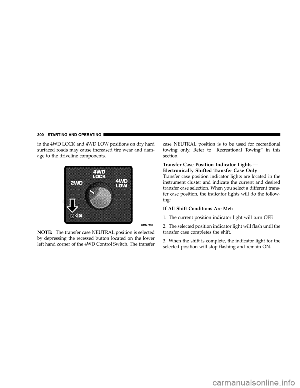
NOTE:The transfer case NEUTRAL position is selected
by depressing the recessed button located on the lower
left hand corner of the 4WD Control Switch. The transfercase NEUTRAL position is to be used for recreational
towing only. Refer to ªRecreational Towingº in this
section.
Transfer Case Position Indicator Lights Ð
Electronically Shifted Transfer Case Only
Transfer case position indicator lights are located in the
instrument cluster and indicate the current and desired
transfer case selection. When you select a different trans-
fer case position, the indicator lights will do the follow-
ing:
If All Shift Conditions Are Met:
1. The current position indicator light will turn OFF.
2. The selected position indicator light will flash until the
transfer case completes the shift.
3. When the shift is complete, the indicator light for the
selected position will stop flashing and remain ON.
300 STARTING AND OPERATING
Page 312 of 527
NOTE:After off-road usage, particularly in sand or
mud, inspect the underside of the vehicle for accumu-
lated dirt at the propeller shaft, axles, U-joints, brake
rotors and calipers.
Use a hose to clean off any accumulation of dirt or mud.
Check the exhaust system and all exposed components
for any sign of damage.
If you experience unusual vibration after driving in mud,
slush or similar conditions, check the wheels for im-
pacted material. Impacted foreign material can cause a
wheel imbalance. Removing the foreign material from
the wheels will correct the situation.PARKING BRAKE
The foot-operated parking brake is positioned below the
lower left corner of the instrument panel. To release the
parking brake, pull the parking brake release handle.
NOTE:The instrument cluster red brake warning light
will come on and flash to indicate that the parking brake
is applied. You must be sure that the parking brake is
fully applied before leaving the vehicle.
310 STARTING AND OPERATING
Page 316 of 527
This Anti-lock Brake System is designed to aid the driver
in maintaining vehicle control under adverse braking
conditions. The system operates with a separate com-
puter to modulate hydraulic pressure to prevent wheel
lockup and help avoid skidding on slippery surfaces.
The system's pump motor runs during an ABS stop to
provide regulated hydraulic pressure. The pump motor
makes a low humming noise during operation. This is
normal.
When you are in a severe braking condition involving
use of the Anti-lock Brake System, you will experience
some pedal drop as the vehicle comes to a complete stop.
This is the result of the system reverting to the base brake
system and is normal.
Engagement of the Anti-lock Brake System may be
accompanied by a pulsing sensation in the brake pedal.
You may also hear a clicking noise. These occurrences are
normal, and indicate that the system is functioning.ABS Warning Light
The Anti-lock Brake System includes an amber warning
light, located in the instrument cluster. When the light is
illuminated, the Anti-lock Brake System is not function-
ing. The system reverts to standard non-anti-lock brakes.
WARNING!
Pumping of the anti-lock brakes will diminish their
effectiveness and may lead to an accident. Pumping
makes the stopping distance longer. Just press firmly
on your brake pedal when you need to slow down or
stop.
314 STARTING AND OPERATING
Page 346 of 527
WARNING!
It is the driver 's responsibility to change to the max
load inflation pressure (cold) low pressure warning
threshold condition when not driving in the light
load condition as defined as two occupants ( 150 lbs
each) plus 200 pounds of cargo. The vehicle ªLight
Load Definitionº is found in the Supplemental Tire
Pressure Information label located on the rear face of
the driver door. Failure to do so may cause you to lose
control resulting in an accident, causing serious or
fatal injury.
To switch back to the max load inflation pressure (cold)
low pressure warning threshold, press the ªLight Loadº
reset switch. It is not necessary to first fill the tires to the
max load inflation pressure (cold) values to switch the
TPMS system to the max load inflation pressure (cold)low pressure warning threshold. If after pressing the
ªLight Loadº reset switch and tire pressures are below
the max load inflation pressure (cold) low pressure
warning thresholds, the TPMS low pressure warning
telltale lamp located in the Instrument Cluster will turn
ON and a chime will sound. The tire pressures are now
required to be inflated to the max load inflation pressure
(cold) values described on the Tire and Loading Informa-
tion label. The Tire and Loading Information label is
located on the drivers side B-pillar. If the ªLight Loadº
reset switch LED turns OFF the TPMS has been reset and
the TPMS is using the max load inflation pressure (cold)
low pressure warning thresholds.
Tire Pressure Monitor System Components
The Tire Pressure Monitor System (TPMS) uses wireless
technology with wheel rim mounted electronic sensors to
monitor tire pressure levels. Sensors, mounted to each
wheel as part of the valve stem, transmit tire pressure
readings to the Receiver Module.
344 STARTING AND OPERATING
Page 347 of 527
NOTE:It is particularly important, for you to check the
tire pressure in all of your tires regularly and to maintain
the proper pressure.
The Tire Pressure Monitoring System (TPMS) consists of
the following components:
²Receiver Module
²4 Wheel Sensors
²2 Trigger Modules (mounted in the front wheel-wells)
²ªLight Loadº Reset Switch (located in the instrument
panel)
²Tire Pressure Monitoring Telltale Lamp
Tire Pressure Monitoring Low Pressure Warnings
The Tire Pressure Monitoring Telltale Lamp will
illuminate in the instrument cluster, and an au-
dible chime will be activated when one or more of
the four active road tire pressures are low. Should this
occur, you should stop as soon as possible, check the
inflation pressure of each tire on your vehicle and inflate
each tire to the vehicle's recommended cold placard
pressure value. The system will automatically update
and the Tire Pressure Monitoring Lamp will extinguish
once the updated tire pressures have been received. The
vehicle may need to be driven for up to 10 minutes above
15 mph (25 km/h) to receive this information.
Check TPMS Warnings
The Tire Pressure Monitoring Telltale Warning Light
located in the Instrument Cluster will flash on and off for
75 seconds and will remain on solid when a system fault
is detected. The system fault will also sound a chime. If
STARTING AND OPERATING 345
5