instrument cluster DODGE RAM 3500 CHASSIS CAB 2009 4.G User Guide
[x] Cancel search | Manufacturer: DODGE, Model Year: 2009, Model line: RAM 3500 CHASSIS CAB, Model: DODGE RAM 3500 CHASSIS CAB 2009 4.GPages: 429, PDF Size: 7.19 MB
Page 226 of 429
AUTOMATIC TRANSMISSION
CAUTION!
Damage to the transmission may occur if the follow-
ing precautions are not observed:
•Shift into PARK only after the vehicle has come to
a complete stop.
•Shift into or out of REVERSE only after the
vehicle has come to a complete stop and the engine
is at idle speed.
•Do not shift from REVERSE, PARK, or NEUTRAL
into any forward gear when the engine is above
idle speed.
•Before shifting into any gear, make sure your foot
is firmly on the brake pedal.
WARNING!
It is dangerous to move the shift lever out of PARK or
NEUTRAL if the engine speed is higher than idle
speed. If your foot is not firmly on the brake pedal,
the vehicle could accelerate quickly forward or in
reverse. You could lose control of the vehicle and hit
someone or something. Only shift into gear when the
engine is idling normally and when your right foot is
firmly on the brake pedal.
Automatic Transmission with Overdrive
The gear shift lever display located in the instrument
panel cluster indicates the transmission gear range (the
selector is illuminated for night driving). The shift lever is
mounted on the right side of the steering column. You
must depress the brake pedal to pull the shift lever out of
PARK position (Brake Interlock System). To drive, move
the shift lever from PARK or NEUTRAL to the desired
224 STARTING AND OPERATING
Page 231 of 429
economy) and automatic closed-throttle downshifts to
3rd gear are performed (for improved braking) when
driving conditions warrant. Pressing the “TOW HAUL
O/D OFF” button a second time to select O/D OFF will
disable 4th and 5th gear completely, which should elimi-
nate any excessive transmission shifting.
The “TOW HAUL” or “O/D OFF” light will illuminate in
the instrument cluster to indicate when the switch has
been activated. Pressing the switch a third time restores
normal operation. If the “TOW HAUL” or “O/D OFF”
modes are desired, the button must be pressed each time
the engine is started.
Torque Converter Clutch
A feature, designed to improve fuel economy, has been
included in the automatic transmission on your vehicle.
A clutch within the torque converter engages automati-
cally at calibrated speeds. This may result in a slightly
different feeling or response during normal operation inthe upper gears. When the vehicle speed drops or during
acceleration when the transmission downshifts to second
gear, the clutch automatically disengages.
NOTE:
•The torque converter clutch will not engage until the
transmission fluid and engine coolant are warm [usu-
ally after 1-3 miles (1.6 - 4.8 km) of driving]. Because
the engine speed is higher when the torque converter
clutch is not engaged, it may seem as if the transmis-
sion is not shifting into Overdrive when cold. This is
normal. Pressing the “TOW HAUL O/D OFF” button,
when the transmission is sufficiently warm, will dem-
onstrate that the transmission is able to shift into and
out of overdrive.
•If the vehicle has not been driven in several days, the
first few seconds of operation after shifting the trans-
mission into gear may seem sluggish. This is due to the
fluid partially draining from the torque converter into
STARTING AND OPERATING 229
5
Page 232 of 429
the transmission. This condition is normal and will not
cause damage to the transmission. The torque con-
verter will refill within five seconds of shifting from
PARK into any other gear position.
FOUR-WHEEL DRIVE OPERATION — IF
EQUIPPED
Four-wheel drive trucks are equipped with either a
manually shifted transfer case or an electronically shifted
transfer case. Refer to the operating instructions for your
transfer case, located in this section.
Manually Shifted Transfer Case Operating
Information/Precautions
The transfer case provides 4 mode positions-2(rear)-
wheel drive high range, 4-wheel drive high range, neu-
tral, and 4-wheel drive low range. This transfer case is intended to be driven in the 2-wheel
drive position (2H) for normal street and highway con-
ditions such as dry, hard surfaced roads.
When additional traction is required, the transfer case 4H
and 4L positions can be used to lock the front and rear
driveshafts together and force the front and rear wheels
to rotate at the same speed. This is accomplished by
simply moving the shift lever to the desired positions.
The 4H and 4L positions are intended for loose, slippery
road surfaces only. Driving in the 4H and 4L positions on
dry, hard surfaced roads may cause increased tire wear
and damage to the driveline components.
The 4-wheel drive light (4WD), located in the instrument
cluster, alerts the driver that the vehicle is in 4-wheel
drive and that the front and rear driveshafts are locked
together. This light illuminates when the transfer case is
shifted to either the 4H or 4L positions. There is no light
for the 2H or NEUTRAL positions.
When operating your vehicle in 4L, the engine speed is
approximately three times that of the 2H or 4H positions
230 STARTING AND OPERATING
Page 236 of 429
•Shifting into or out of 4L is possible with the vehicle
completely stopped, however difficulty may occur due
to the mating clutch teeth not being properly aligned.
Several attempts may be required for clutch teeth
alignment and shift completion to occur. The preferred
method is with the vehicle rolling 2 to 3 mph (3 to
5 km/h). Avoid attempting to engage or disengage 4L
with the vehicle moving faster than 2 to 3 mph (3 to
5 km/h).
•Do not attempt to shift to or from 4L while the
transmission is in gear.
Transfer Case Reminder Light
The 4-wheel drive operating light (4WD), located in the
instrument cluster, is used to alert the driver that the
front axle is fully engaged and all four wheels are
driving.
Electronically Shifted Transfer Case Operating
Information/Precautions (5 Position Switch) — If
Equipped
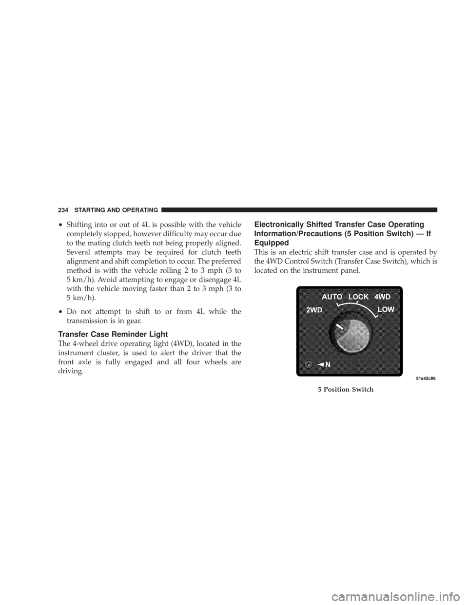
This is an electric shift transfer case and is operated by
the 4WD Control Switch (Transfer Case Switch), which is
located on the instrument panel.
5 Position Switch
234 STARTING AND OPERATING
Page 238 of 429
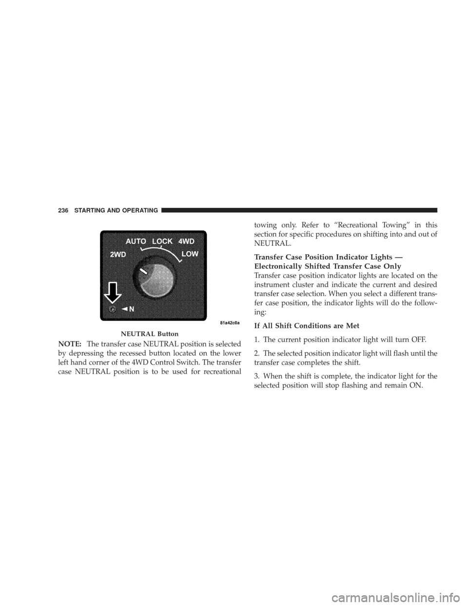
NOTE:The transfer case NEUTRAL position is selected
by depressing the recessed button located on the lower
left hand corner of the 4WD Control Switch. The transfer
case NEUTRAL position is to be used for recreational towing only. Refer to “Recreational Towing” in this
section for specific procedures on shifting into and out of
NEUTRAL.
Transfer Case Position Indicator Lights —
Electronically Shifted Transfer Case Only
Transfer case position indicator lights are located on the
instrument cluster and indicate the current and desired
transfer case selection. When you select a different trans-
fer case position, the indicator lights will do the follow-
ing:
If All Shift Conditions are Met
1. The current position indicator light will turn OFF.
2. The selected position indicator light will flash until the
transfer case completes the shift.
3. When the shift is complete, the indicator light for the
selected position will stop flashing and remain ON.
NEUTRAL Button
236 STARTING AND OPERATING
Page 245 of 429
positions on dry hard surfaced roads may cause in-
creased tire wear and damage to the driveline compo-
nents.
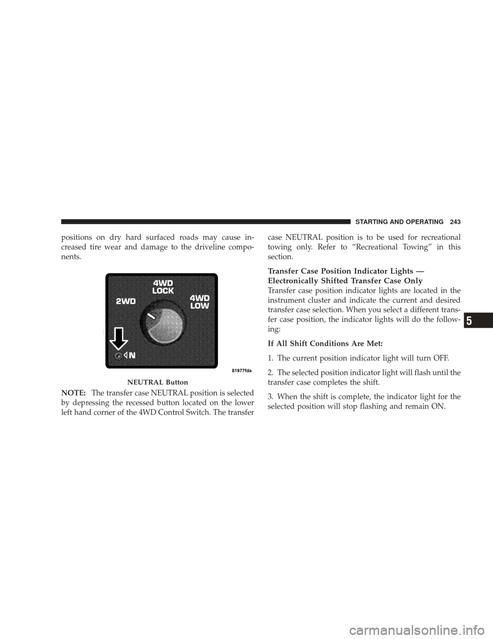
NOTE:The transfer case NEUTRAL position is selected
by depressing the recessed button located on the lower
left hand corner of the 4WD Control Switch. The transfer case NEUTRAL position is to be used for recreational
towing only. Refer to “Recreational Towing” in this
section.
Transfer Case Position Indicator Lights —
Electronically Shifted Transfer Case Only
Transfer case position indicator lights are located in the
instrument cluster and indicate the current and desired
transfer case selection. When you select a different trans-
fer case position, the indicator lights will do the follow-
ing:
If All Shift Conditions Are Met:
1. The current position indicator light will turn OFF.
2. The selected position indicator light will flash until the
transfer case completes the shift.
3. When the shift is complete, the indicator light for the
selected position will stop flashing and remain ON.
NEUTRAL Button
STARTING AND OPERATING 243
5
Page 256 of 429
PARKING BRAKE
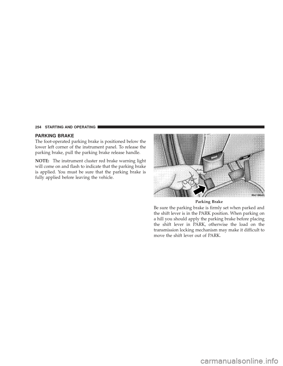
The foot-operated parking brake is positioned below the
lower left corner of the instrument panel. To release the
parking brake, pull the parking brake release handle.
NOTE:The instrument cluster red brake warning light
will come on and flash to indicate that the parking brake
is applied. You must be sure that the parking brake is
fully applied before leaving the vehicle.
Be sure the parking brake is firmly set when parked and
the shift lever is in the PARK position. When parking on
a hill you should apply the parking brake before placing
the shift lever in PARK, otherwise the load on the
transmission locking mechanism may make it difficult to
move the shift lever out of PARK.
Parking Brake
254 STARTING AND OPERATING
Page 259 of 429
The system’s pump motor runs during an ABS stop to
provide regulated hydraulic pressure. The pump motor
makes a low humming noise during operation. This is
normal.
When you are in a severe braking condition involving
use of the ABS, you will experience some pedal drop as
the vehicle comes to a complete stop. This is the result of
the system reverting to the base brake system and is
normal.
Engagement of the ABS may be accompanied by a
pulsing sensation in the brake pedal. You may also hear
a clicking noise. These occurrences are normal, and
indicate that the system is functioning.ABS Warning Light
The ABS includes an amber warning light, located in the
instrument cluster. When the light is illuminated, the ABS
is not functioning. The system reverts to standard non-
anti-lock brakes.
WARNING!
Pumping of the anti-lock brakes will diminish their
effectiveness and may lead to an accident. Pumping
makes the stopping distance longer. Just press firmly
on your brake pedal when you need to slow down or
stop.
STARTING AND OPERATING 257
5
Page 288 of 429
WARNING!
•Never have any smoking materials lit in or near
the vehicle when the gas cap is removed or the
tank filled.
•Never add fuel to the vehicle when the engine is
running. This is in violation of most state and
federal fire regulations and will cause the MIL to
turn on.
NOTE: Tighten the gas cap 1/4 turn until you hear one
click. This is an indication that the cap is properly
tightened.
If the gas cap is not tightened properly, the Malfunction
Indicator Light will come on, Be sure the gas cap is
tightened every time the vehicle is refueled.
WARNING!
A fire may result if gasoline is pumped into a
portable container that is inside of a vehicle. You
could be burned. Always place gas containers on the
ground while filling.
Loose Fuel Filler Cap (Gas Cap) Message
If the vehicle’s diagnostic system determines that the fuel
filler cap in loose, improperly installed or damaged, a
GASCAP message will be displayed in the instrument
cluster. Tighten the gas cap until a “clicking” sound is
heard. This is an indication that the gas cap is properly
tightened. Press the odometer reset button to turn the
message off. If the problem persists, the message will
appear the next time the vehicle is started. This might
indicate a damaged cap. If the problem is detected twice
in a row, the system will turn on the MIL. Resolving the
problem will turn the MIL off.
286 STARTING AND OPERATING
Page 338 of 429
ONBOARD DIAGNOSTIC SYSTEM (OBD II)
Vehicles with 5.7L engines are equipped with a sophisti-
cated onboard diagnostic system called OBD II. This
system monitors the performance of the emissions, en-
gine, and automatic transmission control systems. When
these systems are operating properly, your vehicle will
provide excellent performance and fuel economy, as well
as engine emissions well within current government
regulations.
If any of these systems require service, the OBD II system
will turn on the Malfunction Indicator Light (MIL). It will
also store diagnostic codes and other information to
assist your service technician in making repairs. Al-
though your vehicle will usually be driveable and not
need towing, see your authorized dealer for service as
soon as possible.CAUTION!
Prolonged driving with the MIL on could cause
further damage to the emission control system. It
could also affect fuel economy and driveability. The
vehicle must be serviced before any emissions tests
can be performed.
If the MIL is flashing, severe catalytic converter
damage and power loss will soon occur. Immediate
service is required.
Loose Fuel Filler Cap Message
If the vehicle’s diagnostic system determines that the fuel
filler cap is loose, improperly installed, or damaged, a
gASCAP message will be displayed in the instrument
cluster. Tighten the gas cap until a “clicking” sound is
heard. This is an indication that the gas cap is properly
tightened. Press the odometer reset button to turn the
message off. If the problem persists, the message will
336 MAINTAINING YOUR VEHICLE