brake light DODGE RAM 3500 GAS 2008 3.G Owner's Manual
[x] Cancel search | Manufacturer: DODGE, Model Year: 2008, Model line: RAM 3500 GAS, Model: DODGE RAM 3500 GAS 2008 3.GPages: 554, PDF Size: 9.93 MB
Page 335 of 554
ESP (Electronic Stability Program)
The ESP system enhances directional control and stability
of the vehicle under various driving conditions. ESP
corrects for oversteering or understeering of the vehicle
by applying the brake of the appropriate wheel to assist
in counteracting the oversteer or understeer condition.
Engine power may also be reduced to help the vehicle
maintain the desired path.
ESP uses sensors in the vehicle to determine the vehicle
path intended by the driver and compares it to the actual
path of the vehicle. When the actual path does not match
the intended path, ESP applies the brake of the appropri-
ate wheel to assist in counteracting the oversteer or
understeer condition.
²Oversteer - when the vehicle is turning more than
appropriate for the steering wheel position.
²Understeer - when the vehicle is turning less than
appropriate for the steering wheel position.
ESP/TCS Indicator Light
The ªESP/TCS Indicator Lightº located in the
instrument cluster, starts to flash as soon as the
tires lose traction and the ESP system becomes
active. The ªESP/TCS Indicator Lightº also
flashes when TCS is active. If the ªESP/TCS Indicator
Lightº begins to flash during acceleration, ease up on the
accelerator and apply as little throttle as possible. Be sure
to adapt your speed and driving to the prevailing road
conditions.
STARTING AND OPERATING 333
5
Page 339 of 554
ESP/BAS Warning Lamp and ESP/TCS Indicator
Light
The malfunction indicator for the ESP is combined with
the BAS indicator. The yellow ªESP/BAS Warning
Lampº and the yellow ªESP/TCS Indicator Lightº in the
instrument cluster both come on when the ignition
switch is turned to the ON position. They should both go
out with the engine running. If the ªESP/BAS Warning
Lampº comes on continuously with the engine running,
a malfunction has been detected in either the ESP or BAS
system, or both. If this light remains on after several
ignition cycles, and the vehicle has been driven several
miles/kilometers at speeds greater than 30 mph (48
km/h), see your authorized dealer as soon as possible to
have the problem diagnosed and corrected.
NOTE:
²The ªESP Indicator Lightº and the ªESP/BAS Warning
Lampº come on momentarily each time the ignition
switch is turned ON.
²Each time the ignition is turned ON, the ESP System
will be ON even if it was turned off previously.
²The ESP Control System will make buzzing or clicking
sounds when it is active. This is normal. The sounds
will stop when ESP becomes inactive following the
maneuver that caused the ESP activation.
TSC (Trailer Sway Control)
The TSC system uses sensors in the vehicle to recognize
an excessively swaying trailer and will take the appro-
priate actions to attempt to stop the sway. The system
may reduce engine power and apply the brake of the
appropriate wheel(s) to counteract the sway of the trailer.
TSC will become active automatically once an excessively
swaying trailer is recognized. No driver action is re-
quired. Note that TSC cannot stop all trailers from
swaying. Always use caution when towing a trailer and
follow the trailer tongue weight recommendations. Refer
to ªTrailer Towingº in Section 5 of this manual for more
STARTING AND OPERATING 337
5
Page 340 of 554
information on towing a trailer with your vehicle. When
TSC is functioning, the ªESP/TCS Indicator Lightº will
flash, the engine power may be reduced and you may
feel the brakes being applied to individual wheels to
attempt to stop the trailer from swaying. TSC is disabled
when the ESP system is in the Partial Off or Full Off
modes.
TSC is only active in the default ªESP Onº mode. TSC can
be disabled by pressing the ESP Off button and entering
ªESP Partial Offº mode. It is not active in the ªESP Partial
Offº or ªESP Offº modes. Please refer to the ESP portion
of this section for an explanation of the different ESP
operating modes.WARNING!
If TSC activates while driving, slow the vehicle
down, stop at the nearest safe location, and adjust the
trailer load to eliminate trailer sway.
MULTI-DISPLACEMENT SYSTEM (MDS) Ð 5.7L
ENGINE ONLY
This feature offers improved fuel economy by shutting
off four of the engine's eight cylinders during light load
and cruise conditions. The system is automatic with no
driver inputs or additional driving skills required.
NOTE:The MDS system may take some time to return
to full functionality after a battery disconnect.
338 STARTING AND OPERATING
Page 412 of 554
7. After shift is completed and the NEUTRAL light
comes on, release the NEUTRAL button.
8. Start engine.
9. Shift automatic transmission into REVERSE.
10. Release brake pedal for five seconds and ensure that
there is no vehicle movement.
11. Repeat steps 9 and 10 with the transmission in
DRIVE.
12. Shut engine OFF and place ignition key in the
unlocked OFF position.
13. Shift automatic transmission into PARK or 1st gear
on manual transmissions.
14. Apply parking brake.
15. Attach vehicle to tow vehicle with tow bar.
16. Release parking brake.NOTE:Steps 1 through 5 are requirements that must be
met prior to depressing the NEUTRAL selection button,
and must continue to be met until the four seconds
elapses and the shift has been completed. If any of these
requirements (with the exception of 3 - Key ON) are not
met prior to depressing the NEUTRAL button or are no
longer met during the four second timer, then the NEU-
TRAL indicator light will flash continuously until all
requirements are met or until the NEUTRAL button is
released.
NOTE:The ignition key must be ON for a shift to take
place and for the position indicator lights to be operable.
If the key in not ON, the shift will not take place and no
position indicator lights will be on or flashing.
NOTE:Flashing NEUTRAL position indicator light
indicates that shift requirements have not been met.
410 STARTING AND OPERATING
Page 413 of 554
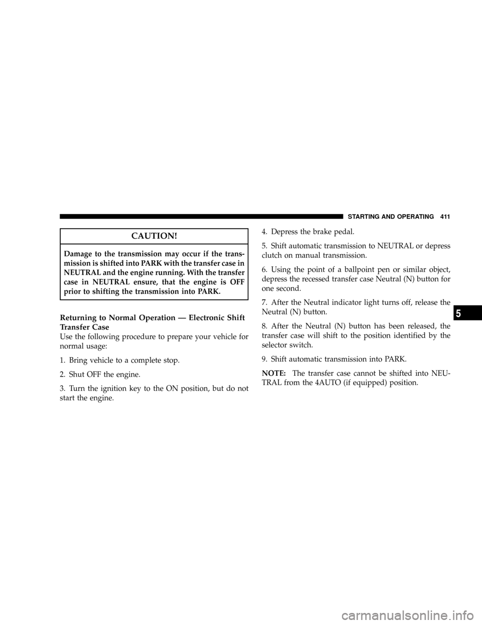
CAUTION!
Damage to the transmission may occur if the trans-
mission is shifted into PARK with the transfer case in
NEUTRAL and the engine running. With the transfer
case in NEUTRAL ensure, that the engine is OFF
prior to shifting the transmission into PARK.
Returning to Normal Operation Ð Electronic Shift
Transfer Case
Use the following procedure to prepare your vehicle for
normal usage:
1. Bring vehicle to a complete stop.
2. Shut OFF the engine.
3. Turn the ignition key to the ON position, but do not
start the engine.4. Depress the brake pedal.
5. Shift automatic transmission to NEUTRAL or depress
clutch on manual transmission.
6. Using the point of a ballpoint pen or similar object,
depress the recessed transfer case Neutral (N) button for
one second.
7. After the Neutral indicator light turns off, release the
Neutral (N) button.
8. After the Neutral (N) button has been released, the
transfer case will shift to the position identified by the
selector switch.
9. Shift automatic transmission into PARK.
NOTE:The transfer case cannot be shifted into NEU-
TRAL from the 4AUTO (if equipped) position.
STARTING AND OPERATING 411
5
Page 414 of 554
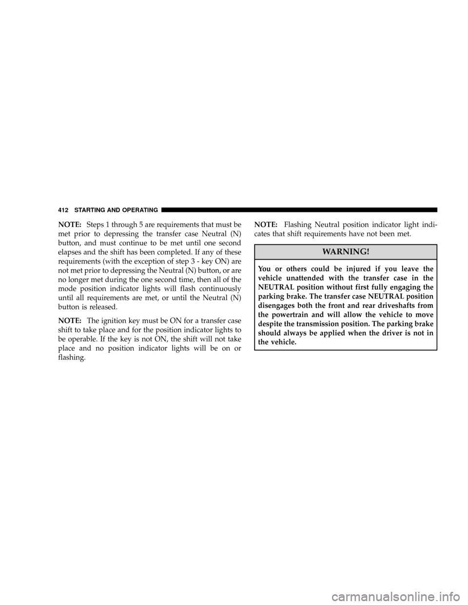
NOTE:Steps 1 through 5 are requirements that must be
met prior to depressing the transfer case Neutral (N)
button, and must continue to be met until one second
elapses and the shift has been completed. If any of these
requirements (with the exception of step 3 - key ON) are
not met prior to depressing the Neutral (N) button, or are
no longer met during the one second time, then all of the
mode position indicator lights will flash continuously
until all requirements are met, or until the Neutral (N)
button is released.
NOTE:The ignition key must be ON for a transfer case
shift to take place and for the position indicator lights to
be operable. If the key is not ON, the shift will not take
place and no position indicator lights will be on or
flashing.NOTE:Flashing Neutral position indicator light indi-
cates that shift requirements have not been met.
WARNING!
You or others could be injured if you leave the
vehicle unattended with the transfer case in the
NEUTRAL position without first fully engaging the
parking brake. The transfer case NEUTRAL position
disengages both the front and rear driveshafts from
the powertrain and will allow the vehicle to move
despite the transmission position. The parking brake
should always be applied when the driver is not in
the vehicle.
412 STARTING AND OPERATING
Page 481 of 554
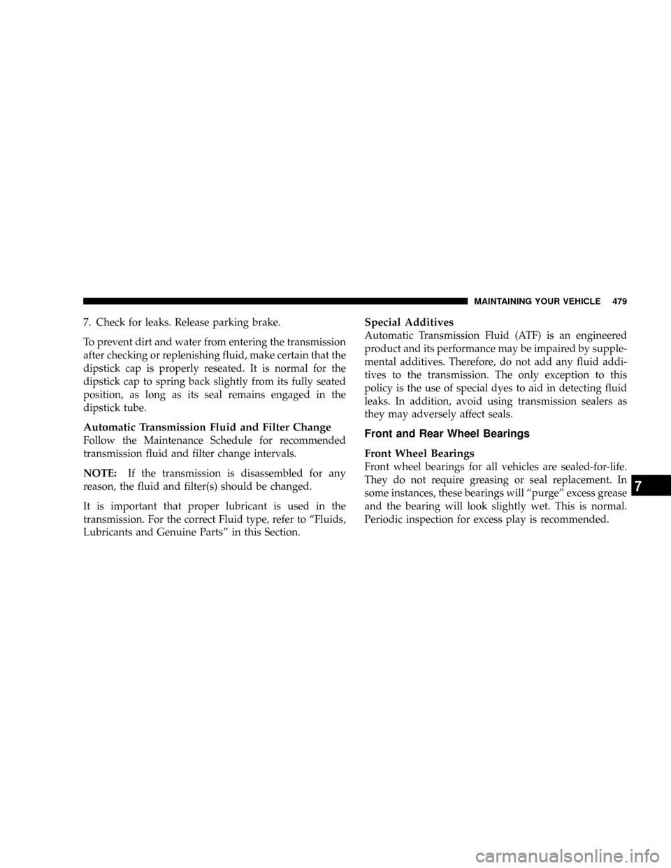
7. Check for leaks. Release parking brake.
To prevent dirt and water from entering the transmission
after checking or replenishing fluid, make certain that the
dipstick cap is properly reseated. It is normal for the
dipstick cap to spring back slightly from its fully seated
position, as long as its seal remains engaged in the
dipstick tube.
Automatic Transmission Fluid and Filter Change
Follow the Maintenance Schedule for recommended
transmission fluid and filter change intervals.
NOTE:If the transmission is disassembled for any
reason, the fluid and filter(s) should be changed.
It is important that proper lubricant is used in the
transmission. For the correct Fluid type, refer to ªFluids,
Lubricants and Genuine Partsº in this Section.
Special Additives
Automatic Transmission Fluid (ATF) is an engineered
product and its performance may be impaired by supple-
mental additives. Therefore, do not add any fluid addi-
tives to the transmission. The only exception to this
policy is the use of special dyes to aid in detecting fluid
leaks. In addition, avoid using transmission sealers as
they may adversely affect seals.
Front and Rear Wheel Bearings
Front Wheel Bearings
Front wheel bearings for all vehicles are sealed-for-life.
They do not require greasing or seal replacement. In
some instances, these bearings will ªpurgeº excess grease
and the bearing will look slightly wet. This is normal.
Periodic inspection for excess play is recommended.
MAINTAINING YOUR VEHICLE 479
7
Page 492 of 554
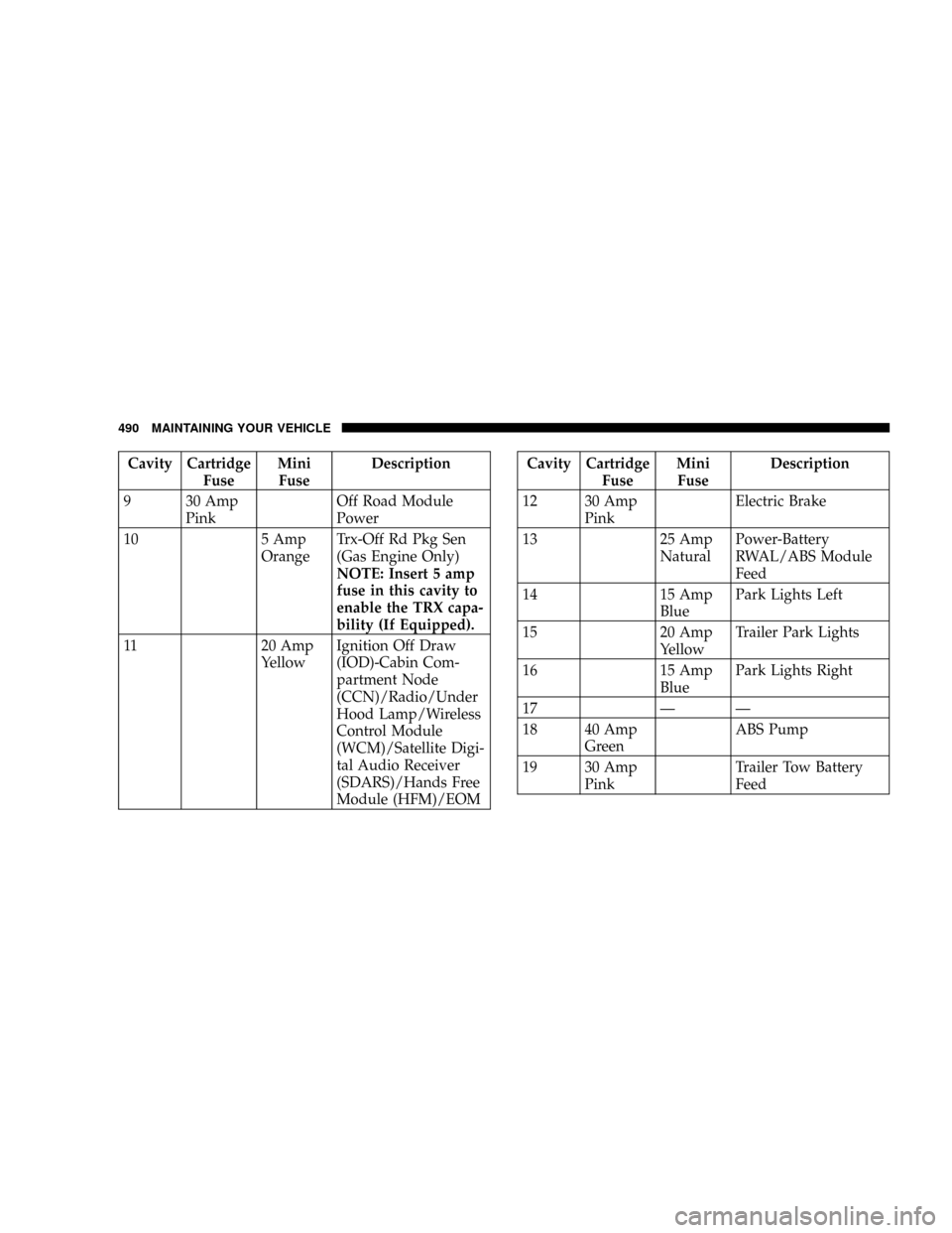
Cavity Cartridge
FuseMini
FuseDescription
9 30 Amp
PinkOff Road Module
Power
10 5 Amp
OrangeTrx-Off Rd Pkg Sen
(Gas Engine Only)
NOTE: Insert 5 amp
fuse in this cavity to
enable the TRX capa-
bility (If Equipped).
11 20 Amp
YellowIgnition Off Draw
(IOD)-Cabin Com-
partment Node
(CCN)/Radio/Under
Hood Lamp/Wireless
Control Module
(WCM)/Satellite Digi-
tal Audio Receiver
(SDARS)/Hands Free
Module (HFM)/EOMCavity Cartridge
FuseMini
FuseDescription
12 30 Amp
PinkElectric Brake
13 25 Amp
NaturalPower-Battery
RWAL/ABS Module
Feed
14 15 Amp
BluePark Lights Left
15 20 Amp
YellowTrailer Park Lights
16 15 Amp
BluePark Lights Right
17 Ð Ð
18 40 Amp
GreenABS Pump
19 30 Amp
PinkTrailer Tow Battery
Feed
490 MAINTAINING YOUR VEHICLE
Page 493 of 554
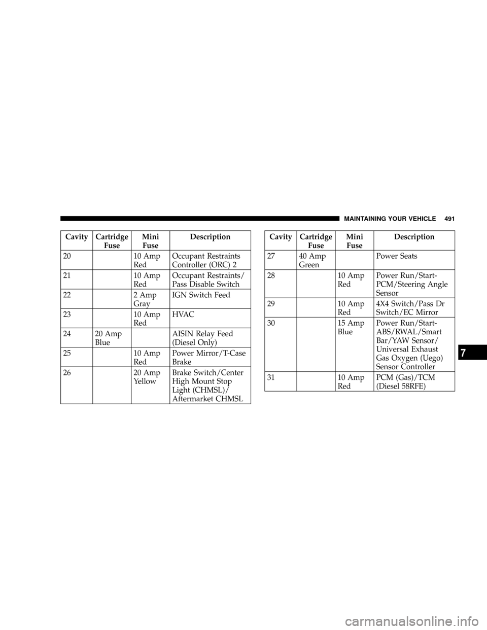
Cavity Cartridge
FuseMini
FuseDescription
20 10 Amp
RedOccupant Restraints
Controller (ORC) 2
21 10 Amp
RedOccupant Restraints/
Pass Disable Switch
22 2 Amp
GrayIGN Switch Feed
23 10 Amp
RedHVAC
24 20 Amp
BlueAISIN Relay Feed
(Diesel Only)
25 10 Amp
RedPower Mirror/T-Case
Brake
26 20 Amp
YellowBrake Switch/Center
High Mount Stop
Light (CHMSL)/
Aftermarket CHMSLCavity Cartridge
FuseMini
FuseDescription
27 40 Amp
GreenPower Seats
28 10 Amp
RedPower Run/Start-
PCM/Steering Angle
Sensor
29 10 Amp
Red4X4 Switch/Pass Dr
Switch/EC Mirror
30 15 Amp
BluePower Run/Start-
ABS/RWAL/Smart
Bar/YAW Sensor/
Universal Exhaust
Gas Oxygen (Uego)
Sensor Controller
31 10 Amp
RedPCM (Gas)/TCM
(Diesel 58RFE)
MAINTAINING YOUR VEHICLE 491
7
Page 517 of 554
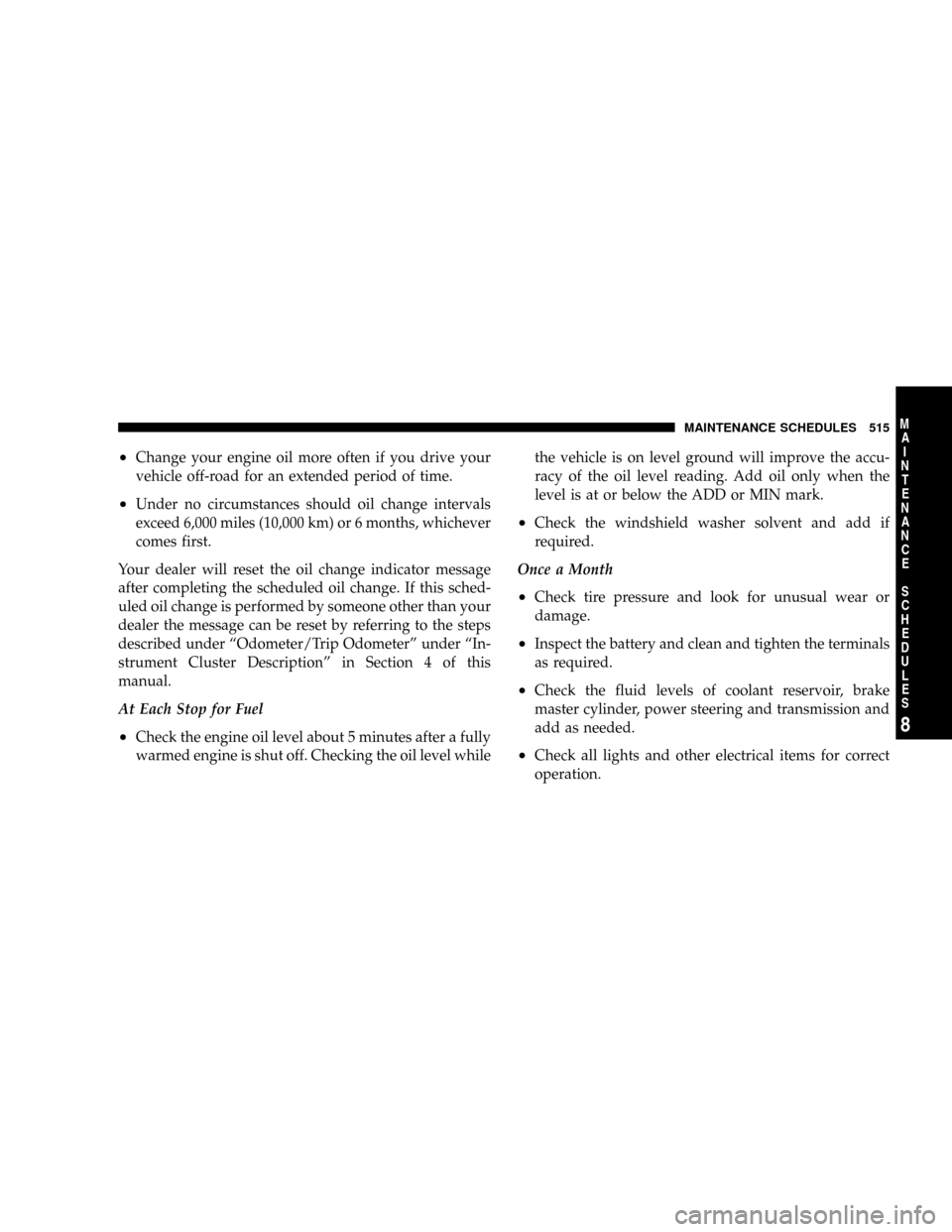
²Change your engine oil more often if you drive your
vehicle off-road for an extended period of time.
²Under no circumstances should oil change intervals
exceed 6,000 miles (10,000 km) or 6 months, whichever
comes first.
Your dealer will reset the oil change indicator message
after completing the scheduled oil change. If this sched-
uled oil change is performed by someone other than your
dealer the message can be reset by referring to the steps
described under ªOdometer/Trip Odometerº under ªIn-
strument Cluster Descriptionº in Section 4 of this
manual.
At Each Stop for Fuel
²Check the engine oil level about 5 minutes after a fully
warmed engine is shut off. Checking the oil level whilethe vehicle is on level ground will improve the accu-
racy of the oil level reading. Add oil only when the
level is at or below the ADD or MIN mark.
²Check the windshield washer solvent and add if
required.
Once a Month
²Check tire pressure and look for unusual wear or
damage.
²Inspect the battery and clean and tighten the terminals
as required.
²Check the fluid levels of coolant reservoir, brake
master cylinder, power steering and transmission and
add as needed.
²Check all lights and other electrical items for correct
operation.
MAINTENANCE SCHEDULES 515
8
M
A
I
N
T
E
N
A
N
C
E
S
C
H
E
D
U
L
E
S