engine overheat DODGE RAM SRT-10 2006 Service User Guide
[x] Cancel search | Manufacturer: DODGE, Model Year: 2006, Model line: RAM SRT-10, Model: DODGE RAM SRT-10 2006Pages: 5267, PDF Size: 68.7 MB
Page 2143 of 5267
CONVERTER-CATALYTIC
DESCRIPTION
WARNING: THE NORMAL OPERATING TEMPERATURE OF THE EXHAUST SYSTEM IS VERY HIGH. THERE-
FORE, NEVER WORK AROUND OR ATTEMPT TO SERVICE ANY PART OF THE EXHAUST SYSTEMUNTIL IT
IS COOLED. SPECIAL CARE SHOULD BE TAKEN WHEN WORKING NEAR THE CATALYTIC CONVERTER.
THE TEMPERATURE OF THE CONVERTER RISES TO A HIGH LEVEL AFTER A SHORT PERIOD OFENGINE
OPERATION TIME.
CAUTION: DO NOT remove spark plug wires from plugs or by any other means short out cylinders. Failure
of the catalytic converter can occur due to a temperature increase caused by unburned fuel passing
through the converter.
The stainless steel catalytic converter body is designed to last the life of the vehicle. Excessive heat can result in
bulging or other distortion, but excessive heat will not be the fault of theconverter. If unburned fuel enters the con-
verter, overheating may occur. If a converter is heat-damaged, correct the cause of the damage at the same time
the converter is replaced. Also, inspect all other components of the exhaust system for heat damage.
Unleaded gasoline must be used to avoid contaminating the catalyst core.
50 State emission vehicles incorporate two mini catalytic converters located after the exhaust manifolds and before
the inline catalytic converter.
OPERATION
The catalytic converter captures and burns any unburned fuel mixture exiting the combustion chambers during the
exhaust stroke of the engine. This process aids in reducing emissions output.
REMOVAL
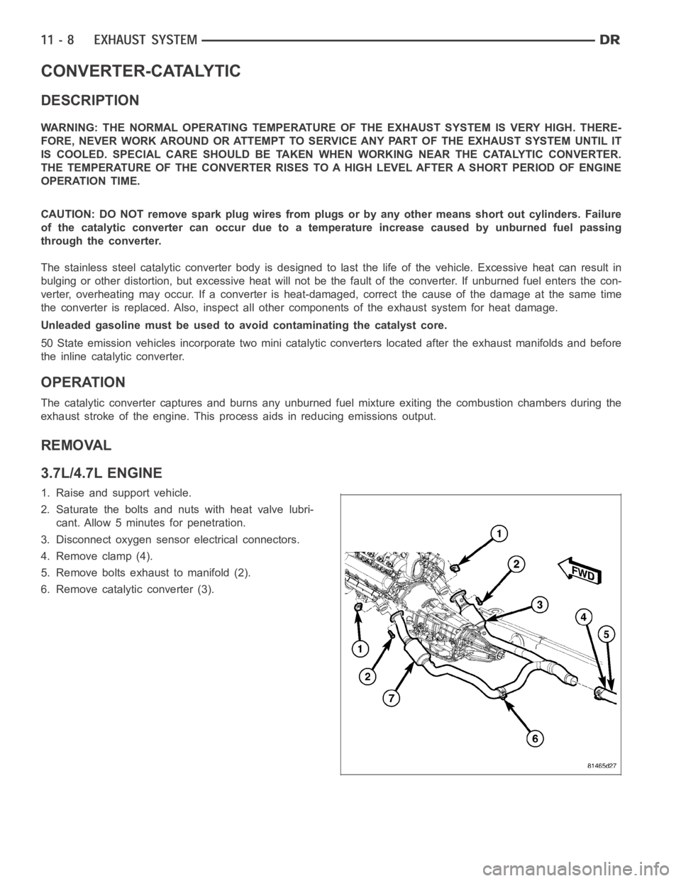
3.7L/4.7L ENGINE
1. Raise and support vehicle.
2. Saturate the bolts and nuts with heat valve lubri-
cant. Allow 5 minutes for penetration.
3. Disconnect oxygen sensor electrical connectors.
4. Remove clamp (4).
5. Remove bolts exhaust to manifold (2).
6. Remove catalytic converter (3).
Page 2145 of 5267
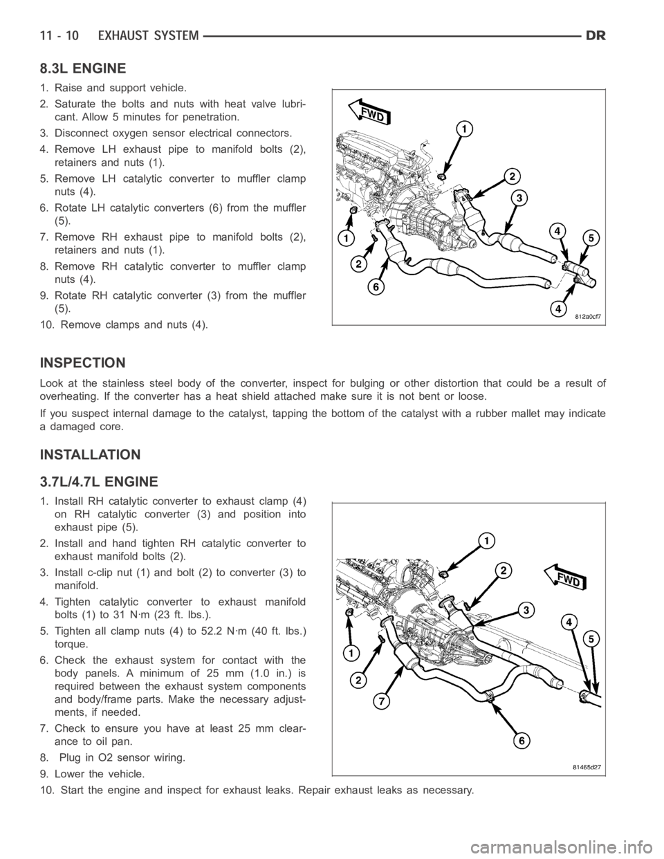
8.3L ENGINE
1. Raise and support vehicle.
2. Saturate the bolts and nuts with heat valve lubri-
cant. Allow 5 minutes for penetration.
3. Disconnect oxygen sensor electrical connectors.
4. Remove LH exhaust pipe to manifold bolts (2),
retainers and nuts (1).
5. Remove LH catalytic converter to muffler clamp
nuts (4).
6. Rotate LH catalytic converters (6) from the muffler
(5).
7. Remove RH exhaust pipe to manifold bolts (2),
retainers and nuts (1).
8. Remove RH catalytic converter to muffler clamp
nuts (4).
9. Rotate RH catalytic converter (3) from the muffler
(5).
10. Remove clamps and nuts (4).
INSPECTION
Look at the stainless steel body of the converter, inspect for bulging or other distortion that could be a result of
overheating. If the converter has a heat shield attached make sure it is notbent or loose.
If you suspect internal damage to the catalyst, tapping the bottom of the catalyst with a rubber mallet may indicate
a damaged core.
INSTALLATION
3.7L/4.7L ENGINE
1. Install RH catalytic converter to exhaust clamp (4)
on RH catalytic converter (3) and position into
exhaust pipe (5).
2. Install and hand tighten RH catalytic converter to
exhaust manifold bolts (2).
3. Install c-clip nut (1) and bolt (2) to converter (3) to
manifold.
4. Tighten catalytic converter to exhaust manifold
bolts(1)to31Nꞏm(23ft.lbs.).
5. Tighten all clamp nuts (4) to 52.2 Nꞏm (40 ft. lbs.)
torque.
6. Check the exhaust system for contact with the
body panels. A minimum of 25 mm (1.0 in.) is
required between the exhaust system components
and body/frame parts. Make the necessary adjust-
ments, if needed.
7. Check to ensure you have at least 25 mm clear-
ance to oil pan.
8. Plug in O2 sensor wiring.
9. Lower the vehicle.
10. Start the engine and inspect for exhaust leaks. Repair exhaust leaks asnecessary.
Page 2163 of 5267
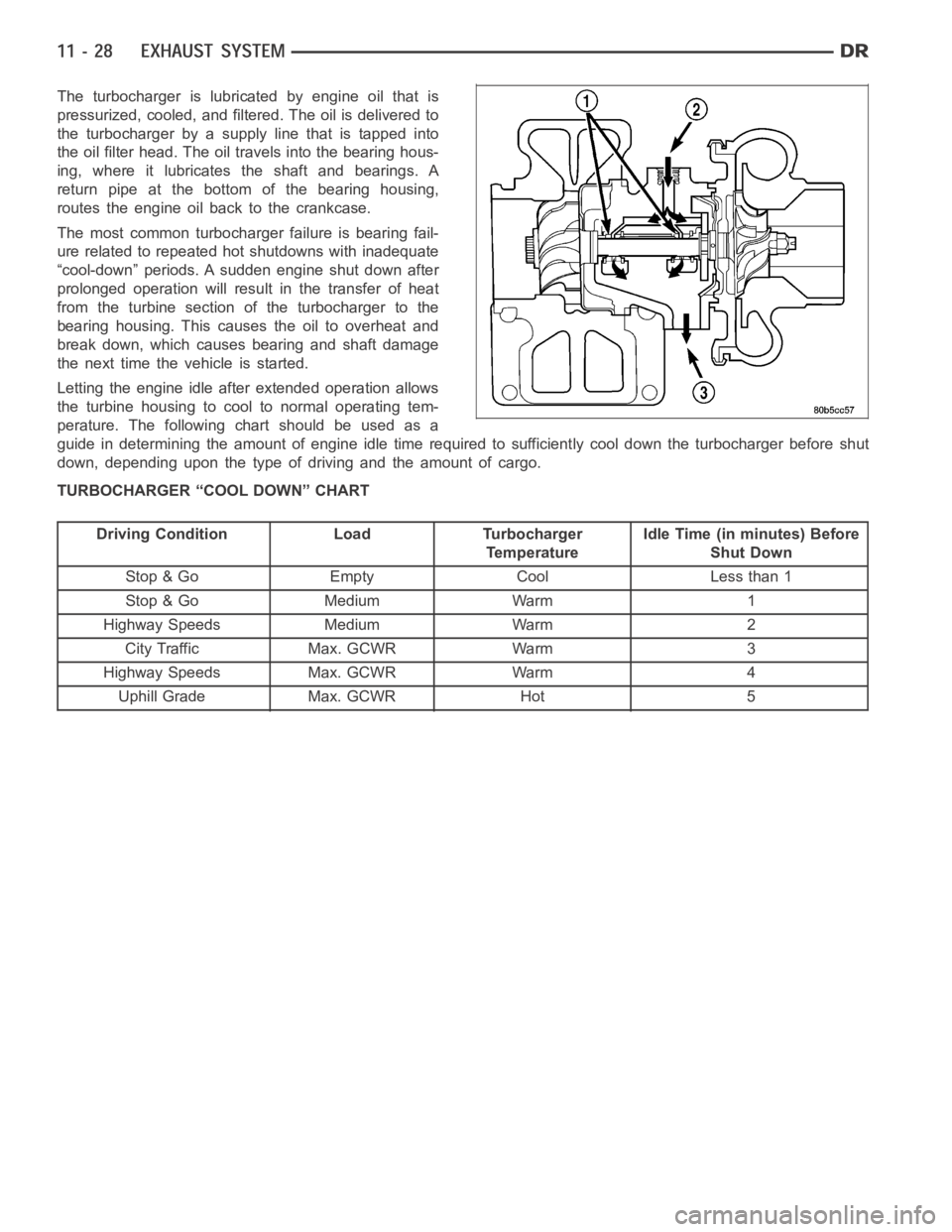
The turbocharger is lubricated by engine oil that is
pressurized, cooled, and filtered. The oil is delivered to
the turbocharger by a supply line that is tapped into
the oil filter head. The oil travels into the bearing hous-
ing, where it lubricates the shaft and bearings. A
return pipe at the bottom of the bearing housing,
routes the engine oil back to the crankcase.
The most common turbocharger failure is bearing fail-
ure related to repeated hot shutdowns with inadequate
“cool-down” periods. A sudden engine shut down after
prolonged operation will result in the transfer of heat
from the turbine section of the turbocharger to the
bearing housing. This causes the oil to overheat and
break down, which causes bearing and shaft damage
thenexttimethevehicleisstarted.
Letting the engine idle after extended operation allows
the turbine housing to cool to normal operating tem-
perature. The following chart should be used as a
guide in determining the amount of engine idle time required to sufficiently cool down the turbocharger before shut
down, depending upon the type of driving and the amount of cargo.
TURBOCHARGER “COOL DOWN” CHART
Driving Condition Load Turbocharger
TemperatureIdle Time (in minutes) Before
Shut Down
Stop & Go Empty Cool Less than 1
Stop & Go Medium Warm 1
Highway Speeds Medium Warm 2
City Traffic Max. GCWR Warm 3
Highway Speeds Max. GCWR Warm 4
Uphill Grade Max. GCWR Hot 5
Page 2724 of 5267

page page
AUTOMATIC TRANSMISSION 42RLE -
ELECTRICAL DIAGNOSTICS
DIAGNOSIS AND TESTING
P0122-TPS/APP CIRCUIT LOW............. 205
P0123-TPS/APP CIRCUIT HIGH............. 207
P0124-TPS/APP INTERMITTENT ............ 209
P0218-HIGH TEMPERATURE OPERATION
A C T I VAT E D................................ 211
P0562-BATTERY VOLTAGE LOW ............ 213
P0602-CONTROL MODULE PROGRAMMING
ERROR/NOT PROGRAMMED............... 217
P0604-INTERNAL CONTROL MODULE RAM . 218
P0605-INTERNAL CONTROL MODULE ROM . 219
P0613-INTERNAL TRANSMISSION
PROCESSOR.............................. 220
P0706-TRANSMISSION RANGE SENSOR
RATIONALITY............................. 221
P0711-TRANSMISSION TEMPERATURE
SENSOR PERFORMANCE.................. 225
P0712-TRANSMISSION TEMPERATURE
SENSOR LOW............................. 228
P0713-TRANSMISSION TEMPERATURE
SENSOR HIGH............................ 231
P0714-TRANSMISSION TEMPERATURE
SENSOR INTERMITTENT................... 235
P0715-INPUT SPEED SENSOR 1 CIRCUIT . . . 238
P0720-OUTPUT SPEED SENSOR CIRCUIT . . 243
P0725-ENGINE SPEED SENSOR CIRCUIT . . . 248
P0731-GEAR RATIO ERROR IN 1ST ......... 250
P0732-GEAR RATIO ERROR IN 2ND ........ 252
P0733-GEAR RATIO ERROR IN 3RD ........ 254
P0734-GEAR RATIO ERROR IN 4TH ........ 256
P0736-GEAR RATIO ERROR IN REVERSE . . . 258
P0740-TCC OUT OF RANGE ................ 260
P0750-LR SOLENOID CIRCUIT............. 262
P0755-2/4 SOLENOID CIRCUIT ............. 266
P0760-OD SOLENOID CIRCUIT ............. 270
P0765-UD SOLENOID CIRCUIT ............. 274
P0841-LR PRESSURE SWITCH
RATIONALITY............................. 279
P0845-2/4 HYDRAULIC PRESSURE TEST . . . 284
P0846-2/4 PRESSURE SWITCH
RATIONALITY............................. 289
P0868-LINE PRESSURE LOW .............. 294
P0869-LINE PRESSURE HIGH .............. 300
P0870-OD HYDRAULIC PRESSURE TEST . . . 306P0871-OD PRESSURE SWITCH
RATIONALITY.............................. 311
P0882-TCM POWER INPUT LOW ........... 316
P0883-TCM POWER INPUT HIGH ........... 320
P0884-POWER UPAT SPEED .............. 324
P0890-SWITCHED BATTERY ............... 325
P0897-TRANSMISSION FLUID
DETERIORATED........................... 329
P0932-LINE PRESSURE SENSOR CIRCUIT . . 330
P0934-LINE PRESSURE SENSOR CIRCUIT
LOW...................................... 333
P0935-LINE PRESSURE SENSOR CIRCUIT
HIGH..................................... 338
P0944-LOSS OF HYDRAULIC PUMP PRIME . 343
P0992-2/4/OD HYDRAULIC PRESSURE
TEST..................................... 345
P128B-TCM POWER CONTROL CIRCUIT 2
LOW - TIPM............................... 346
P128C-TCM POWER CONTROL CIRCUIT 2
HIGH - TIPM............................... 349
P128D-TCM POWER CONTROL CIRCUIT 2
OPEN - TIPM.............................. 352
P128E-TCM POWER CONTROL CIRCUIT 2
OVERCURRENT - TIPM.................... 355
P1684-BATTERY WAS DISCONNECTED . . . . . 359
P1713-RESTRICTED MANUAL VALVE IN T2
RANGE................................... 362
P1745-TRANSMISSION LINE PRESSURE
TOO HIGH FOR TOO LONG................ 363
P1775-SOLENOID SWITCH VALVE
LATCHED IN TCC POSITION................ 364
P1776-SOLENOID SWITCH VALVE
LATCHED IN LR POSITION................. 369
P1790-FAULT IMMEDIATELY AFTER SHIFT . . 374
P1794-SPEED SENSOR GROUND ERROR . . 375
P1797-MANUAL SHIFT OVERHEAT .......... 378
U0100 LOST COMMUNICATION WITH
ECM/PCM................................. 379
U0002 CAN C BUS OFF PERFORMANCE . . . . 381
U0121 LOST COMMUNICATION WITH ABS . . 383
U0141 LOST COMMUNICATION WITH FCM . . 385
STANDARD PROCEDURE
PRE-DIAGNOSTIC TROUBLESHOOTING
PROCEDURE - 42RLE...................... 387
42RLE TRANSMISSION VERIFICATION
TEST - VER 1............................. 388
Page 2732 of 5267
P0218-HIGH TEMPERATURE OPERATION ACTIVATED
For a complete wiring diagramRefer to Section 8W.
When Monitored:
Whenever the engine is running.
Set Condition:
Immediately when a Overheat shift schedule is activated when the Transmission Oil Temperature reaches 155°
C or 240° F.
Possible Causes
ENGINE COOLING SYSTEM OPERATION
TRANSMISSION OIL COOLER PLUGGED
H I G H T E M P E R AT U R E O P E R AT I O N S A C T I VAT E D
Always perform the Pre-Diagnostic Troubleshooting procedure before proceeding. (Refer to 21 - TRANSMIS-
SION/TRANSAXLE/AUTOMATIC - 42RLE - STANDARD PROCEDURE)
Theory of Operation
If the transmission oil temperature rises above 115° C (240° F), the overheat shift schedule is activated refer to
Transmission Operation as a function of Transmission Oil Temperature andthe code is set. The DTC is an infor-
mational code only and is being set to aid the technician in determining root cause of a customer driveability issue.
The code is also intended to alert the technician to determine if a cooling system malfunction has occurred or if an
additional transmission air to oil cooler should be added to the vehicle ifthe customer regularly drives in a manner
that overheats the transmission. Extended operation above 115° C (240° F)will reduce the durability of the trans-
mission and should be avoided. Correcting the cooling system malfunctionor installing an additional transmission oil
cooler will improve transmission durability especially for customers who operate in city/construction stop and go traf-
fic, tow trailers regularly, drive aggressively in low gear or drive regularly in mountainous areas.
Diagnostic Test
1.CHECK ENGINE COOLING SYSTEM
Perform Engine Cooling System diagnostics per the Service Information.
Is the Engine Cooling System functioning properly?
Ye s>>
Go To 2
No>>
Repair the cause of the engine overheating. Refer to the Service Information for the related diagnostic
or repair procedures.
Perform 42RLE TRANSMISSION VERIFICATION TEST - VER 1. (Refer to 21 - TRANSMISSION/
TRANSAXLE/AUTOMATIC - 42RLE - STANDARD PROCEDURE)
2.TRANSMISSION OIL COOLER RESTRICTED
Check the Transmission Oil Cooler Flow in accordance with the Service Information.
Is the transmission oil cooler restricted or plugged?
Ye s>>
Go To 3
No>>
Repair the cause of the plugged Transmission Oil Cooler as necessary and repair or replace the Trans-
mission Oil Cooler per the Service Information.
Perform 42RLE TRANSMISSION VERIFICATION TEST - VER 1. (Refer to 21 - TRANSMISSION/
TRANSAXLE/AUTOMATIC - 42RLE - STANDARD PROCEDURE)
Page 2899 of 5267
P1797-MANUAL SHIFT OVERHEAT
For a complete wiring diagramRefer to Section 8W.
When Monitored:
Continuously with engine running.
Set Condition:
If the Engine Temperature exceeds 123° C (255° F) or the Transmission Temperature exceeds 135° C (275° F)
while in AutoStick
mode. Note: Aggressive driving or driving in low for extended periods of time will set this
DTC.
Possible Causes
MANUAL SHIFT OVERHEAT
Always perform the 42RLE Pre-Diagnostic Troubleshooting procedure before proceeding. (Refer to 21 -
TRANSMISSION/TRANSAXLE/AUTOMATIC - 42RLE - STANDARD PROCEDURE)
Theory of Operation
The major cause of heat build up in the transmission is torque converter slip.WiththetransmissionintheAuto-
Stick
mode, the torque converter can slip during aggressive driving or heavy loading conditions such as trailer
towing or driving up steep grades. In the non AutoStick
mode, internal controller logic prevents the transmission
from overheating by managing the shift and EMCC schedule. In the AutoStick
mode, when the transmission or
engine temperature approaches an overheat condition, the manual shift overheat DTC sets and the AutoStick
mode is temporarily suspended until the temperature returns to normal.
Diagnostic Test
1.MANUAL SHIFT OVERHEAT
This is an informational DTC only.
With the scan tool, check the DTC EVENT DATA to help identify the conditionsin which the DTC was set.
Check the engine and transmission cooling system for proper operation.
Check the Radiator Cooling Fan operation.
Check the Transmission Cooling operation.
Check the Transmission Fluid Level per the Service Information to verify that it is not overfilled.
NOTE: Aggressive driving or driving in low for extended periods of time will set this DTC.
If there are no possible causes remaining, view repair.
Repair
If the Transmission Fluid is low, repair any Transmission Fluid leak as necessary and adjust the Trans-
mission Fluid Level per the Service Information. Refer to Service Information for the related symptoms
and repair as necessary.
Perform 42RLE TRANSMISSION VERIFICATION TEST - VER 1. (Refer to 21 - TRANSMISSION/
TRANSAXLE/AUTOMATIC - 42RLE - STANDARD PROCEDURE)
Page 3014 of 5267
FLUID AND FILTER
DIAGNOSIS AND TESTING
CAUSES OF BURNT FLUID
Burnt, discolored fluid is a result of overheating which has two primary causes.
1. A result of restricted fluid flow through the main and/or auxiliary cooler. This condition is usually the result of a
faulty or improperly installed drainback valve, a damaged oil cooler, or severe restrictions in the coolers and lines
caused by debris or kinked lines.
2. Heavy duty operation with a vehicle not properly equipped for this type of operation. Trailer towing or similar high
load operation will overheat the transmission fluid if the vehicle is improperly equipped. Such vehicles should
have an auxiliary transmission fluid cooler, a heavy duty cooling system,and the engine/axle ratio combination
needed to handle heavy loads.
EFFECTS OF INCORRECT FLUID LEVEL
Alowfluidlevelallowsthepumptotakeinairalongwiththefluid.Airinthe fluid will cause fluid pressures to be
low and develop slower than normal. If the transmission is overfilled, thegears churn the fluid into foam. This aer-
ates the fluid and causing the same conditions occurring with a low level. In either case, air bubbles cause fluid
overheating, oxidation, and varnish buildup which interferes with valveand clutch operation. Foaming also causes
fluid expansion which can result in fluid overflow from the transmission vent or fill tube. Fluid overflow can easily be
mistaken for a leak if inspection is not careful.
FLUID CONTAMINATION
Transmission fluid contamination is generally a result of:
adding incorrect fluid
failure to clean dipstick and fill tube when checking level
engine coolant entering the fluid
internal failure that generates debris
overheat that generates sludge (fluid breakdown)
failure to replace contaminated converter after repair
The use of non-recommended fluids can result in transmission failure. Theusual results are erratic shifts, slippage,
abnormal wear and eventual failure due to fluid breakdown and sludge formation. Avoid this condition by using rec-
ommended fluids only.
The dipstick cap and fill tube should be wiped clean before checking fluid level. Dirt, grease and other foreign mate-
rial on the cap and tube could fall into the tube if not removed beforehand. Take the time to wipe the cap and tube
clean before withdrawing the dipstick.
Engine coolant in the transmission fluid is generally caused by a cooler malfunction. The only remedy is to replace
the radiator as the cooler in the radiator is not a serviceable part. If coolant has circulated through the transmission,
an overhaul is necessary.
The torque converter should also be replaced whenever a failure generatessludge and debris. This is necessary
because normal converter flushing procedures will not remove all contaminants.
STANDARD PROCEDURE
FLUID LEVEL CHECK
The transmission sump has a dipstick to check oil similar to most automatictransmissions. It is located on the left
side of the engine. Be sure to wipe all dirt from dipstick handle before removing.
The torque converter fills in both the PARK and NEUTRAL positions. Place the selector lever in PARK to be sure
that the fluid level check is accurate.The engine should be running at idle speed for at least one minute, with
the vehicle on level ground.At normal operating temperature (approximately 82° C or 180° F), the fluidlevel is
correct if it is in the HOT region (cross-hatched area) on the oil level indicator. The fluid level should be in COLD
region at 21° C (70° F) fluid temperature. Adjust fluid level as necessary.Use only Mopar
ATF+4, Automatic Trans-
mission Fluid.
Page 3077 of 5267
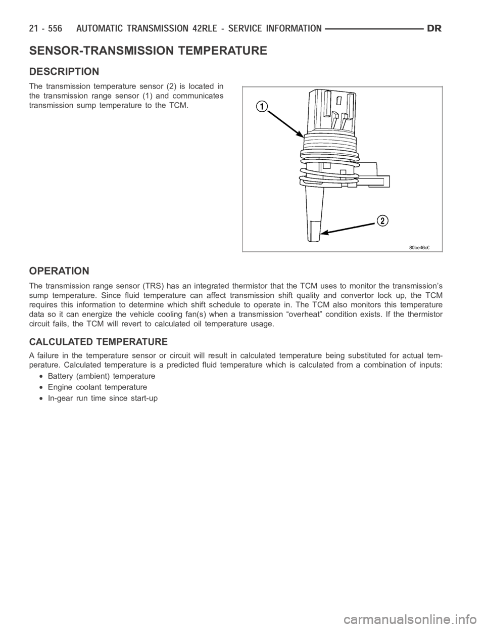
SENSOR-TRANSMISSION TEMPERATURE
DESCRIPTION
The transmission temperature sensor (2) is located in
the transmission range sensor (1) and communicates
transmission sump temperature to the TCM.
OPERATION
The transmission range sensor (TRS) has an integrated thermistor that theTCM uses to monitor the transmission’s
sump temperature. Since fluid temperature can affect transmission shiftquality and convertor lock up, the TCM
requires this information to determine which shift schedule to operate in. The TCM also monitors this temperature
data so it can energize the vehicle cooling fan(s) when a transmission “overheat” condition exists. If the thermistor
circuit fails, the TCM will revert to calculated oil temperature usage.
CALCULATED TEMPERATURE
A failure in the temperature sensor or circuit will result in calculated temperature being substituted for actual tem-
perature. Calculated temperature is a predicted fluid temperature whichis calculated from a combination of inputs:
Battery (ambient) temperature
Engine coolant temperature
In-gear run time since start-up
Page 3109 of 5267
P0218-HIGH TEMPERATURE OPERATION ACTIVATED
For a complete wiring diagramRefer to Section 8W.
Theory of Operation
The DTC is intended as an informational DTC to aid the technician in determining the root cause of a customer
dirveability issue. The DTC is also intended to alert the technician to determine if a cooling system malfunction has
occurred or if an additional transmission air to oil cooler is needed to support the customers driving behavior.
When Monitored:
Whenever the engine is running.
Set Condition:
Immediately after a Overheat shift schedule is activated when the Transmission temperature exceeds 127° C
or 260° F.
Possible Causes
H I G H T E M P E R AT U R E O P E R AT I O N A C T I VAT E D
TORQUE CONVERTER CLUTCH SLIPPING / NOT ACTIVATING
EXCESSIVE TIME IDLING IN GEAR
Always perform the Pre-Diagnostic Troubleshooting procedure before proceeding. (Refer to 21 - TRANSMIS-
SION/TRANSAXLE/AUTOMATIC - 45RFE/545RFE - STANDARD PROCEDURE)
Diagnostic Test
1.HIGH TEMPERATURE OPERATION
This DTC is an informational DTC designed to aid the Technician in diagnosing shift quality complaints.
This DTC indicates that the transmission has been operating in the
Overheatshift schedule which may generate
a customer complaint.
The customer driving patterns may indicate the need for an additional transmission oil cooler.
Verify proper Engine cooling system operation which would affect proper transmission operation.
Verify proper torque converter clutch operation.
With the scan tool, check the DTC EVENT DATA to help identify the conditionsin which the DTC was set.
If there are no possible causes remaining, view repair.
Repair
Repair the cause of transmission overheating. Refer to the Service Information for the proper repair
procedure. Make sure to check for any Service Bulletins pertaining to thisproblem.
Perform 45RFE/545RFE TRANSMISSION VERIFICATION TEST - VER 1. (Refer to 21- TRANSMIS-
SION/TRANSAXLE/AUTOMATIC - 45RFE/545RFE - STANDARD PROCEDURE)
Page 3207 of 5267

9.CHECK THE (F856) 5-VOLT SUPPLY CIRCUIT FOR A SHORT TO GROUND
Measure the resistance between ground and the (F856) 5-volt Supply
circuit.
Is the resistance below 5.0 ohms?
Ye s>>
Repair the (F856) 5-volt Supply circuit for a short to ground.
Perform 45RFE/545RFE TRANSMISSION VERIFICATION
TEST - VER 1.
No>>
Using the schematics as a guide, check the Powertrain
Control Module (PCM) terminals for corrosion, damage, or
terminal push out. Pay particular attention to all power and
ground circuits. If no problems are found, replace the PCM
per the Service Information.With the scan tool, perform
QUICK LEARN.
Perform 45RFE/545RFE TRANSMISSION VERIFICATION
TEST - VER 1. (Refer to 21 - TRANSMISSION/TRANS-
AXLE/AUTOMATIC - 45RFE/545RFE - STANDARD PRO-
CEDURE)
10.COMPARE SCAN TOOL TO PRESSURE GAUGE
Turn the ignition off to the lock position.
Connect the Line Pressure Adapter, Miller tool #8259 and 0-300 psi Test Gauge, Miller tool #C-3293-SP. Refer to
the Service Information for proper installation procedure.
CAUTION: Apply parking brake.
Start the engine.
In the following steps, compare thescan tool Line Pressure to the PressureGauge readings in each gear.
CAUTION: Do not overheat transmission.
With the gear selector in park, raise the RPM to 1500, and compare line pressure readings.
Firmly apply the brakes, move the gear selector into reverse, raise the RPMto 1500, and compare the line pressure
readings.
Firmly apply the brakes, move the gear selector into drive, raise the RPM to1500, and compare the line pressure
readings.
Did the scan tool Line Pressure readings match the Pressure Gauge readings±10psi?
Ye s>>
Go To 11
No>>
Replace the Line Pressure Sensor per the Service Information.
Perform 45RFE/545RFE TRANSMISSION VERIFICATION TEST - VER 1. (Refer to 21- TRANSMIS-
SION/TRANSAXLE/AUTOMATIC - 45RFE/545RFE - STANDARD PROCEDURE)