length DODGE RAM SRT-10 2006 Service User Guide
[x] Cancel search | Manufacturer: DODGE, Model Year: 2006, Model line: RAM SRT-10, Model: DODGE RAM SRT-10 2006Pages: 5267, PDF Size: 68.7 MB
Page 1780 of 5267
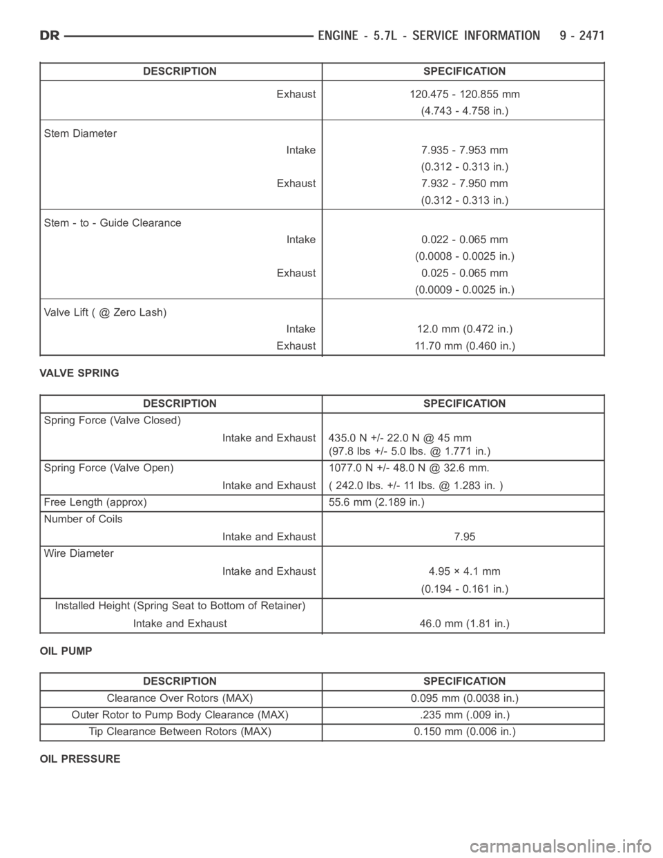
DESCRIPTION SPECIFICATION
Exhaust 120.475 - 120.855 mm
(4.743 - 4.758 in.)
Stem Diameter
Intake 7.935 - 7.953 mm
(0.312 - 0.313 in.)
Exhaust 7.932 - 7.950 mm
(0.312 - 0.313 in.)
Stem - to - Guide Clearance
Intake 0.022 - 0.065 mm
(0.0008 - 0.0025 in.)
Exhaust 0.025 - 0.065 mm
(0.0009 - 0.0025 in.)
ValveLift(@ZeroLash)
Intake 12.0 mm (0.472 in.)
Exhaust 11.70 mm (0.460 in.)
VALVE SPRING
DESCRIPTION SPECIFICATION
Spring Force (Valve Closed)
Intake and Exhaust 435.0 N +/- 22.0 N @ 45 mm
(97.8 lbs +/- 5.0 lbs. @ 1.771 in.)
Spring Force (Valve Open) 1077.0 N +/- 48.0 N @ 32.6 mm.
Intake and Exhaust ( 242.0 lbs. +/- 11 lbs. @ 1.283 in. )
Free Length (approx) 55.6 mm (2.189 in.)
Number of Coils
Intake and Exhaust 7.95
Wire Diameter
Intake and Exhaust 4.95 × 4.1 mm
(0.194 - 0.161 in.)
Installed Height (Spring Seat to Bottom of Retainer)
Intake and Exhaust 46.0 mm (1.81 in.)
OIL PUMP
DESCRIPTION SPECIFICATION
Clearance Over Rotors (MAX) 0.095 mm (0.0038 in.)
Outer Rotor to Pump Body Clearance (MAX) .235 mm (.009 in.)
Tip Clearance Between Rotors (MAX) 0.150 mm (0.006 in.)
OIL PRESSURE
Page 1852 of 5267
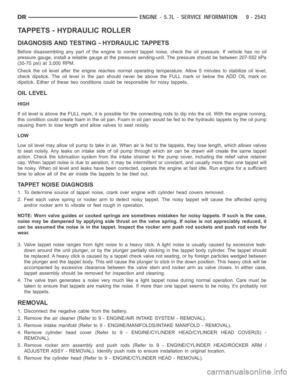
TAPPETS - HYDRAULIC ROLLER
DIAGNOSIS AND TESTING - HYDRAULIC TAPPETS
Before disassembling any part of the engine to correct tappet noise, checkthe oil pressure. If vehicle has no oil
pressure gauge, install a reliable gauge at the pressure sending-unit. The pressure should be between 207-552 kPa
(30-70 psi) at 3,000 RPM.
Check the oil level after the engine reaches normal operating temperature. Allow 5 minutes to stabilize oil level,
check dipstick. The oil level in the pan should never be above the FULL mark or below the ADD OIL mark on
dipstick. Either of these two conditions could be responsible for noisy tappets.
OIL LEVEL
HIGH
If oil level is above the FULL mark, it is possible for the connecting rods todip into the oil. With the engine running,
this condition could create foam in the oil pan. Foam in oil pan would be fed to the hydraulic tappets by the oil pump
causing them to lose length and allow valves to seat noisily.
LOW
Low oil level may allow oil pump to take in air. When air is fed to the tappets,they lose length, which allows valves
to seat noisily. Any leaks on intake side of oil pump through which air can bedrawn will create the same tappet
action. Check the lubrication system from the intake strainer to the pump cover, including the relief valve retainer
cap. When tappet noise is due to aeration, it may be intermittent or constant, and usually more than one tappet will
be noisy. When oil level and leaks have been corrected, operate the engine at fast idle. Run engine for a sufficient
time to allow all of the air inside the tappets to be bled out.
TAPPET NOISE DIAGNOSIS
1. To determine source of tappet noise, crank over engine with cylinder head covers removed.
2. Feel each valve spring or rocker arm to detect noisy tappet. The noisy tappet will cause the affected spring
and/or rocker arm to vibrate or feel rough in operation.
NOTE: Worn valve guides or cocked springs are sometimes mistaken for noisytappets. If such is the case,
noise may be dampened by applying side thrust on the valve spring. If noise is not appreciably reduced, it
can be assumed the noise is in the tappet. Inspect the rocker arm push rod sockets and push rod ends for
wear.
3. Valve tappet noise ranges from light noise to a heavy click. A light noiseis usually caused by excessive leak-
down around the unit plunger, or by the plunger partially sticking in the tappet body cylinder. The tappet should
be replaced. A heavy click is caused by a tappet check valve not seating, or by foreign particles wedged between
the plunger and the tappet body. This will cause the plunger to stick in the down position. This heavy click will be
accompanied by excessive clearance between the valve stem and rocker arm as valve closes. In either case,
tappet assembly should be removed for inspection and cleaning.
4. The valve train generates a noise very much like a light tappet noise during normal operation. Care must be
taken to ensure that tappets are making the noise. If more than one tappet seems to be noisy, it’s probably not
the tappets.
REMOVAL
1. Disconnect the negative cable from the battery.
2. Remove the air cleaner (Refer to 9 - ENGINE/AIR INTAKE SYSTEM - REMOVAL).
3. Remove intake manifold (Refer to 9 - ENGINE/MANIFOLDS/INTAKE MANIFOLD-REMOVAL).
4. Remove cylinder head cover (Refer to 9 - ENGINE/CYLINDER HEAD/CYLINDERHEAD COVER(S) -
REMOVAL).
5. Remove rocker arm assembly and push rods (Refer to 9 - ENGINE/CYLINDER HEAD/ROCKER ARM /
ADJUSTER ASSY - REMOVAL). Identify push rods to ensure installation in original location.
6. Remove the cylinder head (Refer to 9 - ENGINE/CYLINDER HEAD - REMOVAL).
Page 1919 of 5267
INSTALLATION - ENGINE
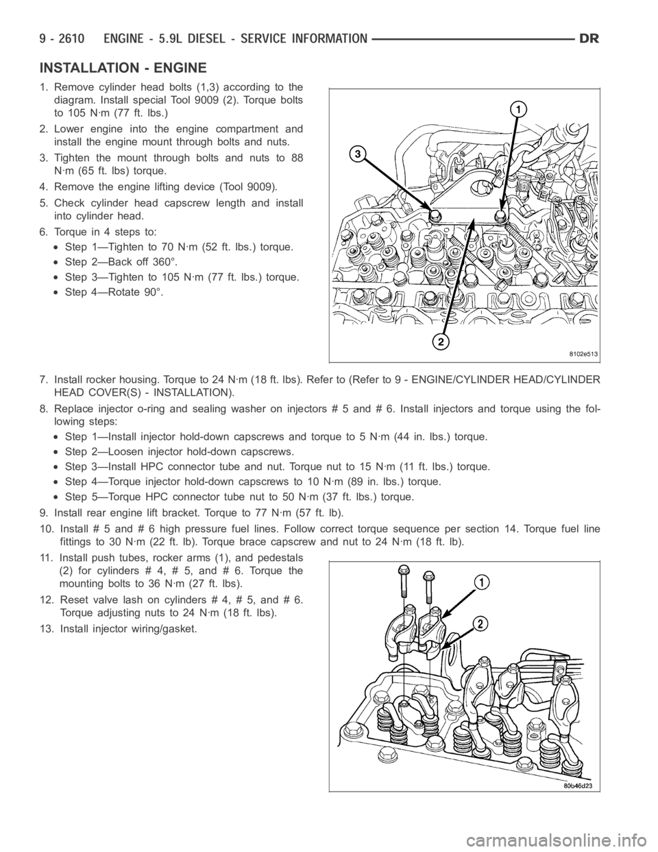
1. Remove cylinder head bolts (1,3) according to the
diagram. Install special Tool 9009 (2). Torque bolts
to 105 Nꞏm (77 ft. lbs.)
2. Lower engine into the engine compartment and
install the engine mount through bolts and nuts.
3. Tighten the mount through bolts and nuts to 88
Nꞏm (65 ft. lbs) torque.
4. Remove the engine lifting device (Tool 9009).
5. Check cylinder head capscrew length and install
into cylinder head.
6. Torque in 4 steps to:
Step 1—Tighten to 70 Nꞏm (52 ft. lbs.) torque.
Step 2—Back off 360°.
Step 3—Tighten to 105 Nꞏm (77 ft. lbs.) torque.
Step 4—Rotate 90°.
7. Install rocker housing. Torque to 24 Nꞏm (18 ft. lbs). Refer to (Refer to 9- ENGINE/CYLINDER HEAD/CYLINDER
HEAD COVER(S) - INSTALLATION).
8. Replace injector o-ring and sealing washer on injectors # 5 and # 6. Install injectors and torque using the fol-
lowing steps:
Step 1—Install injector hold-down capscrews and torque to 5 Nꞏm (44 in. lbs.) torque.
Step 2—Loosen injector hold-down capscrews.
Step 3—Install HPC connector tube and nut. Torque nut to 15 Nꞏm (11 ft. lbs.)torque.
Step 4—Torque injector hold-down capscrews to 10 Nꞏm (89 in. lbs.) torque.
Step 5—Torque HPC connector tube nut to 50 Nꞏm (37 ft. lbs.) torque.
9. Install rear engine lift bracket. Torque to 77 Nꞏm (57 ft. lb).
10. Install # 5 and # 6 high pressure fuel lines. Follow correct torque sequence per section 14. Torque fuel line
fittings to 30 Nꞏm (22 ft. lb). Torque brace capscrew and nut to 24 Nꞏm (18 ft.lb).
11. Install push tubes, rocker arms (1), and pedestals
(2) for cylinders # 4, # 5, and # 6. Torque the
mounting bolts to 36 Nꞏm (27 ft. lbs).
12. Reset valve lash on cylinders # 4, # 5, and # 6.
Torque adjusting nuts to 24 Nꞏm (18 ft. lbs).
13. Install injector wiring/gasket.
Page 1936 of 5267
INSPECTION
INSPECTION
Inspect the cylinder head for cracks in the combustion
surface. Pressure test any cylinder head that is visibly
cracked. A cylinder head that is cracked between the
injector bore and valve seat can be pressure tested
and reused if OK; however, if the crack extendsinto
the valve seat insert bore, the cylinder headmustbe
replaced.
Visually inspect the cylinder block and head combus-
tion surfaces for localized dips or imperfections. Check
the cylinder head and block combustion surfaces for
overall out-of-flatness. If either the visual or manual
inspection exceeds the limits, then the head or block
must be surfaced.
Check the top surface for damage caused by the cylinder head gasket leakingbetween cylinders.
Inspect the block and head surface for nicks, erosion, etc.
Check the head distortion. Maximum overall variation end to end is 0.305 mm(0.012 inch), and maximum overall
variationsidetoside0.076mm(.003in.).
DO NOT proceed with the in-chassis overhaul if the cylinder head or block surface is damaged or not flat (within
specifications).
Check block surface for distortion. Maximum variation end-to-end is 0.076 mm ( .003 in.), side-to-side 0.051 mm
(.002).
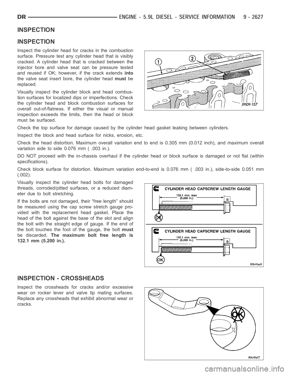
Visually inspect the cylinder head bolts for damaged
threads, corroded/pitted surfaces, or a reduced diam-
eter due to bolt stretching.
If the bolts are not damaged, their “free length” should
be measured using the cap screw stretch gauge pro-
vided with the replacement head gasket. Place the
head of the bolt against the base of the slot and align
the bolt with the straight edge of gauge. If the end of
the bolt touches the foot of the gauge, the boltmust
be discarded.The maximum bolt free length is
132.1 mm (5.200 in.).
INSPECTION - CROSSHEADS
Inspect the crossheads for cracks and/or excessive
wear on rocker lever and valve tip mating surfaces.
Replace any crossheads that exhibit abnormal wear or
cracks.
Page 1947 of 5267
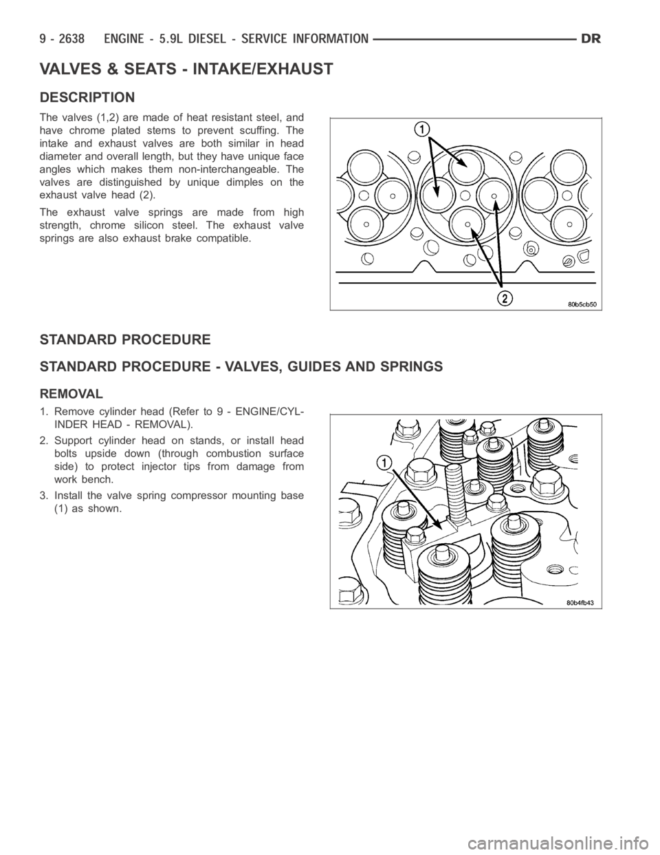
VALVES & SEATS - INTAKE/EXHAUST
DESCRIPTION
The valves (1,2) are made of heat resistant steel, and
have chrome plated stems to prevent scuffing. The
intake and exhaust valves are both similar in head
diameter and overall length, but they have unique face
angles which makes them non-interchangeable. The
valves are distinguished by unique dimples on the
exhaust valve head (2).
The exhaust valve springs are made from high
strength, chrome silicon steel. The exhaust valve
springs are also exhaust brake compatible.
STANDARD PROCEDURE
STANDARD PROCEDURE - VALVES, GUIDES AND SPRINGS
REMOVAL
1. Remove cylinder head (Refer to 9 - ENGINE/CYL-
INDER HEAD - REMOVAL).
2. Support cylinder head on stands, or install head
bolts upside down (through combustion surface
side) to protect injector tips from damage from
work bench.
3. Install the valve spring compressor mounting base
(1) as shown.
Page 1950 of 5267
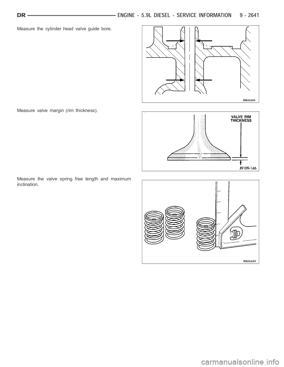
Measure the cylinder head valve guide bore.
Measure valve margin (rim thickness).
Measure the valve spring free length and maximum
inclination.
Page 1961 of 5267
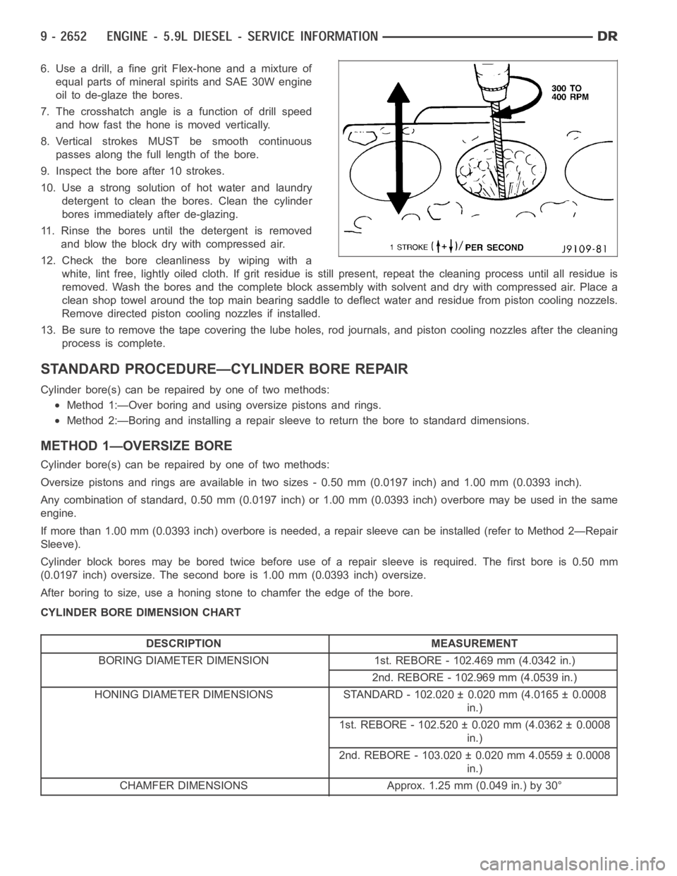
6. Use a drill, a fine grit Flex-hone and a mixture of
equal parts of mineral spirits and SAE 30W engine
oil to de-glaze the bores.
7. The crosshatch angle is a function of drill speed
and how fast the hone is moved vertically.
8. Vertical strokes MUST be smooth continuous
passes along the full length of the bore.
9. Inspect the bore after 10 strokes.
10. Use a strong solution of hot water and laundry
detergent to clean the bores. Clean the cylinder
bores immediately after de-glazing.
11. Rinse the bores until the detergent is removed
and blow the block dry with compressed air.
12. Check the bore cleanliness by wiping with a
white, lint free, lightly oiled cloth. If grit residue is still present, repeat the cleaning process until all residue is
removed. Wash the bores and the complete block assembly with solvent and dry with compressed air. Place a
clean shop towel around the top main bearing saddle to deflect water and residue from piston cooling nozzels.
Remove directed piston cooling nozzles if installed.
13. Be sure to remove the tape covering the lube holes, rod journals, and piston cooling nozzles after the cleaning
process is complete.
STANDARD PROCEDURE—CYLINDER BORE REPAIR
Cylinder bore(s) can be repaired by one of two methods:
Method 1:—Over boring and using oversize pistons and rings.
Method 2:—Boring and installing a repair sleeve to return the bore to standard dimensions.
METHOD 1—OVERSIZE BORE
Cylinder bore(s) can be repaired by one of two methods:
Oversize pistons and rings are available in two sizes - 0.50 mm (0.0197 inch) and 1.00 mm (0.0393 inch).
Any combination of standard, 0.50 mm (0.0197 inch) or 1.00 mm (0.0393 inch)overbore may be used in the same
engine.
If more than 1.00 mm (0.0393 inch) overbore is needed, a repair sleeve can beinstalled (refer to Method 2—Repair
Sleeve).
Cylinder block bores may be bored twice before use of a repair sleeve is required. The first bore is 0.50 mm
(0.0197 inch) oversize. The second bore is 1.00 mm (0.0393 inch) oversize.
After boring to size, use a honing stone to chamfer the edge of the bore.
CYLINDER BORE DIMENSION CHART
DESCRIPTION MEASUREMENT
BORING DIAMETER DIMENSION 1st. REBORE - 102.469 mm (4.0342 in.)
2nd. REBORE - 102.969 mm (4.0539 in.)
HONING DIAMETER DIMENSIONS STANDARD - 102.020 ± 0.020 mm (4.0165 ± 0.0008
in.)
1st. REBORE - 102.520 ± 0.020 mm (4.0362 ± 0.0008
in.)
2nd. REBORE - 103.020 ± 0.020 mm 4.0559 ± 0.0008
in.)
CHAMFER DIMENSIONS Approx. 1.25 mm (0.049 in.) by 30°
Page 1982 of 5267
TAPPETS - VALVE
REMOVAL
NOTE: This procedure requires use of Miller Tool
8502 Tappet Replacement Kit.
1. Remove camshaft (Refer to 9 - ENGINE/ENGINE
BLOCK/CAMSHAFT & BEARINGS (IN BLOCK) -
REMOVAL).
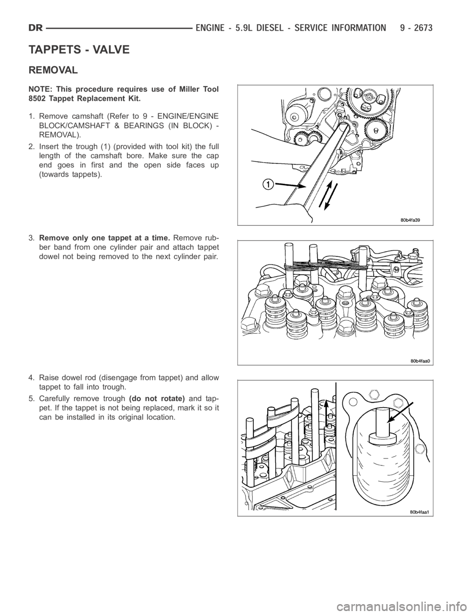
2. Insert the trough (1) (provided with tool kit) the full
length of the camshaft bore. Make sure the cap
end goes in first and the open side faces up
(towards tappets).
3.Remove only one tappet at a time.Remove rub-
ber band from one cylinder pair and attach tappet
dowel not being removed to the next cylinder pair.
4. Raise dowel rod (disengage from tappet) and allow
tappet to fall into trough.
5. Carefully remove trough(do not rotate)and tap-
pet. If the tappet is not being replaced, mark it so it
can be installed in its original location.
Page 1983 of 5267
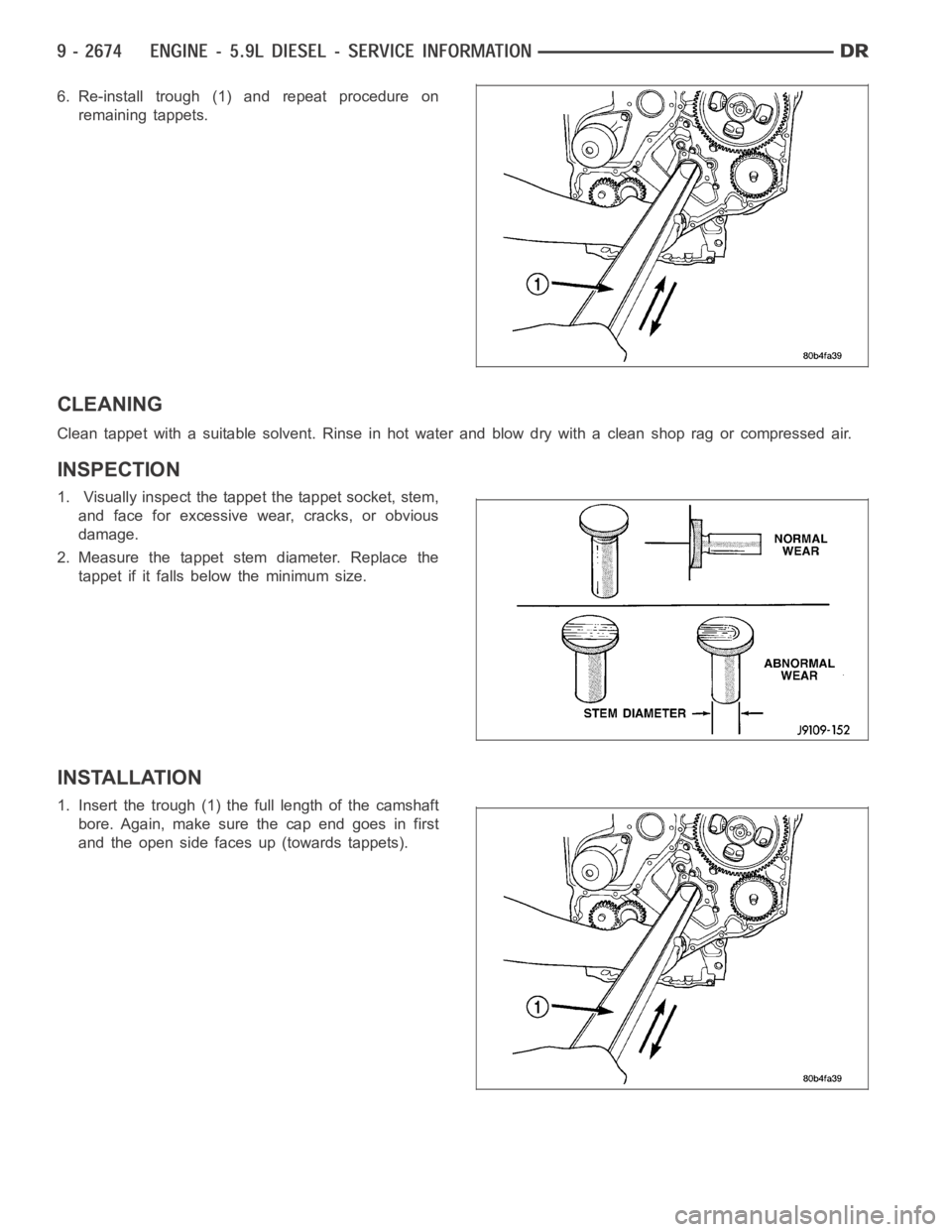
6. Re-install trough (1) and repeat procedure on
remaining tappets.
CLEANING
Clean tappet with a suitable solvent. Rinse in hot water and blow dry with a clean shop rag or compressed air.
INSPECTION
1. Visually inspect the tappet the tappet socket, stem,
and face for excessive wear, cracks, or obvious
damage.
2. Measure the tappet stem diameter. Replace the
tappet if it falls below the minimum size.
INSTALLATION
1. Insert the trough (1) the full length of the camshaft
bore. Again, make sure the cap end goes in first
and the open side faces up (towards tappets).
Page 1999 of 5267
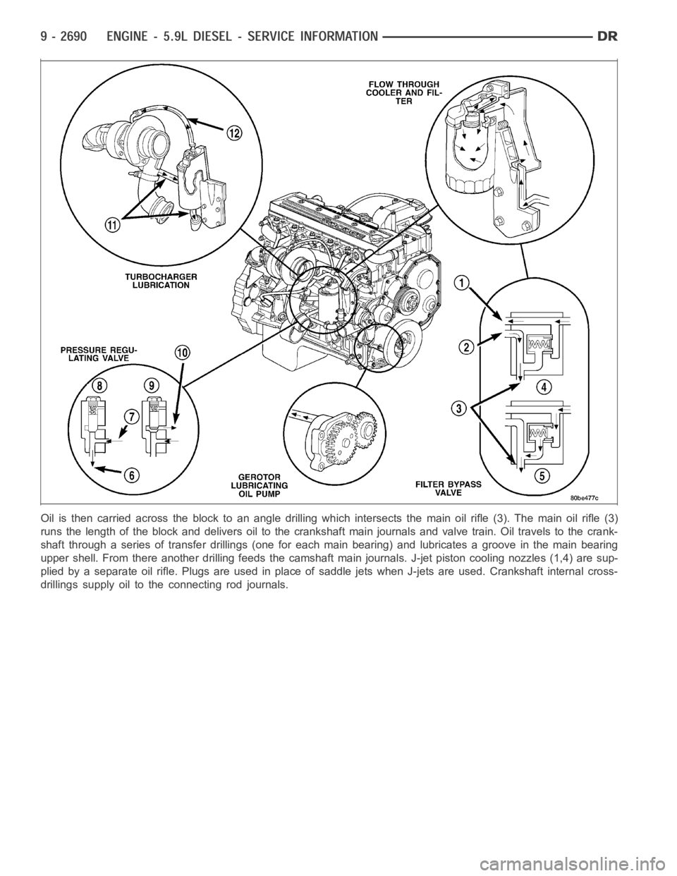
Oil is then carried across the block toan angle drilling which intersects the main oil rifle (3). The main oil rifle (3)
runs the length of the block and delivers oil to the crankshaft main journals and valve train. Oil travels to the crank-
shaft through a series of transfer drillings (one for each main bearing) and lubricates a groove in the main bearing
upper shell. From there another drilling feeds the camshaft main journals. J-jet piston cooling nozzles (1,4) are sup-
plied by a separate oil rifle. Plugs are used in place of saddle jets when J-jets are used. Crankshaft internal cross-
drillings supply oil to the connecting rod journals.