wheel DODGE RAM SRT-10 2006 Service User Guide
[x] Cancel search | Manufacturer: DODGE, Model Year: 2006, Model line: RAM SRT-10, Model: DODGE RAM SRT-10 2006Pages: 5267, PDF Size: 68.7 MB
Page 422 of 5267

U1418-IMPLAUSIBLE RIGHT WHEEL DISTANCE SIGNAL RECEIVED
For a complete wiring diagramRefer to Section 8W.
Page 423 of 5267
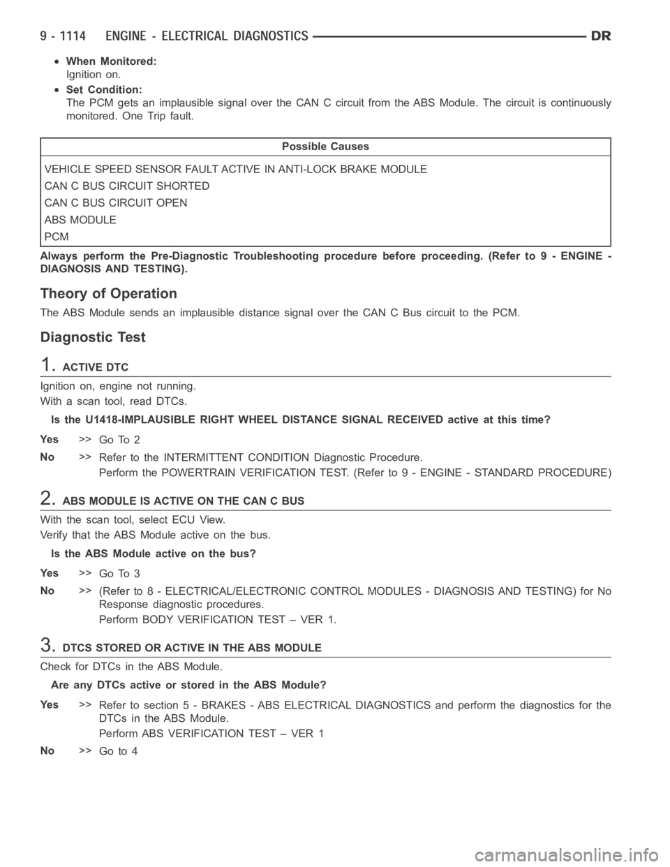
When Monitored:
Ignition on.
Set Condition:
The PCM gets an implausible signal over the CAN C circuit from the ABS Module. The circuit is continuously
monitored. One Trip fault.
Possible Causes
VEHICLE SPEED SENSOR FAULT ACTIVE IN ANTI-LOCK BRAKE MODULE
CAN C BUS CIRCUIT SHORTED
CAN C BUS CIRCUIT OPEN
ABS MODULE
PCM
Always perform the Pre-Diagnostic Troubleshooting procedure before proceeding. (Refer to 9 - ENGINE -
DIAGNOSIS AND TESTING).
Theory of Operation
The ABS Module sends an implausible distance signal over the CAN C Bus circuit to the PCM.
Diagnostic Test
1.ACTIVE DTC
Ignition on, engine not running.
With a scan tool, read DTCs.
Is the U1418-IMPLAUSIBLE RIGHT WHEEL DISTANCE SIGNAL RECEIVED active at this time?
Ye s>>
Go To 2
No>>
Refer to the INTERMITTENT CONDITION Diagnostic Procedure.
Perform the POWERTRAIN VERIFICATION TEST. (Refer to 9 - ENGINE - STANDARD PROCEDURE)
2.ABS MODULE IS ACTIVE ON THE CAN C BUS
With the scan tool, select ECU View.
Verify that the ABS Module active on the bus.
Is the ABS Module active on the bus?
Ye s>>
Go To 3
No>>
(Refer to 8 - ELECTRICAL/ELECTRONIC CONTROL MODULES - DIAGNOSIS AND TESTING) for No
Response diagnostic procedures.
Perform BODY VERIFICATION TEST – VER 1.
3.DTCS STORED OR ACTIVE IN THE ABS MODULE
Check for DTCs in the ABS Module.
Are any DTCs active or stored in the ABS Module?
Ye s>>
Refer to section 5 - BRAKES - ABS ELECTRICAL DIAGNOSTICS and perform the diagnostics for the
DTCs in the ABS Module.
Perform ABS VERIFICATION TEST – VER 1
No>>
Go to 4
Page 468 of 5267

When Monitored:
While Engine is running.
Set Condition:
When the engine speed detected by the Engine Position Sensor (cam) and the Engine Speed Sensor (crank)
differ by a specified RPM amount.
Possible Causes
DAMAGE TO THE ESS OR EPS
MECHANICAL MISALIGNMENT OF THE ESS OR EPS
MECHANICAL MISALIGNMENT OF THE CAMSHAFT AND CRANKSHAFT GEARS
INTERMITTENT CONDITION
Diagnostic Test
1.DAMAGE TO THE ESS OR EPS
Visually inspect the condition of the tone wheel, ESS, and EPS for damage.
Are any of the components damaged?
Ye s>>
Repair or replace any damaged component.
Perform POWERTRAIN VERIFICATION TEST VER - 1 (DIESEL). (Refer to 9 - ENGINE- DIAGNOSIS
AND TESTING)
No>>
Go To 2
2.MECHANICAL MISALIGNMENT OF THE ESS OR EPS
Verify the speed indicator ring is properly positioned relative to the locating pin in the front face of the crankshaft.
Is the speed indicator ring properly installed?
Ye s>>
Go To 3
No>>
Repair the speed ring indicator ring installation.
Perform POWERTRAIN VERIFICATION TEST VER - 1 (DIESEL). (Refer to 9 - ENGINE- DIAGNOSIS
AND TESTING)
3.MECHANICAL MISALIGNMENT OF THE CAMSHAFT AND CRANKSHAFT GEARS
Check the mechanical alignment of the camshaft gear to the crankshaft gear. Refer to service manual for assis-
tance.
Are the gear teeth in proper alignment?
Ye s>>
Refer to the INTERMITTENT CONDITION Symptom (Diagnostic Procedure). (Refer to 9 - ENGINE -
DIAGNOSIS AND TESTING)
No>>
Repair the gear alignment.
Perform POWERTRAIN VERIFICATION TEST VER - 1 (DIESEL). (Refer to 9 - ENGINE- DIAGNOSIS
AND TESTING)
Page 885 of 5267
3.INJECTION SYSTEM
Perform “*INJECTOR RETURN FLOW TEST”. If okay continue.
Check for correct injectors and injector shims.
Visuslly inspect injector wire nuts and pass through connectors for damageorcorrosion.
Is vehicle repaired?
Ye s>>
Repair complete.
Perform POWERTRAIN VERIFICATION TEST VER - 1 (DIESEL). (Refer to 8 - ELECTRICAL/ELEC-
TRONIC CONTROL MODULES/ENGINE CONTROL MODULE - DIAGNOSIS AND TESTING)
No>>
Go To 4
4.FUEL RETURN
Check for kinked or restricted fuel return lines.
Check fuel tank venting.
Is vehicle repaired?
Ye s>>
Repair complete.
Perform POWERTRAIN VERIFICATION TEST VER - 1 (DIESEL). (Refer to 8 - ELECTRICAL/ELEC-
TRONIC CONTROL MODULES/ENGINE CONTROL MODULE - DIAGNOSIS AND TESTING)
No>>
Go To 5
5.INTAKE SYSTEM
Check for inlet restriction, inspect air filter for excessive dirt/debris. Verify air intake lines are not kinked or restricted.
Check for air system leaks. Perform “*INTAKE AIR SYSTEM PRESSURE TEST - DIESEL”.
Inspect Turbocharger for wheel clearance and proper wastegate operation.
Is vehicle repaired?
Ye s>>
Repair complete.
Perform POWERTRAIN VERIFICATION TEST VER - 1 (DIESEL). (Refer to 8 - ELECTRICAL/ELEC-
TRONIC CONTROL MODULES/ENGINE CONTROL MODULE - DIAGNOSIS AND TESTING)
No>>
Go To 6
6.OTHER VEHICLE SYSTEMS
Verify proper operation of the Transmission Clutch.
Verify proper operation of the Transmission.
Verify proper operation of the Vehicle brakes (check for dragging).
Verify proper operation of the Cooling fan operation cycle time.
Verify proper operation of the Engine driven accessories.
Verify proper operation of the Accelerator pedal (restricted or out of calibration).
Is vehicle repaired?
Ye s>>
Repair complete.
Perform POWERTRAIN VERIFICATION TEST VER - 1 (DIESEL). (Refer to 8 - ELECTRICAL/ELEC-
TRONIC CONTROL MODULES/ENGINE CONTROL MODULE - DIAGNOSIS AND TESTING)
No>>
Go To 7
Page 889 of 5267
8.INTAKE SYSTEM
Check for inlet restriction, inspect air filter for excessive dirt/debris. Verify air intake lines are not kinked or restricted.
Check for air system leaks. Perform “*INTAKE AIR SYSTEM PRESSURE TEST - DIESEL”.
Inspect Turbocharger for wheel clearance and proper wastegate operation.
Check for exhaust restriction. Verify proper exhaust brake operation. Check for kinked or blocked exhaust pipes.
Is vehicle repaired?
Ye s>>
Repair complete.
Perform POWERTRAIN VERIFICATION TEST VER - 1 (DIESEL). (Refer to 8 - ELECTRICAL/ELEC-
TRONIC CONTROL MODULES/ENGINE CONTROL MODULE - DIAGNOSIS AND TESTING)
No>>
Go To 9
9.OTHER VEHICLE SYSTEMS
Verify proper operation of the Transmission Clutch.
Verify proper operation of the Transmission.
Verify proper operation of the Vehicle brakes (check for dragging).
Verify proper operation of the Cooling fan operation cycle time.
Verify proper operation of the Engine driven accessories.
Verify proper operation of the Accelerator pedal (restricted or out of calibration).
Verify no excess Electrical Noise.
Verify no Moisture in harness connector or corroded terminals.
Is vehicle repaired?
Ye s>>
Repair complete.
Perform POWERTRAIN VERIFICATION TEST VER - 1 (DIESEL). (Refer to 8 - ELECTRICAL/ELEC-
TRONIC CONTROL MODULES/ENGINE CONTROL MODULE - DIAGNOSIS AND TESTING)
No>>
Go To 7
10.BASE ENGINE
Inspect speed indicator ring for damaged/missing teeth.
Check for internal engine damage.
Repair Complete.
Ye s>>
Repair complete.
Perform POWERTRAIN VERIFICATION TEST VER - 1 (DIESEL). (Refer to 8 - ELECTRICAL/ELEC-
TRONIC CONTROL MODULES/ENGINE CONTROL MODULE - DIAGNOSIS AND TESTING)
Page 1225 of 5267
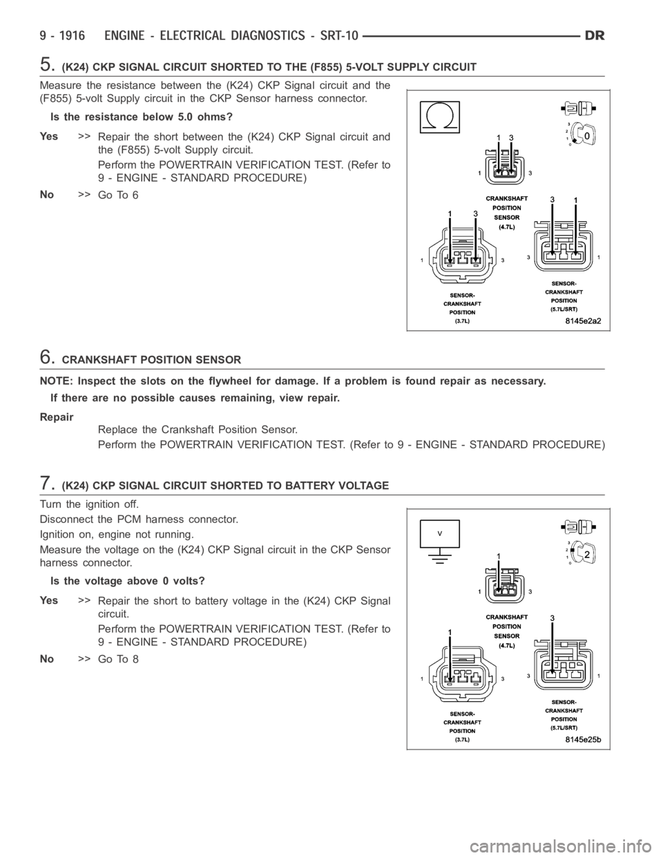
5.(K24) CKP SIGNAL CIRCUIT SHORTED TO THE (F855) 5-VOLT SUPPLY CIRCUIT
Measure the resistance between the (K24) CKP Signal circuit and the
(F855) 5-volt Supply circuit in the CKP Sensor harness connector.
Is the resistance below 5.0 ohms?
Ye s>>
Repair the short between the (K24) CKP Signal circuit and
the (F855) 5-volt Supply circuit.
Perform the POWERTRAIN VERIFICATION TEST. (Refer to
9 - ENGINE - STANDARD PROCEDURE)
No>>
Go To 6
6.CRANKSHAFT POSITION SENSOR
NOTE: Inspect the slots on the flywheel for damage. If a problem is found repair as necessary.
If there are no possible causes remaining, view repair.
Repair
Replace the Crankshaft Position Sensor.
Perform the POWERTRAIN VERIFICATION TEST. (Refer to 9 - ENGINE - STANDARD PROCEDURE)
7.(K24) CKP SIGNAL CIRCUIT SHORTED TO BATTERY VOLTAGE
Turn the ignition off.
Disconnect the PCM harness connector.
Ignition on, engine not running.
Measure the voltage on the (K24) CKP Signal circuit in the CKP Sensor
harness connector.
Is the voltage above 0 volts?
Ye s>>
Repair the short to battery voltage in the (K24) CKP Signal
circuit.
Perform the POWERTRAIN VERIFICATION TEST. (Refer to
9 - ENGINE - STANDARD PROCEDURE)
No>>
Go To 8
Page 1410 of 5267
When Monitored:
Engine running or cranking.
Set Condition:
When the failure counter reaches 20 for 2 consecutive trips.
Possible Causes
GOOD TRIP EQUAL TO ZERO
CMP WIRE HARNESS INSPECTION
TONE WHEEL/PULSE RING INSPECTION
CKP WIRE HARNESS INSPECTION
TONE WHEEL/PULSE RING INSPECTION
CHECKING INTERMITTENT CKP SIGNAL WITH LAB SCOPE
CAMSHAFT POSITION SENSOR
CRANKSHAFT POSITION SENSOR
Always perform the Pre-Diagnostic Troubleshooting procedure before proceeding. (Refer to 9 - ENGINE -
DIAGNOSIS AND TESTING)
1.GOOD TRIP EQUAL TO ZERO
Ignition on, engine not running.
WARNING: When the engine is operating, do not stand in a direct line with thefan. Do not put your hand
near the pulleys, belts, or fan. Do not wear loose clothing.
With the scan tool, read DTCs and record the related Freeze Frame data.
Start the engine and run until operating temp is reached. (Closed Loop)
If the DTC does not return right away it may be necessary to test drive the vehicle to duplicate the DTC.
Does the P1391 return?
Ye s>>
Go To 2
No>>
Refer to the INTERMITTENT CONDITIONSymptom (Diagnostic Procedure).
Perform POWERTRAIN VERIFICATION TEST. (Refer to 9 - ENGINE - STANDARD PROCEDURE)
2.INTERMITTENT CAM POSITION SENSOR SIGNAL
Turn the ignition off.
With the scan tool as a Dual Channel Lab Scope and Miller special tool #6801,backprobe the (K44) CMP Signal
circuit in the CMP harness connector and PCM harness connector.
WARNING: When the engine is operating, do not stand in a direct line with thefan. Do not put your hand
near the pulleys, belts, or fan. Do not wear loose clothing.
Start the engine.
Observe the lab scope screen.
Are there any irregular or missing signals?
Ye s>>
Go To 3
No>>
Go To 6
Page 1411 of 5267
3.CMP WIRE HARNESS INSPECTION
Visually inspect the related wire harness. Look for any chafed, pierced, pinched, or partially broken wires.
Visually inspect the related wire harness connectors. Look for broken, bent, pushed out, or corroded terminals.
Make sure the Crankshaft Position Sensor and the Camshaft Position Sensorare properly installed and the mount-
ing bolt(s) are torqued to specification.
Refer to any TSB that may apply.
Were any of the above conditions present?
Ye s>>
Repair as necessary
Perform POWERTRAIN VERIFICATION TEST. (Refer to 9 - ENGINE - STANDARD PROCEDURE)
No>>
Go To 4
4.TONE WHEEL/PULSE RING INSPECTION
Turn the ignition off.
Remove the Camshaft Position Sensor.
Inspect the Tone Wheel/Pulse Ring for damage, foreign material, or excessive movement.
Were any problems found?
Ye s>>
Repair or replace the Tone Wheel/Pulse Ring as necessary.
Perform POWERTRAIN VERIFICATION TEST. (Refer to 9 - ENGINE - STANDARD PROCEDURE)
No>>
Go To 5
5.CAMSHAFT POSITION SENSOR
If there are no possible causes remaining, view repair.
Repair
Replace the Camshaft Position Sensor.
Perform POWERTRAIN VERIFICATION TEST. (Refer to 9 - ENGINE - STANDARD PROCEDURE)
6.CHECKING CKP SIGNAL WITH THE SCAN TOOL LAB
Turn the ignition off.
With the scan tool as a Dual Channel Lab Scope and the Miller special tool #6801, backprobe the (K24) CKP Signal
circuit in the CKP harness connector and PCM harness connector.
WARNING: When the engine is operating, do not stand in a direct line with thefan. Do not put your hand
near the pulleys, belts, or fan. Do not wear loose clothing.
Start the engine.
Observe the lab scope screen.
Are there any irregular or missing signals?
Ye s>>
Go To 7
No>>
Go To 10
Page 1412 of 5267
7.CKP WIRE HARNESS INSPECTION
Visually inspect the related wire harness. Look for any chafed, pierced, pinched, or partially broken wires.
Visually inspect the related wire harness connectors. Look for broken, bent, pushed out, or corroded terminals.
Ensure the Crankshaft Position Sensor and the Camshaft Position Sensor are properly installed and the mounting
bolt(s) are torqued to specification.
Refer to any TSB that may apply.
Were any of the above conditions present?
Ye s>>
Repair as necessary
Perform POWERTRAIN VERIFICATION TEST. (Refer to 9 - ENGINE - STANDARD PROCEDURE)
No>>
Go To 8
8.TONE WHEEL/FLEX PLATE INSPECTION
Remove the Crankshaft Position Sensor.
Inspect the Tone Wheel/Flex Plate slots for damage, foreign material, or excessive movement.
Were any problems found?
Ye s>>
Repair or replace the Tone Wheel/Flex Plate as necessary.
Perform POWERTRAIN VERIFICATION TEST. (Refer to 9 - ENGINE - STANDARD PROCEDURE)
No>>
Go To 9
9.CRANKSHAFT POSITION SENSOR
If there are no possible causes remaining, view repair.
Repair
Replace the Crankshaft Position Sensor.
Perform POWERTRAIN VERIFICATION TEST. (Refer to 9 - ENGINE - STANDARD PROCEDURE)
10.CHECKING CKP SIGNAL WITH LAB SCOPE
NOTE: The conditions that set this DTC are not present at this time. The following test may help in identi-
fying the intermittent condition.
Turn the ignition off.
With the scan tool as a Dual Channel Lab Scope and the Miller special tool #6801, backprobe the (K24) CKP Signal
circuit in the PCM harness connector and CKP harness connector.
WARNING: When the engine is operating, do not stand in a direct line with thefan. Do not put your hand
near the pulleys, belts, or fan. Do not wear loose clothing.
Start the engine.
Carefully wiggle the related wire harness and gently tap on the CKP sensor.
Compare the Channel 1 reading to the Channel 2 reading on the lab scope screen.
Both of the readings should be the same.
Were any of the above conditions present?
Ye s>>
Repair the wiring or connector concern.
Perform POWERTRAIN VERIFICATION TEST. (Refer to 9 - ENGINE - STANDARD PROCEDURE)
No>>
Te s t C o m p l e t e .
Page 1413 of 5267
P1398-MIS-FIRE ADAPTIVE NUMERATOR AT LIMIT
For a complete wiring diagramRefer to Section 8W.
When Monitored:
Under closed throttle decel and Fuel Pulse Width equal to zero for 30 seconds.
Set Condition:
One of the CKP sensor target windows has more than 2.86% variance from the reference window.
Possible Causes
ADAPTIVE NUMERATOR RELEARN
CMP SENSOR CONNECTOR/WIRING
CKP SENSOR CONNECTOR/WIRING
DAMAGED TONE WHEEL/FLEX PLATE (CRANKSHAFT)
CRANKSHAFT POSITION SENSOR
PCM
Always perform the Pre-Diagnostic Troubleshooting procedure before proceeding. (Refer to 9 - ENGINE -
DIAGNOSIS AND TESTING)
1.ADAPTIVE NUMERATOR RELEARN
NOTE: Check for any TSB’s that may apply to this symptom.
Read and record the Freeze Frame Data. Use this information to help you duplicate the conditions that set the DTC.
Pay particular attention to the DTC set conditions, such as, VSS, MAP, ECT,and Load.
Ignition on, engine not running.
With the scan tool in the miscellaneous menu, choose Clear PCM (battery disconnect) to reset the PCM.
With the scan tool, choose the Misfire Pretest screen.
Road test the vehicle and re-learn the adaptive numerator.
The adaptive numerator is learned when the Adaptive Numerator Done Learning line on the Misfire screen changes
to Yes.
Did the adaptive numerator re-learn?
Ye s>>
Refer to the INTERMITTENT CONDITIONSymptom (Diagnostic Procedure).
Perform POWERTRAIN VERIFICATION TEST. (Refer to 9 - ENGINE - STANDARD PROCEDURE)
No>>
Go To 2
2.CMP CONNECTOR/HARNESS INSPECTION
Turn ignition off.
NOTE: Visually inspect the related wire harness connectors. Look for broken, bent, pushed out, or corroded
terminals.
NOTE: Visually inspect the related wire harness. Look for any chafed, pierced, pinched, or partially broken
wires.
NOTE: Make sure the Camshaft Position Sensor is tight.
NOTE: Refer to any technical service bulletins that may apply.
Were any problems found?
Ye s>>
Repair as necessary.
Perform POWERTRAIN VERIFICATION TEST. (Refer to 9 - ENGINE - STANDARD PROCEDURE)
No>>
Go To 3