Fuel injector removal DODGE RAM SRT-10 2006 Service Owner's Manual
[x] Cancel search | Manufacturer: DODGE, Model Year: 2006, Model line: RAM SRT-10, Model: DODGE RAM SRT-10 2006Pages: 5267, PDF Size: 68.7 MB
Page 2262 of 5267
1. Remove fuel tank filler tube cap.
2. Perform fuel system pressure release procedure.
(Refer to 14 - FUEL SYSTEM/FUEL DELIVERY -
STANDARD PROCEDURE)
3. Remove negative battery cable at battery.
4. Remove flex tube (air cleaner housing to engine).
5. Remove air resonator box at throttle body.
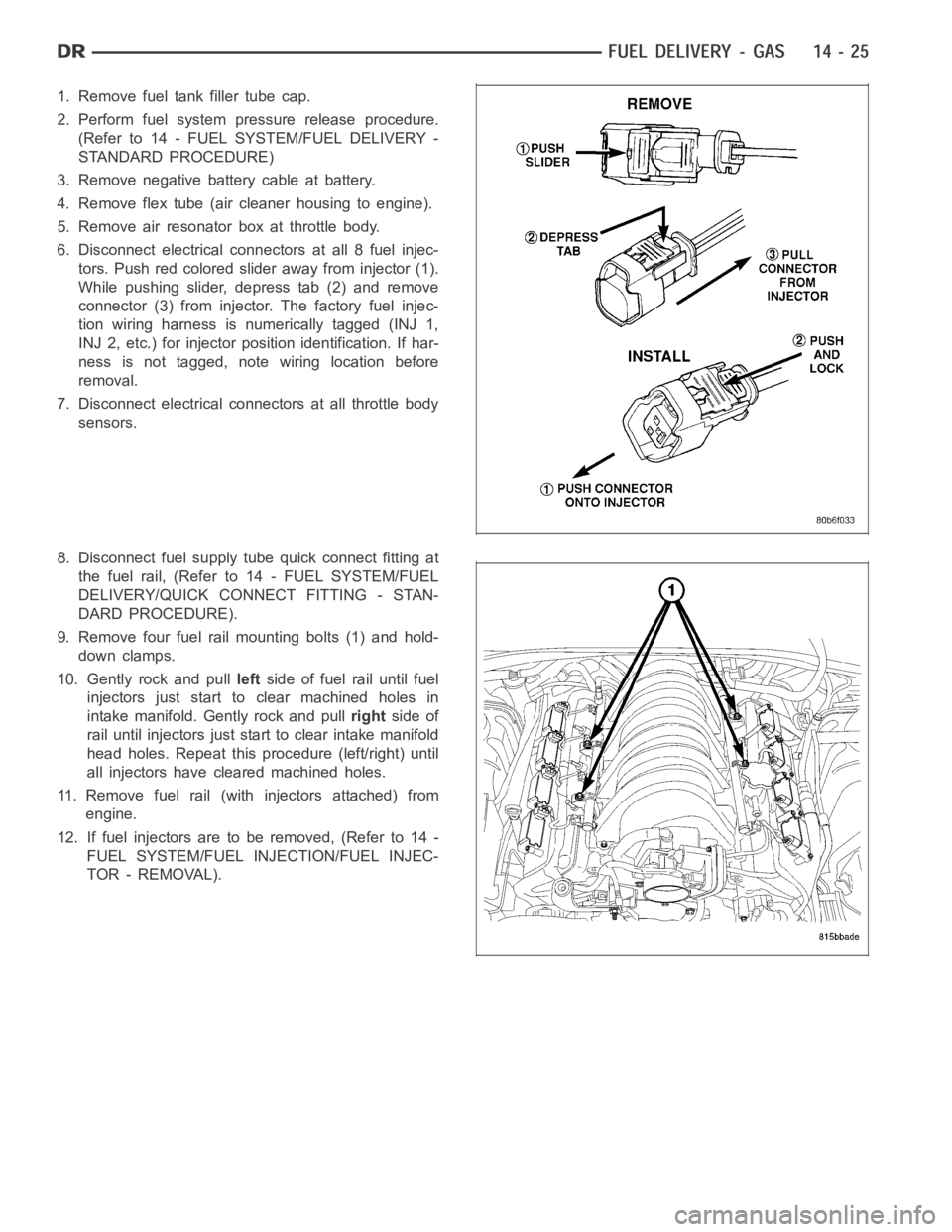
6. Disconnect electrical connectors at all 8 fuel injec-
tors. Push red colored slider away from injector (1).
While pushing slider, depress tab (2) and remove
connector (3) from injector. The factory fuel injec-
tion wiring harness is numerically tagged (INJ 1,
INJ 2, etc.) for injector position identification. If har-
ness is not tagged, note wiring location before
removal.
7. Disconnect electrical connectors at all throttle body
sensors.
8. Disconnect fuel supply tube quick connect fitting at
the fuel rail, (Refer to14 - FUEL SYSTEM/FUEL
DELIVERY/QUICK CONNECT FITTING - STAN-
DARD PROCEDURE).
9. Remove four fuel rail mounting bolts (1) and hold-
down clamps.
10. Gently rock and pullleftside of fuel rail until fuel
injectors just start to clear machined holes in
intake manifold. Gently rock and pullrightside of
rail until injectors just start to clear intake manifold
head holes. Repeat this procedure (left/right) until
all injectors have cleared machined holes.
11. Remove fuel rail (with injectors attached) from
engine.
12. If fuel injectors are to be removed, (Refer to 14 -
FUEL SYSTEM/FUEL INJECTION/FUEL INJEC-
TOR - REMOVAL).
Page 2281 of 5267
page page
PEDAL - ACCELERATOR
REMOVAL .................................... 46
INSTALLATION ............................... 46
SENSOR-ACCELERATOR PEDAL POSITION
DESCRIPTION ................................ 47
OPERATION .................................. 47
REMOVAL .................................... 47
INSTALLATION ............................... 48
SENSOR-CRANKSHAFT POSITION
DESCRIPTION
3.7L V-6 .................................... 49
4.7L V-8 .................................... 49
5.7L V-8 .................................... 50
OPERATION
3.7L V-6 .................................... 50
4.7L V-8 .................................... 51
5.7L V-8 .................................... 51
REMOVAL
3.7L V-6 .................................... 52
4.7L V-8 .................................... 52
5.7L V-8 .................................... 53
8.3L - SRT-10 ............................... 53
INSTALLATION
3.7L V-6 .................................... 54
4.7L V-8 .................................... 55
5.7L V-8 .................................... 55
8.3L - SRT-10 ............................... 55
INJECTOR - FUEL
DESCRIPTION ................................ 56
OPERATION
FUEL INJECTOR ............................ 56
PCM OUTPUT .............................. 56
REMOVAL
3.7/4.7/ 5.7L ................................ 57
8.3L - SRT-10 ............................... 57
INSTALLATION
3.7/ 4.7/ 5.7L ............................... 60
8.3L - SRT-10 ............................... 60
RELAY - FUEL PUMP
DESCRIPTION ................................ 61
OPERATION .................................. 61
REMOVAL .................................... 61
INSTALLATION ............................... 61
MOTOR-IAC
DESCRIPTION
3.7L, 4.7L, 5.7L ............................. 62
8.3L - SRT-10 ............................... 63
OPERATION
3.7L V-6/4.7L V-8 ............................ 63
REMOVAL
3.7L V-6 .................................... 644.7L V-8 .................................... 65
5.7L V-8 .................................... 65
8.3L - SRT-10 ............................... 65
INSTALLATION
3.7L V-6 .................................... 66
4.7L V-8 .................................... 66
5.7L V-8 .................................... 66
8.3L - SRT-10 ............................... 67
SENSOR - INLET AIR TEMPERATURE
REMOVAL — 8.3L ............................. 68
INSTALLATION ............................... 68
SENSOR-INTAKE AIR TEMPERATURE
DESCRIPTION
3.7L V-6 .................................... 69
4.7L V-8 .................................... 69
5.7L V-8 .................................... 70
OPERATION .................................. 70
REMOVAL
3.7L V-6 .................................... 71
4.7L V-8 .................................... 72
5.7L V-8 .................................... 73
INSTALLATION
3.7L V-6 .................................... 74
4.7L V-8 .................................... 75
5.7L V-8 .................................... 75
SENSOR-MAP
DESCRIPTION
3.7L V-6 .................................... 76
4.7L V-8 .................................... 76
5.7L V-8 .................................... 77
8.3L - SRT-10 ............................... 77
OPERATION .................................. 77
REMOVAL
3.7L V-6 .................................... 79
4.7L V-8 .................................... 80
5.7L V-8 .................................... 80
8.3 L - SRT-10 .............................. 81
INSTALLATION
3.7L V-6 .................................... 81
4.7L V-8 .................................... 82
5.7L V-8 .................................... 83
8.3L - SRT-10 ............................... 83
SENSOR - OXYGEN
DESCRIPTION ................................ 84
REMOVAL .................................... 84
INSTALLATION ............................... 85
SWITCH-PTO
DESCRIPTION ................................ 86
OPERATION .................................. 86
THROTTLE BODY
DESCRIPTION ................................ 87
Page 2294 of 5267
Battery voltage (12 volts +) is supplied to the injectors through the ASD relay. The ASD relay will shut-down the 12
volt power source to the fuel injectors if the PCM senses the ignition is on,but the engine is not running. This
occurs after the engine has not been running for approximately 1.8 seconds.
The PCM determines injector on-time (pulse width) based on various inputs.
REMOVAL
3.7/4.7/ 5.7L
1. Remove fuel rail. (Refer to 14 - FUEL SYSTEM/
FUEL DELIVERY/FUEL RAIL - REMOVAL)
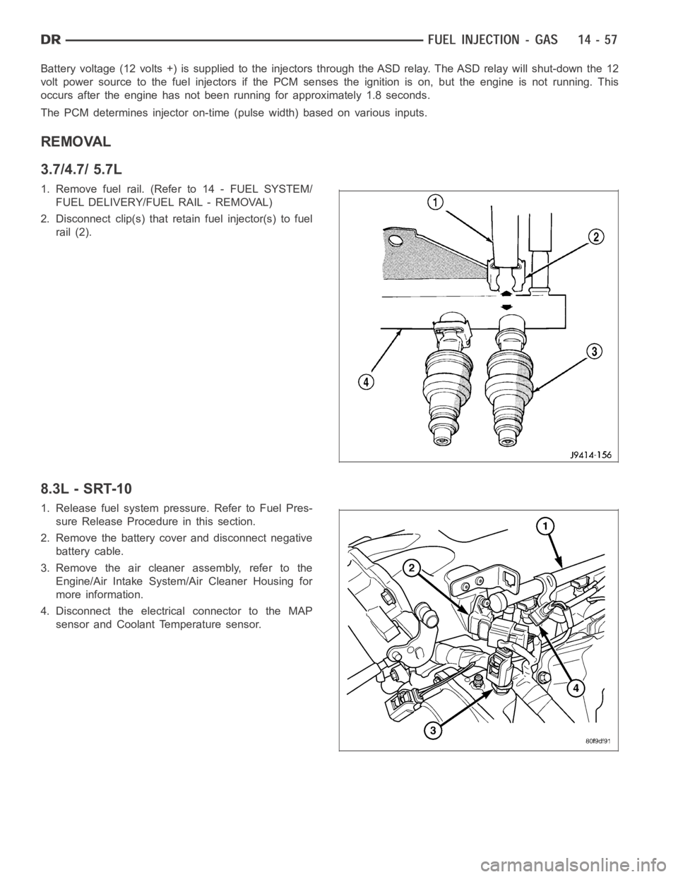
2. Disconnect clip(s) that retain fuel injector(s) to fuel
rail (2).
8.3L - SRT-10
1. Release fuel system pressure. Refer to Fuel Pres-
sure Release Procedure in this section.
2. Remove the battery cover and disconnect negative
battery cable.
3. Remove the air cleaner assembly, refer to the
Engine/Air Intake System/Air Cleaner Housing for
more information.
4. Disconnect the electrical connector to the MAP
sensor and Coolant Temperature sensor.
Page 2324 of 5267
THROTTLE BODY
DESCRIPTION
The throttle body is located on the intake manifold. Fuel does not enter theintake manifold through the throttle body.
Fuel is sprayed into the manifold by the fuel injectors.
OPERATION
Filtered air from the air cleaner enters the intake manifold through the throttle body. The throttle body contains an air
control passage controlled by an Idle Air Control (IAC) motor. The air control passage is used to supply air for idle
conditions. A throttle valve (plate) is used to supply air for above idle conditions.
5.7L V-8 Engine:
The throttle body on the 5.7L engine is an electrically controlled unit. A mechanical cable is not used to connect the
throttle body to the accelerator pedal. The Accelerator Pedal Position Sensor (APPS) along with inputs from other
sensors sets the throttle blade to pre-determined positions.
Except 5.7L V-8 Engine:
Certain sensors are attached to the throttle body. The accelerator pedal cable, speed control cable and transmission
control cable (when equipped) are connected to the throttle body linkage arm.
A (factory adjusted) set screw is usedto mechanically limit the position of the throttle body throttle plate.Never
attempt to adjust the engine idle speed using this screw.All idle speed functions are controlled by the PCM.
REMOVAL
3.7L V-6
A (factory adjusted) set screw is used to mechanically
limit the position of the throttle body throttle plate.
Never attempt to adjust the engine idle speed
using this screw.All idle speed functions are con-
trolled by the Powertrain Control Module (PCM).
1. Remove air cleaner tube at throttle body.
2. Disconnect throttle body electrical connectors at
IAC motor and TPS.
3. Remove all control cables from throttle body (lever)
arm. Refer to the Accelerator Pedal and Throttle
Cable section for removal/installation procedures.
4. Disconnect necessary vacuum lines at throttle
body.
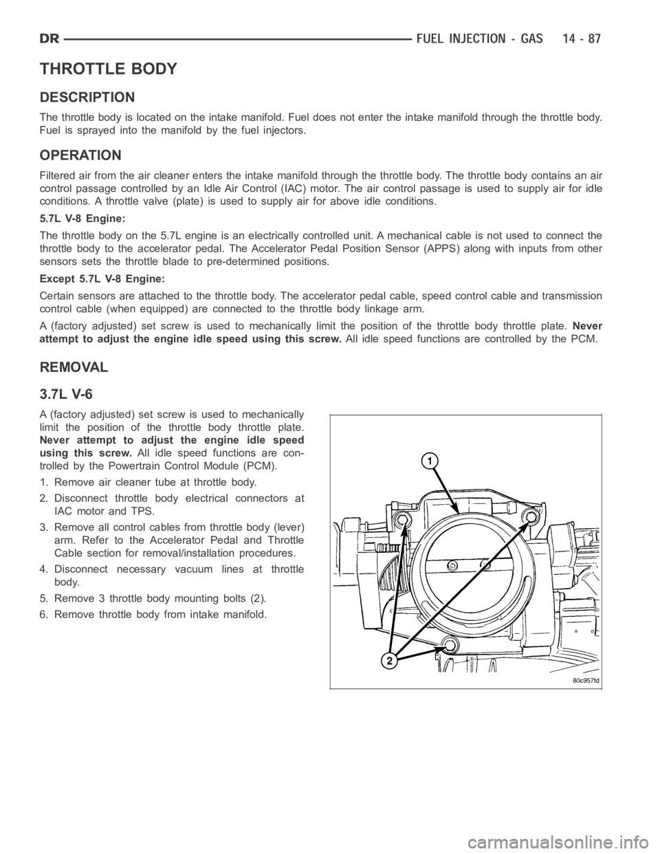
5. Remove 3 throttle body mounting bolts (2).
6. Remove throttle body from intake manifold.
Page 2336 of 5267
OPERATION
The 5.7L V-8 engine does not use a separate Throttle Position Sensor (TPS) on the throttle body.
The 3-wire TPS provides the Powertrain Control Module (PCM) with an input signal (voltage) that represents the
throttle blade position of the throttle body. The sensor is connected to the throttle blade shaft. As the position of the
throttle blade changes, the output voltage of the TPS changes.
The PCM supplies approximately 5 volts to the TPS. The TPS output voltage (input signal to the PCM) represents
the throttle blade position. The PCM receives an input signal voltage fromthe TPS. This will vary in an approximate
range of from .26 volts at minimum throttle opening (idle), to 4.49 volts atwide open throttle. Along with inputs from
other sensors, the PCM uses the TPS input to determine current engine operating conditions. In response to engine
operating conditions, the PCM will adjust fuel injector pulse width and ignition timing.
The PCM needs to identify the actions and position of the throttle blade at all times. This information is needed to
assist in performing the following calculations:
Ignition timing advance
Fuel injection pulse-width
Idle (learned value or minimum TPS)
Off-idle (0.06 volt)
Wide Open Throttle (WOT) open loop (2.608 volts above learned idle voltage)
Deceleration fuel lean out
Fuel cutoff during cranking at WOT (2.608 volts above learned idle voltage)
A/C WOT cutoff (certain automatic transmissions only)
REMOVAL
3.7L V6
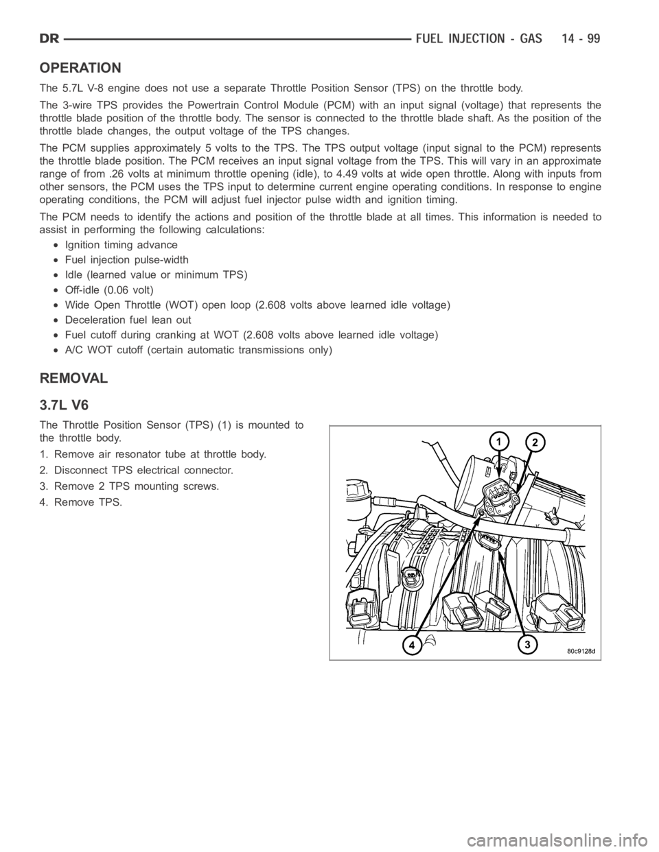
The Throttle Position Sensor (TPS) (1) is mounted to
the throttle body.
1. Remove air resonator tube at throttle body.
2. Disconnect TPS electrical connector.
3. Remove 2 TPS mounting screws.
4. Remove TPS.
Page 2341 of 5267
page page
FUEL DELIVERY - DIESEL
DESCRIPTION - DIESEL FUEL SYSTEM ....... 105
STANDARD PROCEDURE
WATER DRAINING AT FUEL FILTER ......... 106
CLEANING FUEL SYSTEM PARTS .......... 106
FUEL SYSTEM PRIMING................... 106
DRAINING FUEL TANK - DIESEL............ 107
SPECIFICATIONS
FUEL INJECTOR FIRING ORDER - DIESEL . . 107
TORQUE .................................. 107
SPECIAL TOOLS
DIESEL FUEL SYSTEM . .................... 109
FILTER - FUEL / WATER SEPARATOR
DESCRIPTION ............................... 111
OPERATION ................................. 111
REMOVAL ................................... 111
INSTALLATION .............................. 113
HEATER-FUEL
DESCRIPTION ............................... 115
OPERATION ................................. 115
DIAGNOSIS AND TESTING
FUEL HEATER ............................. 115
REMOVAL ................................... 116
PUMP - FUEL INJECTION
DESCRIPTION ............................... 117
OPERATION ................................. 117
DIAGNOSIS AND TESTING
FUEL INJECTION PUMP TIMING ............ 117
REMOVAL ................................... 117
INSTALLATION .............................. 120
SENSOR - FUEL LEVEL SENDING UNIT
DESCRIPTION ............................... 124
OPERATION ................................. 124
REMOVAL
REMOVAL/INSTALLATION .................. 124
LINES - FUEL
DESCRIPTION ............................... 125
OPERATION ................................. 125DIAGNOSIS AND TESTING
HIGH-PRESSURE FUEL LINE LEAKS........ 125
REMOVAL ................................... 126
INSTALLATION .............................. 127
SENSOR - FUEL PRESSURE
DESCRIPTION ............................... 129
OPERATION ................................. 129
REMOVAL ................................... 129
INSTALLATION .............................. 129
VALVE - FUEL PRESSURE LIMITING
DESCRIPTION ............................... 130
OPERATION ................................. 130
REMOVAL ................................... 130
INSTALLATION .............................. 131
TA N K - F U E L
DESCRIPTION ............................... 132
REMOVAL ................................... 132
INSTALLATION .............................. 133
MODULE - FUEL TANK
DESCRIPTION ............................... 134
OPERATION ................................. 134
REMOVAL ................................... 134
INSTALLATION .............................. 134
PUMP - FUEL TRANSFER
DESCRIPTION ............................... 136
OPERATION ................................. 136
REMOVAL ................................... 136
INSTALLATION .............................. 136
VALVE - CASCADE OVERFLOW
DESCRIPTION ............................... 137
OPERATION ................................. 137
SENSOR-WATER IN FUEL
DESCRIPTION ............................... 138
OPERATION ................................. 138
REMOVAL ................................... 138
CIRCUIT - FUEL DRAIN
OPERATION ................................. 139
Page 2343 of 5267
Fuel enters the system from the electric fuel transfer (lift) pump, which is located inside of the fuel tank and attached
to the fuel tank module (the fuel transfer pump is no longer attached to the engine). Fuel is forced through the fuel
filter element and then enters the Fuel Pump/Gear Pump, which is attached to the rear of the fuel injection pump.
The Fuel Pump/Gear Pump is a low-pressure pump and produce pressures ranging from 551.5 kpa (80 psi) to 1241
kpa (180) psi. Fuel then enters the fuel injection pump. Low pressure fuel is then supplied to the FCA (Fuel Control
Actuator).
The FCA is an electronically controlled solenoid valve. The ECM controls the amount of fuel that enters the high-
pressure pumping chambers by opening and closing the FCA based on a demanded fuel pressure. The FPS (Fuel
Pressure Sensor) on the fuel rail monitors the actual fuel pressure and provides it as an input to the ECM. When
the actuator is opened, the maximum amount of fuel is being supplied to the fuel injection pump. Any fuel that does
not enter the injection pump is directed to the overflow valve. The overflow valve regulates how much excess fuel
is used for lubrication of the pump and how much is returned to the tank through the drain manifold.
Fuel entering the injection pump is pressurized to between 300-1600 bar (4351-23,206 psi) by three radial pumping
chambers. The pressurized fuel is then supplied to the fuel rail.
STANDARD PROCEDURE
WATER DRAINING AT FUEL FILTER
Refer to Fuel Filter/Water Separatorremoval/installation for procedures.
CLEANING FUEL SYSTEM PARTS
CAUTION: Cleanliness cannot be overemphasized when handling or replacingdieselfuelsystemcompo-
nents. This especially includes the fuel injectors, high-pressure fuel lines and fuel injection pump. Very tight
tolerances are used with these parts. Dirt contamination could cause rapid part wear and possible plugging
of fuel injector nozzle tip holes. This in turn could lead to possible engine misfire. Always wash/clean any
fuel system component thoroughly before disassembly and then air dry. Capor cover any open part after
disassembly. Before assembly, examine each part for dirt, grease or othercontaminants and clean if nec-
essary. When installing new parts, lubricate them with clean engine oil orclean diesel fuel only.
FUEL SYSTEM PRIMING
A certain amount of air becomes trappedin the fuel system when fuel system components on the supply and/or
high-pressure side are serviced or replaced. Fuel system priming is accomplished using the electric fuel transfer (lift)
pump.
Servicing or replacing fuel system components will not require fuel systempriming.
The fuel transfer (lift) pump is self-priming: When the key is first turnedon (without cranking engine), the pump
operates for approximately 1 to 2 second and then shuts off (Note: When ambient temperatures are cold enough to
cause the intake air heaters to operate, the fuel lift pump will operate during the entire intake air pre-heat cycle).
The pump will also operate for up to 25 seconds after the starter is quickly engaged, and then disengaged without
allowing the engine to start. The pump shuts off immediately if the key is onand the engine stops running.
1. Turn key to CRANK position and quickly release key to ON position before engine starts. This will operate fuel
transfer pump for approximately 25 seconds.
2. Crank engine. If the engine does not start after 25 seconds, turn key to OFF position, and leave it off for at least
5 seconds. Repeat previous step until engine starts.
3. Fuel system priming is now completed.
4. Attempt to start engine. If engine will not start, proceed to following steps.When engine does start, it may run
erratically and be noisy for a few minutes. This is a normal condition.
CAUTION: Do not engage the starter motor for more than 30 seconds at a time. Allow two minutes between
cranking intervals.
5. Perform previous fuel priming procedure steps using fuel transfer pump. Be sure fuel is present at fuel tank.
6. Crank the engine for 30 seconds at a time to allow fuel system to prime.
Page 2354 of 5267
PUMP - FUEL INJECTION
DESCRIPTION
A Robert Bosch high-pressure fuel injection pump is used. The pump is attached to the back of the timing gear
housing at the left /front side of the engine.
OPERATION
The fuel injection pump supplies high pressure to the fuel rail independent of engine speed. This high pressure is
then accumulated in the fuel rail. High pressure fuel is constantly supplied to the injectors by the fuel rail. The
Engine Control Module (ECM) controls the fueling and timing of the engine by actuating the injectors.
Fuel enters the system from the electric fuel transfer (lift) pump, which is located in the fuel tank. Fuel is forced
through the fuel filter element and then enters the Fuel Pump/Gear Pump, which is attached to the rear of the fuel
injection pump. The Fuel Pump/Gear Pump is a low-pressure pump and producepressures ranging from 551.5 kpa
(80 psi) to 1241 kpa (180) psi. Fuel then enters the fuel injection pump. Lowpressure fuel is then supplied to the
FCA (Fuel Control Actuator).
The FCA is an electronically controlled solenoid valve. The ECM controls the amount of fuel that enters the high-
pressure pumping chambers by opening and closing the FCA based on a demanded fuel pressure. The FPS (Fuel
Pressure Sensor) on the fuel rail provides the actual fuel pressure. When the actuator is opened, the maximum
amount of fuel is being supplied to the fuel injection pump. Any fuel that does not enter the injection pump is
directed to the cascade overflow valve. The cascade overflow valve regulates how much excess fuel is used for
lubrication of the pump and how much is returned to the tank through the drain manifold.
Fuel entering the injection pump is pressurized to between 300-1600 bar (4351-23206 psi) by three radial pumping
chambers. The pressurized fuel is then supplied to the fuel rail.
DIAGNOSIS AND TESTING
FUEL INJECTION PUMP TIMING
With the Bosch injection pump, there are no mechanical adjustments neededor necessary to accomplish fuel injec-
tion timing. All timing and fuel adjustments are electrically made by the engine mounted Engine Control Module
(ECM).
REMOVAL
CAUTION: Cleanliness cannot be overemphasized when handling or replacingdieselfuelsystemcompo-
nents. This especially includes the fuel injectors, high-pressure fuel lines and fuel injection pump. Very tight
tolerances are used with these parts. Dirt contamination could cause rapid part wear and possible plugging
of fuel injector nozzle tip holes. This in turn could lead to possible engine misfire. Always wash/clean any
fuel system component thoroughly before disassembly and then air dry. Capor cover any open part after
disassembly. Before assembly, examine each part for dirt, grease or othercontaminants and clean if nec-
essary. When installing new parts, lubricate them with clean engine oil orclean diesel fuel only.
Page 2363 of 5267
REMOVAL
CAUTION: Cleanliness cannot be overemphasized when handling or replacingdieselfuelsystemcompo-
nents. This especially includes the fuel injectors, high-pressure fuel lines and fuel injection pump. Very tight
tolerances are used with these parts. Dirt contamination could cause rapid part wear and possible plugging
of fuel injector nozzle tip holes. This in turn could lead to possible engine misfire. Always wash/clean any
fuel system component thoroughly before disassembly and then air dry. Capor cover any open part after
disassembly. Before assembly, examine each part for dirt, grease or othercontaminants and clean if nec-
essary. When installing new parts, lubricate them with clean engine oil orclean diesel fuel only.
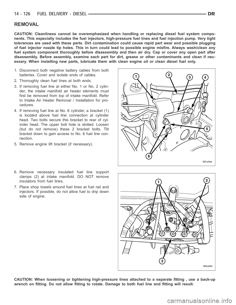
1. Disconnect both negative battery cables from both
batteries. Cover and isolate ends of cables.
2. Thoroughly clean fuel lines at both ends.
3. If removing fuel line at either No. 1 or No. 2 cylin-
der, the intake manifold air heater elements must
first be removed from top of intake manifold. Refer
to Intake Air Heater Removal / Installation for pro-
cedures.
4. If removing fuel line at No. 6 cylinder, a bracket (1)
is located above fuel line connection at cylinder
head. Two bolts secure this bracket to rear of cyl-
inder head. The upper bolt hole is slotted. Loosen
(but do not remove) these 2 bracket bolts. Tilt
bracket down to gain access to No. 6 fuel line con-
nection.
5. Remove engine lift bracket (if necessary).
6. Remove necessary insulated fuel line support
clamps (2) at intake manifold. DO NOT remove
insulators from fuel lines.
7. Place shop towels around fuel lines at fuel rail and
injectors. If possible, do not allow fuel to drip down
side of engine.
CAUTION: When loosening or tightening high-pressure lines attached to a separate fitting , use a back-up
wrench on fitting. Do not allow fitting to rotate. Damage to both fuel line and fitting will result.
Page 2367 of 5267
VALVE - FUEL PRESSURE LIMITING
DESCRIPTION
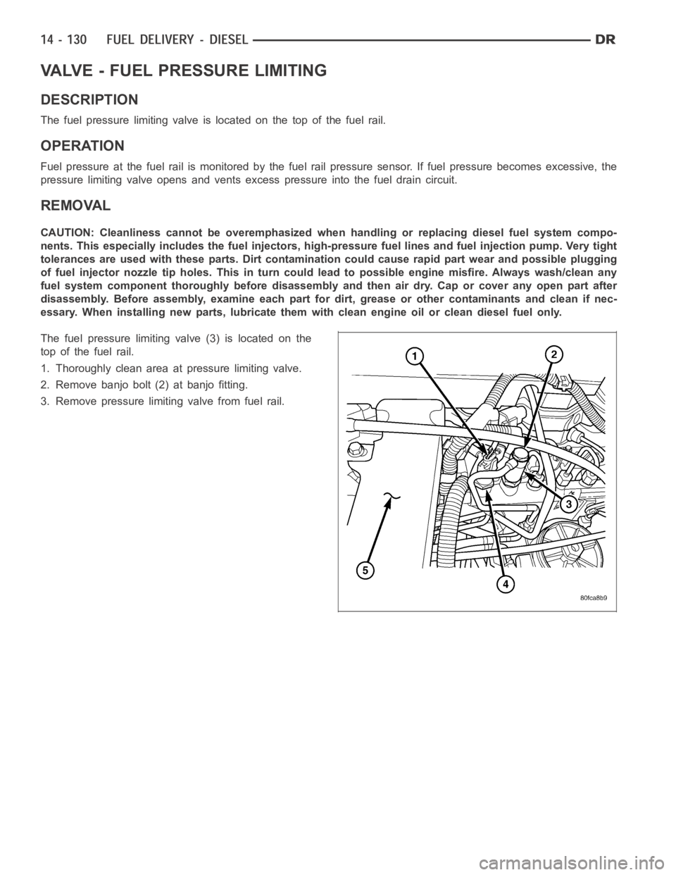
The fuel pressure limiting valve is located on the top of the fuel rail.
OPERATION
Fuel pressure at the fuel rail is monitored by the fuel rail pressure sensor. If fuel pressure becomes excessive, the
pressure limiting valve opens and vents excess pressure into the fuel draincircuit.
REMOVAL
CAUTION: Cleanliness cannot be overemphasized when handling or replacingdieselfuelsystemcompo-
nents. This especially includes the fuel injectors, high-pressure fuel lines and fuel injection pump. Very tight
tolerances are used with these parts. Dirt contamination could cause rapid part wear and possible plugging
of fuel injector nozzle tip holes. This in turn could lead to possible engine misfire. Always wash/clean any
fuel system component thoroughly before disassembly and then air dry. Capor cover any open part after
disassembly. Before assembly, examine each part for dirt, grease or othercontaminants and clean if nec-
essary. When installing new parts, lubricate them with clean engine oil orclean diesel fuel only.
The fuel pressure limiting valve (3) is located on the
top of the fuel rail.
1. Thoroughly clean area at pressure limiting valve.
2. Remove banjo bolt (2) at banjo fitting.
3. Remove pressure limiting valve from fuel rail.