fuel DODGE RAM SRT-10 2006 Service Repair Manual
[x] Cancel search | Manufacturer: DODGE, Model Year: 2006, Model line: RAM SRT-10, Model: DODGE RAM SRT-10 2006Pages: 5267, PDF Size: 68.7 MB
Page 38 of 5267
When Monitored:
With the ignition on. Battery voltage greater than 10 volts.
Set Condition:
A shorted condition is detected in the ASD control circuit. One Trip Fault.Three good trips to turn off the MIL.
Possible Causes
(K342) ASD CONTROL OUTPUT CIRCUIT SHORTED TO GROUND
FUEL INJECTOR
IGNITION COIL
PCM
TIPM
Always perform the Pre-Diagnostic Troubleshooting procedure before proceeding. (Refer to 9 - ENGINE -
DIAGNOSIS AND TESTING).
Diagnostic Test
1.ASD OPERATION
Ignition on, engine not running.
With a scan tool under the ECM Actuators, actuate the ASD Circuit.
Are the Injectors actuating?
Ye s>>
Refer to the INTERMITTENT CONDITION Diagnostic Procedure.
Perform the POWERTRAIN VERIFICATION TEST. (Refer to 9 - ENGINE - STANDARD PROCEDURE)
No>>
Go To 2
2.ASD OPERATION FROM THE ECM
Turn the ignition off.
Disconnect the C2 TIPM harness connector.
Ignition on, engine not running.
Using the scan tool under the ECM Actuators, actuate the ASD Circuit.
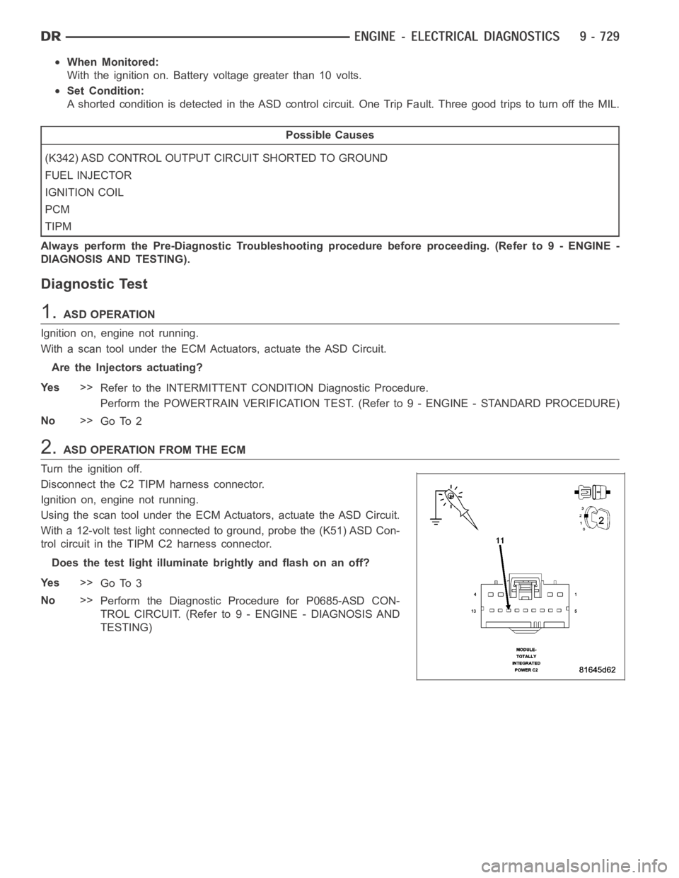
With a 12-volt test light connected to ground, probe the (K51) ASD Con-
trol circuit in the TIPM C2 harness connector.
Does the test light illuminate brightly and flash on an off?
Ye s>>
Go To 3
No>>
Perform the Diagnostic Procedure for P0685-ASD CON-
TROL CIRCUIT. (Refer to 9 - ENGINE - DIAGNOSIS AND
TESTING)
Page 39 of 5267
3.(K342) ASD CONTROL OUTPUT CIRCUIT SHORTED TO GROUND
Turn the ignition off
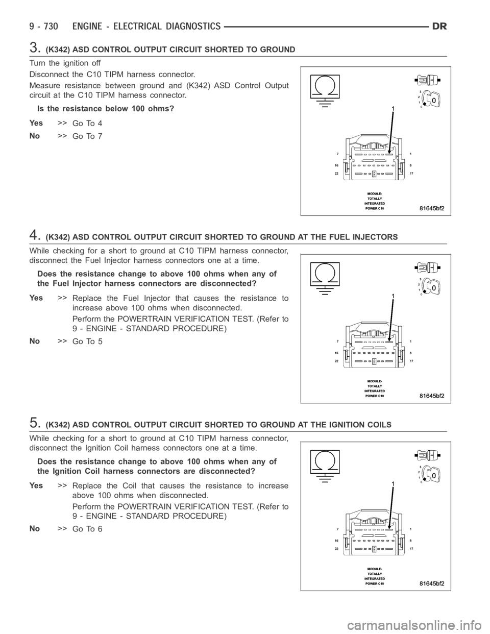
Disconnect the C10 TIPM harness connector.
Measure resistance between ground and (K342) ASD Control Output
circuit at the C10 TIPM harness connector.
Istheresistancebelow100ohms?
Ye s>>
Go To 4
No>>
Go To 7
4.(K342) ASD CONTROL OUTPUT CIRCUIT SHORTED TO GROUND AT THE FUEL INJECTORS
While checking for a short to ground at C10 TIPM harness connector,
disconnect the Fuel Injector harness connectors one at a time.
Does the resistance change to above 100 ohms when any of
the Fuel Injector harness connectors are disconnected?
Ye s>>
Replace the Fuel Injector that causes the resistance to
increase above 100 ohms when disconnected.
Perform the POWERTRAIN VERIFICATION TEST. (Refer to
9 - ENGINE - STANDARD PROCEDURE)
No>>
Go To 5
5.(K342) ASD CONTROL OUTPUT CIRCUIT SHORTED TO GROUND AT THE IGNITION COILS
While checking for a short to ground at C10 TIPM harness connector,
disconnect the Ignition Coil harness connectors one at a time.
Does the resistance change to above 100 ohms when any of
the Ignition Coil harness connectors are disconnected?
Ye s>>
Replace the Coil that causes the resistance to increase
above 100 ohms when disconnected.
Perform the POWERTRAIN VERIFICATION TEST. (Refer to
9 - ENGINE - STANDARD PROCEDURE)
No>>
Go To 6
Page 42 of 5267
When Monitored:
With the ignition on. Battery voltage greater than 10 volts.
Set Condition:
A shorted condition is detected in the ASD control circuit. One Trip Fault.Three good trips to turn off the MIL.
Possible Causes
(K342) ASD CONTROL OUTPUT CIRCUIT SHORTED TO VOLTAGE
FUEL INJECTOR
IGNITION COIL
ECM
TIPM
Always perform the Pre-Diagnostic Troubleshooting procedure before proceeding. (Refer to 9 - ENGINE -
DIAGNOSIS AND TESTING).
Diagnostic Test
1.ACTIVE DTC
Ignition on, engine not running.
With a scan tool, read DTCs.
Is the DTC active at this time?
Ye s>>
Go To 2
No>>
Refer to the INTERMITTENT CONDITION Diagnostic Procedure.
Perform the POWERTRAIN VERIFICATION TEST. (Refer to 9 - ENGINE - STANDARD PROCEDURE)
2.ASD OPERATION FROM THE ECM
Turn the ignition off.
Disconnect the C2 TIPM harness connector.
Ignition on, engine not running.
Using the scan tool under the ECM Actuators, actuate the ASD Circuit.
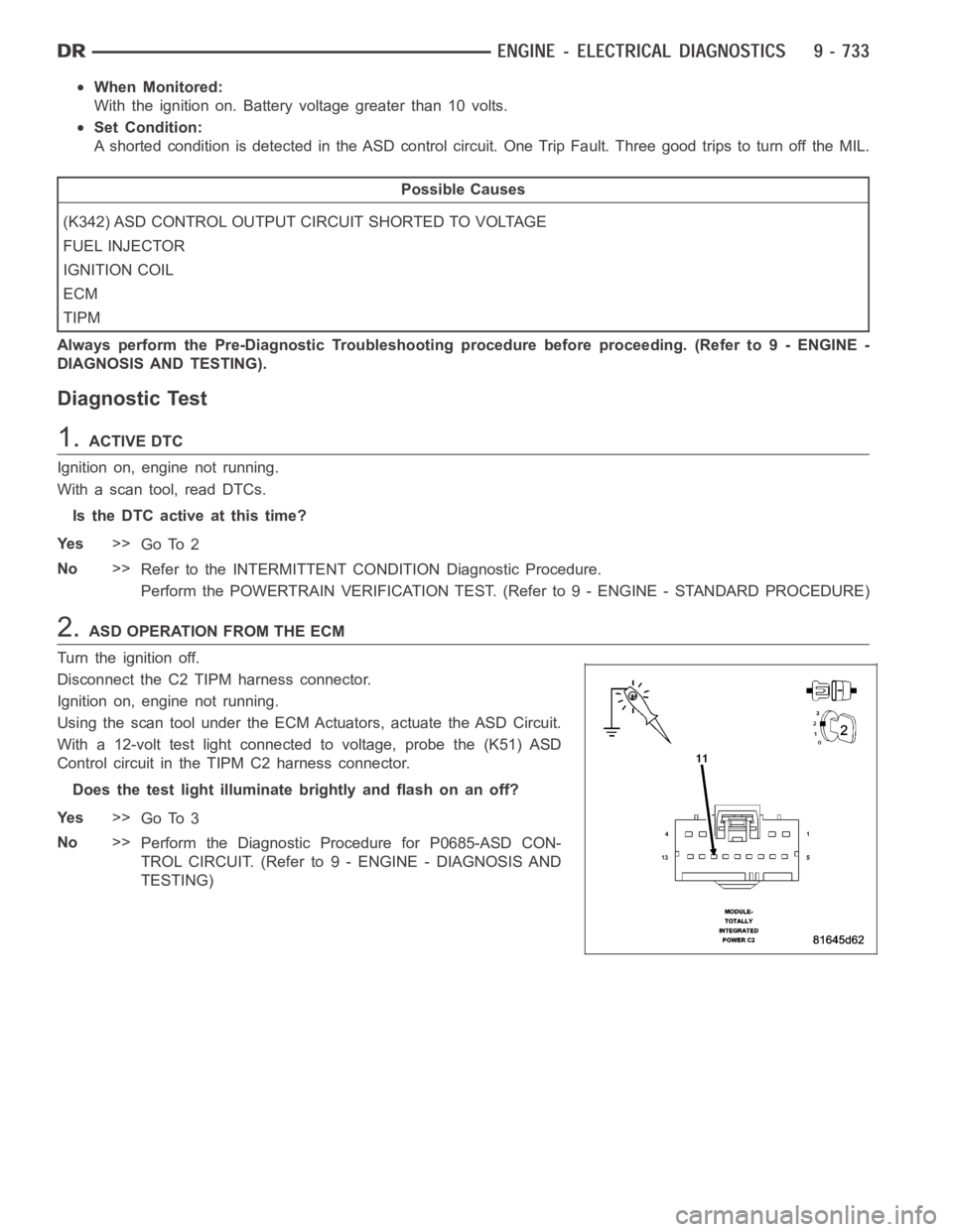
With a 12-volt test light connected to voltage, probe the (K51) ASD
Control circuit in the TIPM C2 harness connector.
Does the test light illuminate brightly and flash on an off?
Ye s>>
Go To 3
No>>
Perform the Diagnostic Procedure for P0685-ASD CON-
TROL CIRCUIT. (Refer to 9 - ENGINE - DIAGNOSIS AND
TESTING)
Page 43 of 5267
3.(K342) ASD CONTROL OUTPUT CIRCUIT SHORTED TO VOLTAGE
Turn the ignition off
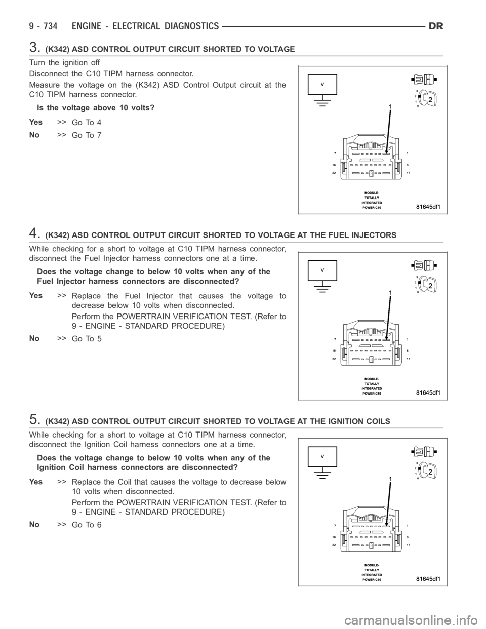
Disconnect the C10 TIPM harness connector.
Measure the voltage on the (K342) ASD Control Output circuit at the
C10 TIPM harness connector.
Is the voltage above 10 volts?
Ye s>>
Go To 4
No>>
Go To 7
4.(K342) ASD CONTROL OUTPUT CIRCUIT SHORTED TO VOLTAGE AT THE FUEL INJECTORS
While checking for a short to voltage at C10 TIPM harness connector,
disconnect the Fuel Injector harness connectors one at a time.
Does the voltage change to below 10 volts when any of the
Fuel Injector harness connectors are disconnected?
Ye s>>
Replace the Fuel Injector that causes the voltage to
decrease below 10 volts when disconnected.
Perform the POWERTRAIN VERIFICATION TEST. (Refer to
9 - ENGINE - STANDARD PROCEDURE)
No>>
Go To 5
5.(K342) ASD CONTROL OUTPUT CIRCUIT SHORTED TO VOLTAGE AT THE IGNITION COILS
While checking for a short to voltage at C10 TIPM harness connector,
disconnect the Ignition Coil harness connectors one at a time.
Does the voltage change to below 10 volts when any of the
Ignition Coil harness connectors are disconnected?
Ye s>>
Replace the Coil that causes the voltage to decrease below
10 volts when disconnected.
Perform the POWERTRAIN VERIFICATION TEST. (Refer to
9 - ENGINE - STANDARD PROCEDURE)
No>>
Go To 6
Page 46 of 5267
When Monitored:
With the ignition on. Battery voltage greater than 10 volts.
Set Condition:
An open condition is detected in the ASD control circuit. One Trip Fault. Three good trips to turn off the MIL.
Possible Causes
(K342) ASD CONTROL OUTPUT CIRCUIT OPEN
FUEL INJECTOR
IGNITION COIL
PCM
TIPM
Always perform the Pre-Diagnostic Troubleshooting procedure before proceeding. (Refer to 9 - ENGINE -
DIAGNOSIS AND TESTING).
Diagnostic Test
1.ACTIVE DTC
Ignition on, engine not running.
With a scan tool, read DTCs.
Is the DTC active at this time?
Ye s>>
Go To 2
No>>
Refer to the INTERMITTENT CONDITION Diagnostic Procedure.
Perform the POWERTRAIN VERIFICATION TEST. (Refer to 9 - ENGINE - STANDARD PROCEDURE)
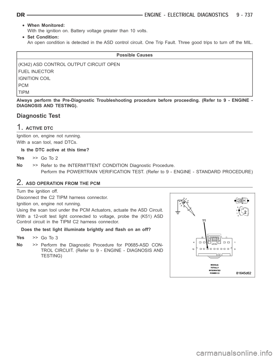
2.ASD OPERATION FROM THE PCM
Turn the ignition off.
Disconnect the C2 TIPM harness connector.
Ignition on, engine not running.
Using the scan tool under the PCM Actuators, actuate the ASD Circuit.
With a 12-volt test light connected to voltage, probe the (K51) ASD
Control circuit in the TIPM C2 harness connector.
Does the test light illuminate brightly and flash on an off?
Ye s>>
Go To 3
No>>
Perform the Diagnostic Procedure for P0685-ASD CON-
TROL CIRCUIT. (Refer to 9 - ENGINE - DIAGNOSIS AND
TESTING)
Page 47 of 5267
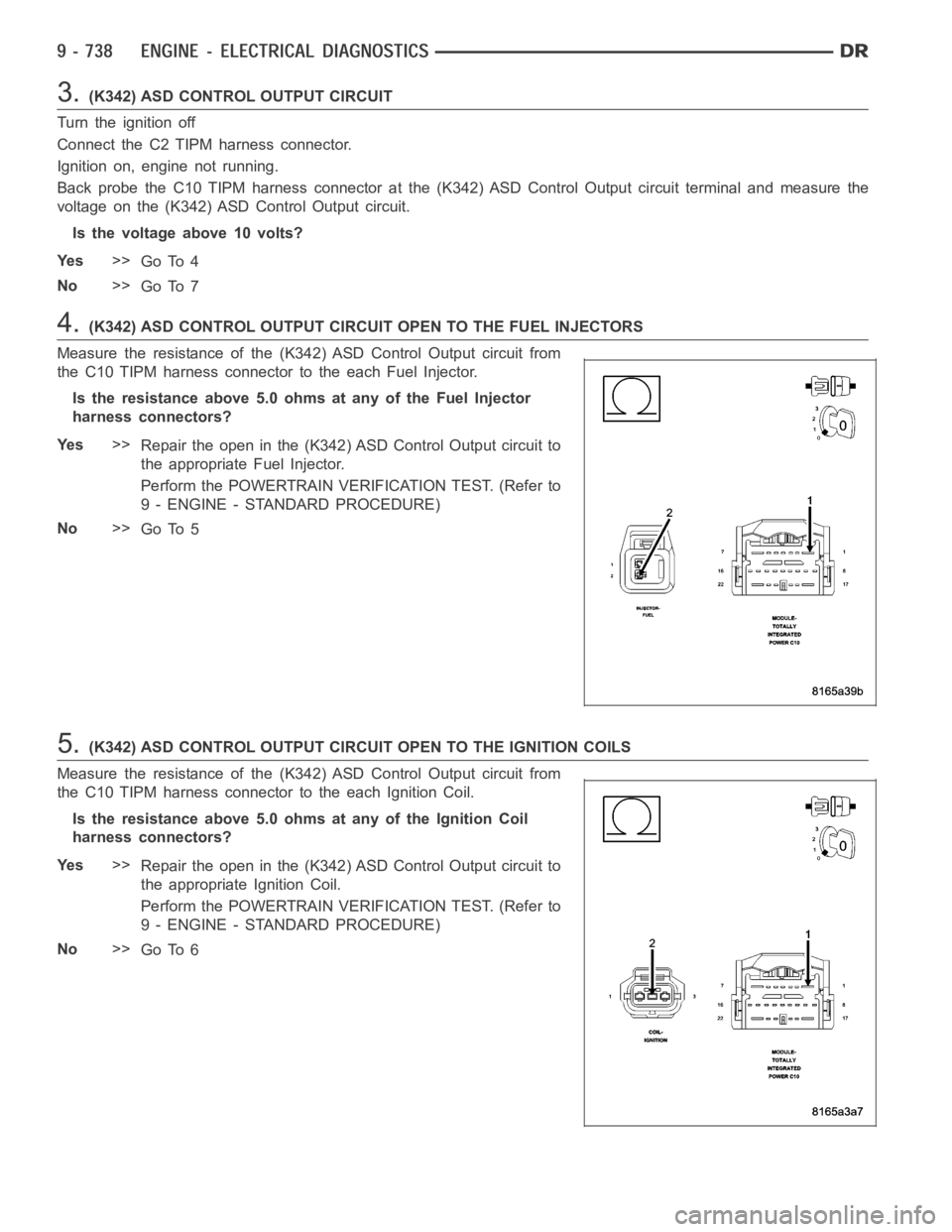
3.(K342) ASD CONTROL OUTPUT CIRCUIT
Turn the ignition off
Connect the C2 TIPM harness connector.
Ignition on, engine not running.
Back probe the C10 TIPM harness connector at the (K342) ASD Control Output circuit terminal and measure the
voltage on the (K342) ASD Control Output circuit.
Is the voltage above 10 volts?
Ye s>>
Go To 4
No>>
Go To 7
4.(K342) ASD CONTROL OUTPUT CIRCUIT OPEN TO THE FUEL INJECTORS
Measure the resistance of the (K342) ASD Control Output circuit from
the C10 TIPM harness connector to the each Fuel Injector.
Is the resistance above 5.0 ohms at any of the Fuel Injector
harness connectors?
Ye s>>
Repair the open in the (K342) ASD Control Output circuit to
the appropriate Fuel Injector.
Perform the POWERTRAIN VERIFICATION TEST. (Refer to
9 - ENGINE - STANDARD PROCEDURE)
No>>
Go To 5
5.(K342) ASD CONTROL OUTPUT CIRCUIT OPEN TO THE IGNITION COILS
Measure the resistance of the (K342) ASD Control Output circuit from
the C10 TIPM harness connector to the each Ignition Coil.
Is the resistance above 5.0 ohms at any of the Ignition Coil
harness connectors?
Ye s>>
Repair the open in the (K342) ASD Control Output circuit to
the appropriate Ignition Coil.
Perform the POWERTRAIN VERIFICATION TEST. (Refer to
9 - ENGINE - STANDARD PROCEDURE)
No>>
Go To 6
Page 50 of 5267
When Monitored:
With the ignition on. Battery voltage greater than 10 volts.
Set Condition:
An overcurrent condition is detected in the ASD control circuit. One Trip Fault. Three good trips to turn off the
MIL.
Possible Causes
(K342) ASD CONTROL OUTPUT CIRCUIT EXCESSIVE RESISTANCE
FUEL INJECTOR
IGNITION COIL
PCM
TIPM
Always perform the Pre-Diagnostic Troubleshooting procedure before proceeding. (Refer to 9 - ENGINE -
DIAGNOSIS AND TESTING).
Diagnostic Test
1.ACTIVE DTC
Ignition on, engine not running.
With a scan tool, read DTCs.
Is the DTC active at this time?
Ye s>>
Go To 2
No>>
Refer to the INTERMITTENT CONDITION Diagnostic Procedure.
Perform the POWERTRAIN VERIFICATION TEST. (Refer to 9 - ENGINE - STANDARD PROCEDURE)
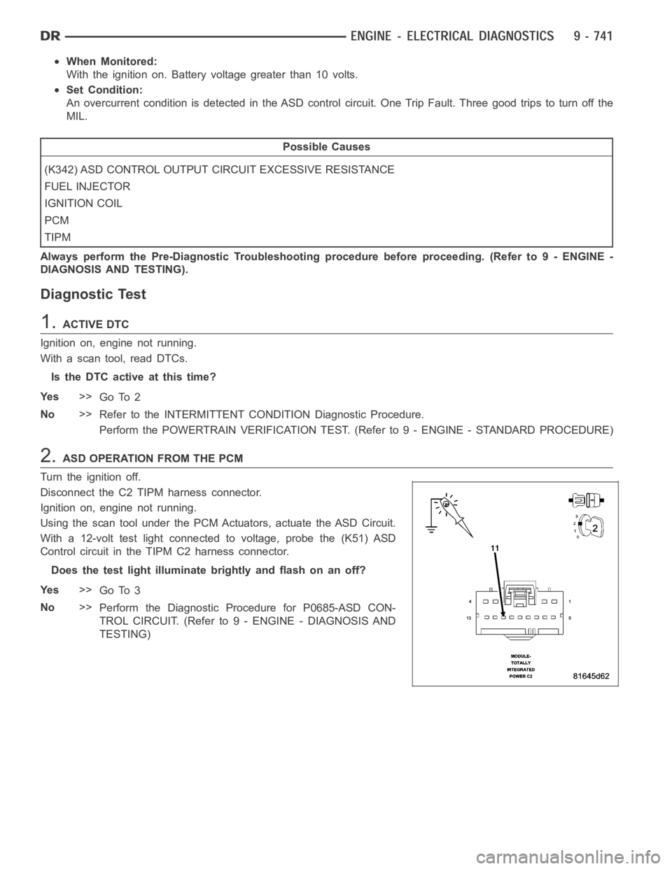
2.ASD OPERATION FROM THE PCM
Turn the ignition off.
Disconnect the C2 TIPM harness connector.
Ignition on, engine not running.
Using the scan tool under the PCM Actuators, actuate the ASD Circuit.
With a 12-volt test light connected to voltage, probe the (K51) ASD
Control circuit in the TIPM C2 harness connector.
Does the test light illuminate brightly and flash on an off?
Ye s>>
Go To 3
No>>
Perform the Diagnostic Procedure for P0685-ASD CON-
TROL CIRCUIT. (Refer to 9 - ENGINE - DIAGNOSIS AND
TESTING)
Page 51 of 5267
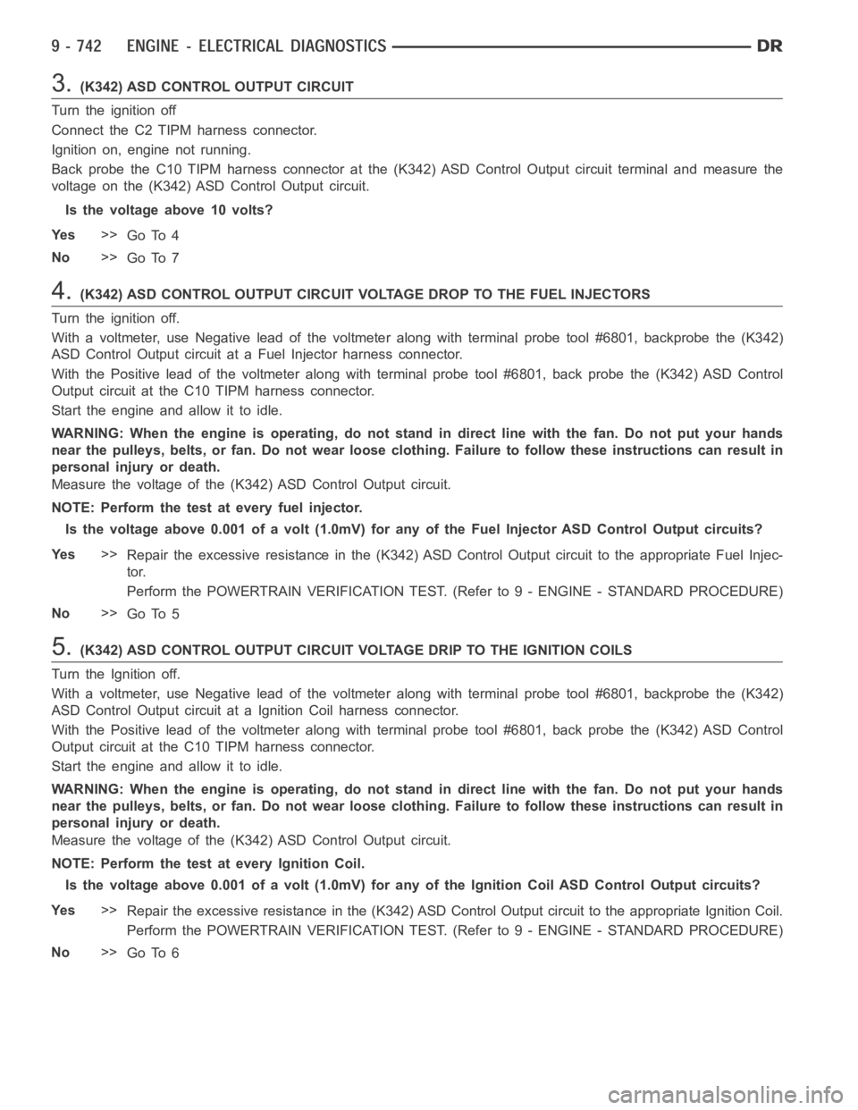
3.(K342) ASD CONTROL OUTPUT CIRCUIT
Turn the ignition off
Connect the C2 TIPM harness connector.
Ignition on, engine not running.
Back probe the C10 TIPM harness connector at the (K342) ASD Control Output circuit terminal and measure the
voltage on the (K342) ASD Control Output circuit.
Is the voltage above 10 volts?
Ye s>>
Go To 4
No>>
Go To 7
4.(K342) ASD CONTROL OUTPUT CIRCUIT VOLTAGE DROP TO THE FUEL INJECTORS
Turn the ignition off.
With a voltmeter, use Negative lead of the voltmeter along with terminal probe tool #6801, backprobe the (K342)
ASD Control Output circuit at a Fuel Injector harness connector.
With the Positive lead of the voltmeter along with terminal probe tool #6801, back probe the (K342) ASD Control
Output circuit at the C10 TIPM harness connector.
Start the engine and allow it to idle.
WARNING: When the engine is operating, do not stand in direct line with the fan. Do not put your hands
near the pulleys, belts, or fan. Do notwear loose clothing. Failure to follow these instructions can result in
personal injury or death.
Measure the voltage of the (K342) ASD Control Output circuit.
NOTE: Perform the test at every fuel injector.
Is the voltage above 0.001 of a volt (1.0mV) for any of the Fuel Injector ASD Control Output circuits?
Ye s>>
Repair the excessive resistance in the (K342) ASD Control Output circuit to the appropriate Fuel Injec-
tor.
Perform the POWERTRAIN VERIFICATION TEST. (Refer to 9 - ENGINE - STANDARD PROCEDURE)
No>>
Go To 5
5.(K342) ASD CONTROL OUTPUT CIRCUIT VOLTAGE DRIP TO THE IGNITION COILS
Turn the Ignition off.
With a voltmeter, use Negative lead of the voltmeter along with terminal probe tool #6801, backprobe the (K342)
ASD Control Output circuit at a Ignition Coil harness connector.
With the Positive lead of the voltmeter along with terminal probe tool #6801, back probe the (K342) ASD Control
Output circuit at the C10 TIPM harness connector.
Start the engine and allow it to idle.
WARNING: When the engine is operating, do not stand in direct line with the fan. Do not put your hands
near the pulleys, belts, or fan. Do notwear loose clothing. Failure to follow these instructions can result in
personal injury or death.
Measure the voltage of the (K342) ASD Control Output circuit.
NOTE: Perform the test at every Ignition Coil.
Is the voltage above 0.001 of a volt (1.0mV) for any of the Ignition Coil ASD Control Output circuits?
Ye s>>
Repair the excessive resistance in the (K342) ASD Control Output circuit to the appropriate Ignition Coil.
Perform the POWERTRAIN VERIFICATION TEST. (Refer to 9 - ENGINE - STANDARD PROCEDURE)
No>>
Go To 6
Page 79 of 5267

P127C-FUEL PUMP CONTROL CIRCUIT 2 LOW
For a complete wiring diagramRefer to Section 8W.
Page 80 of 5267

When Monitored:
With the ignition on. Battery voltage greater than 10.4 volts.
Set Condition:
A shorted low condition in the Fuel Pump Control circuit has been detected by the TIPM. One Trip Fault. Three
good trips to turn off the MIL.
Possible Causes
(K31) FUEL PUMP CONTROL CIRCUIT SHORTED TO GROUND
FUEL PUMP
TIPM
Always perform the Pre-Diagnostic Troubleshooting procedure before proceeding. (Refer to 9 - ENGINE -
DIAGNOSIS AND TESTING).
Diagnostic Test
1.FUEL PUMP OPERATION
Ignition on, engine not running.
With a scan tool under the PCM Actuators, actuate the Fuel Pump.
Is the Fuel Pump operating?
Ye s>>
Refer to the INTERMITTENT CONDITION Diagnostic Procedure.
Perform the POWERTRAIN VERIFICATION TEST. (Refer to 9 - ENGINE - STANDARD PROCEDURE)
No>>
Go To 2
2.FUEL PUMP CONTROL OPERATION FROM THE PCM
Turn the ignition off.
Disconnect the C1 TIPM harness connector.
Ignition on, engine not running.
Using the scan tool under the PCM Actuators, actuate the Fuel Pump.
With a 12-volt test light connected to ground, probe the (K31) Fuel
Pump Control circuit in the TIPM C1 harness connector.
Does the test light illuminate brightly and flash on an off?
Ye s>>
Go To 3
No>>
Perform the Diagnostic Procedure for P0627-FUEL PUMP
CONTROL CIRCUIT. (Refer to 9 - ENGINE - DIAGNOSIS
AND TESTING)