power steering DODGE STRATUS COUPE 2005 2.G Owners Manual
[x] Cancel search | Manufacturer: DODGE, Model Year: 2005, Model line: STRATUS COUPE, Model: DODGE STRATUS COUPE 2005 2.GPages: 396
Page 144 of 396
NGear positions........................158
NDriving speed
(Vehicles with automatic transaxle).........159
NHolding on an upgrade.................159
NTransaxle reset mode...................160
mAutomatic transaxle Autostick
(if so equipped)
........................160
NSelector lever operation.................161
NIndicator lights.......................163
NSelector positions (Main gate).............164
NSelector positions Manual gate Autostick.....165
NHolding on an upgrade.................167
NTransaxle reset mode...................168
mManual transaxle (if so equipped)..........168
NTo start.............................169
NProper shift points.....................169NRecommended downshifting speed.........171
NDriving precautions....................171
mParking brake.........................171
mBrake pedal...........................173
mPower brakes.........................174
mBrake pad wear alarm...................174
mAnti-lock braking (ABS) system
(if so equipped)
........................175
NGeneral driving hints
(standard/anti-lock brakes)...............175
mSteering wheel tilt lock lever..............177
mPower steering........................178
mInside Day/Night rearview mirrors.........179
NElectrochromic inside rearview mirror
(if so equipped.......................180
NElectrochromic mirror operation
(if so equipped).......................181
144 STARTING AND DRIVING
Page 152 of 396

NOTE: For vehicles with an automatic transaxle, the key
cannot be removed unless the selector lever is set to the
ªPº (PARK) position.
ACC
Allows operation of electrical accessories with the engine
off.
START
Engages the starter. After the engine starts, release the
key and it will return automatically to the ªONº position.
ON
The engine runs and all accessories can be used.
NOTE:Do not use the ªONº position to operate acces-
sories.
CAUTION!
²Do not remove the ignition key from the ignition
switch while driving. The steering wheel will
lock, causing loss of control.
²If the engine is turned off while driving, the
power brake servomechanism will cease to func-
tion and braking efficiency will deteriorate. Also,
the power steering system will not function and it
will require greater effort to operate the steering.
²Do not leave the key in the ªONº position for a
long time when the engine is not running; doing
so will cause the battery to discharge.
²Do not turn the key to the ªSTARTº position
when the engine is running; doing so could dam-
age the starter motor.
KEY REMINDER CHIME
If the driver's door is opened while the ignition key is in
the ªLOCKº or ªACCº position, a warning chime
sounds.
152 STARTING AND DRIVING
Page 178 of 396

WARNING!
²After adjustment, to the desired height, check to
be sure that the lever is locked.
²Do not attempt to adjust the steering wheel while
driving. This can be dangerous.
POWER STEERING
Your vehicle is equipped with power assisted steering as
standard equipment. The power assisted steering system
of your vehicle provides mechanical steering capability
in the event power assist is lost.
If for some reason the hydraulic pressure is interrupted,
it will still be possible to steer your vehicle. Under these
conditions you will observe a substantial increase in
steering effort. Should loss of hydraulic pressure occur
take your vehicle to an authorized dealer.
WARNING!
Never turn off the engine while the vehicle is
moving. Your ability to control the vehicle may be
seriously reduced.
CAUTION!
Do not leave the steering wheel in the fully turned
position. This can cause the power steering pump to
be damaged due to poor lubrication.
178 STARTING AND DRIVING
Page 263 of 396
IF THE VEHICLE BREAKS DOWN
If the vehicle breaks down on the road, move to the
shoulder and activate the hazard warning flashers. If
there is no shoulder, or the shoulder is not safe, drive in
the right lane, slowly, with the hazard flashers activated,
until you reach a safe place to stop. Keep the flashers
activated.
If the engine quits
If the engine stops, power will be lost to the steering and
brakes, making steering and braking difficult.
1. The brake booster becomes inoperative and the brake
pedal will be harder to push than usual.
2. Since power steering system is not operative, the
steering wheel will be stiff when turning. Turn the wheel
with more effort than usual.
OPERATION UNDER ADVERSE DRIVING
CONDITIONS
If your vehicle becomes stuck in sand, mud or
snow
If the vehicle becomes stuck in snow, sand, or mud, it can
often be moved by a rocking motion. Turn your steering
wheel right and left to clear the area around the wheels.
Move the gearshift lever or selector lever rhythmically
between the 1st and REVERSE position (with manual
transaxle), ``L'' (Low) and ``R'' (REVERSE) position (with
automatic transaxle), Autostick and ``R'' (REVERSE posi-
tion (with automatic transaxle autostick), while applying
slight pressure to the accelerator pedal.
Avoid racing the engine or spinning the wheels. Pro-
longed efforts to free a stuck vehicle may result in
overheating and transaxle failure.
Allow the engine to idle for a few minutes to let the
transaxle cool between rocking attempts.
If the vehicle remains stuck after several rocking at-
tempts, seek other assistance.
EMERGENCIES 263
8
Page 285 of 396
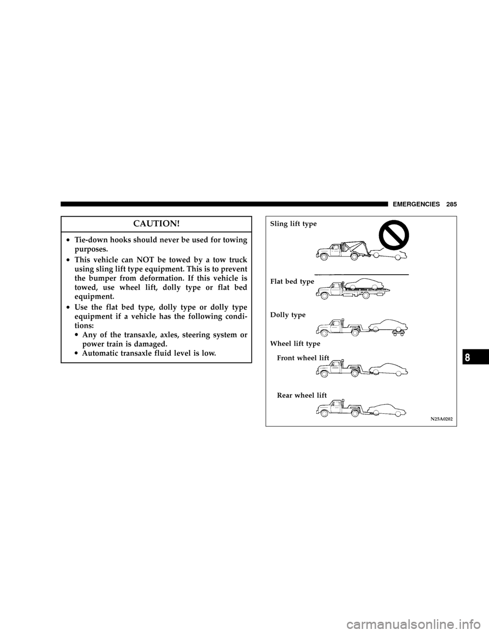
CAUTION!
²Tie-down hooks should never be used for towing
purposes.
²This vehicle can NOT be towed by a tow truck
using sling lift type equipment. This is to prevent
the bumper from deformation. If this vehicle is
towed, use wheel lift, dolly type or flat bed
equipment.
²Use the flat bed type, dolly type or dolly type
equipment if a vehicle has the following condi-
tions:
·Any of the transaxle, axles, steering system or
power train is damaged.
·Automatic transaxle fluid level is low.
N25A0202
Sling lift type
Flat bed type
Dolly type
Wheel lift type
Front wheel lift
Rear wheel lift
EMERGENCIES 285
8
Page 310 of 396
NDisconnection and connection.............327
mAutomatic transaxle.....................329
NTo check the fluid level..................330
NProcedure for checking the fluid level.......330
mManual transaxle.......................331
mDisc brake pads, rear drum brake linings
and rear wheel cylinders.................331
mBrake hoses...........................331
mBall joint, steering linkage seal and drive
shaft boots...........................331
mSupplemental Restraint System (SRS)........331
mHood lock release mechanism and
safety catch
...........................332
mExhaust system........................332
mWindshield wiper blades.................333
NWindshield washers....................333
mParking brake.........................334
mDrive belt (for generator, water pump, power
steering pump)
........................335
mTiming belt...........................336
mTi re s................................336
NTire inflation pressures..................340
NRadial ply tires.......................341
N
Tire pressure for sustained high-speed driving...342
NReplacing tire and wheels................342
NTire maintenance......................342
NCargo loads..........................346
NTread wear indicators...................346
NTire rotation.........................347
NTire chains...........................348
NSnow tires...........................348
mRegular Maintenance Schedule.............349
mSevere Maintenance Schedule..............357
310 MAINTENANCE
Page 311 of 396
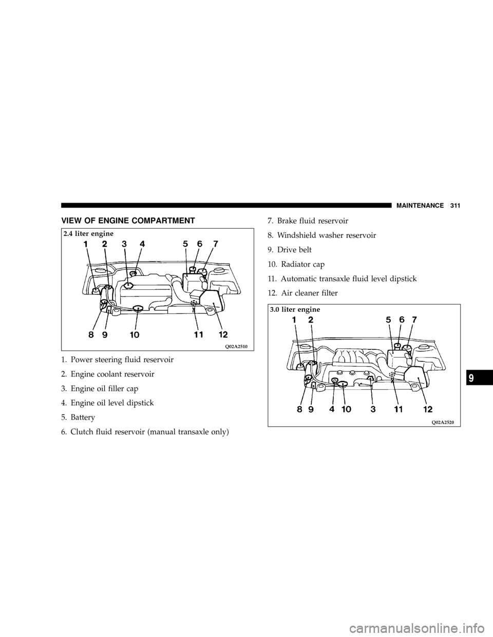
VIEW OF ENGINE COMPARTMENT
1. Power steering fluid reservoir
2. Engine coolant reservoir
3. Engine oil filler cap
4. Engine oil level dipstick
5. Battery
6. Clutch fluid reservoir (manual transaxle only)7. Brake fluid reservoir
8. Windshield washer reservoir
9. Drive belt
10. Radiator cap
11. Automatic transaxle fluid level dipstick
12. Air cleaner filter
Q02A2510
2.4 liter engine
Q02A2520
3.0 liter engine
MAINTENANCE 311
9
Page 335 of 396
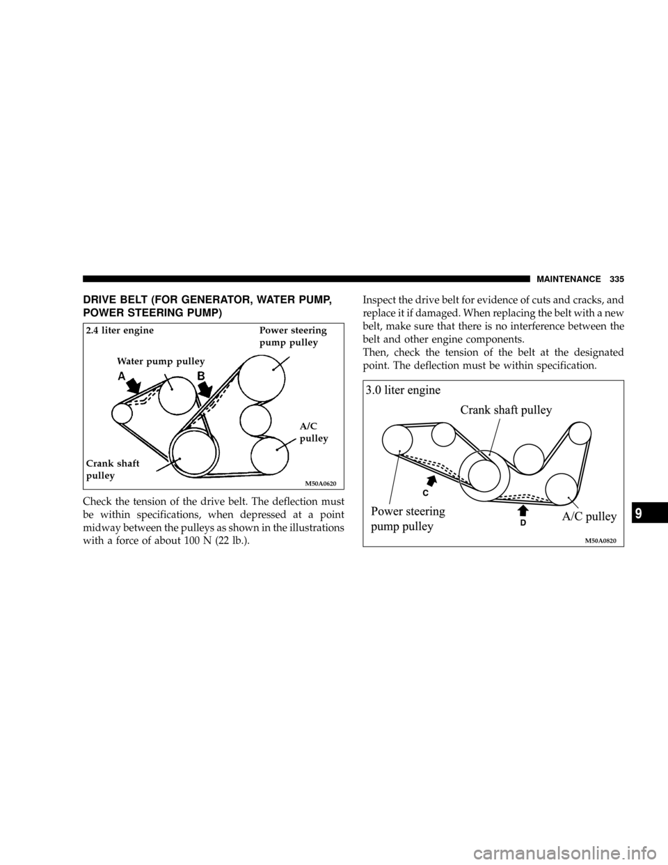
DRIVE BELT (FOR GENERATOR, WATER PUMP,
POWER STEERING PUMP)
Check the tension of the drive belt. The deflection must
be within specifications, when depressed at a point
midway between the pulleys as shown in the illustrations
with a force of about 100 N (22 lb.).Inspect the drive belt for evidence of cuts and cracks, and
replace it if damaged. When replacing the belt with a new
belt, make sure that there is no interference between the
belt and other engine components.
Then, check the tension of the belt at the designated
point. The deflection must be within specification.
M50A0620
Water pump pulley
Crank shaft
pulleyPower steering
pump pulley
A/C
pulley 2.4 liter engine
M50A0820
MAINTENANCE 335
9
Page 343 of 396
²Vehicle normal load on the tire : load on an individual
tire that is determined by distributing to each axle its
share of the curb weight, accessory weight, and nor-
mal occupant weight and dividing by two.
²Maximum loaded vehicle weight : the sum of ±
(a) Curb weight;
(b) Accessory weight:
(c) Vehicle capacity weight; and
(d) Production options weight.
²Curb weight : the weight of a motor vehicle with
standard equipment including the maximum capacity
of fuel, oil, and coolant, and, if so equipped, air
conditioning and additional weight optional engine.
²Accessory weight : the combined weight (in excess of
those standard items which may be replaced) of auto-
matic transmission, power steering, power brakes,
power windows, power seats, radio, and heater, to the
extent that these items are available as factory-
installed equipment (whether installed or not).
²Vehicle capacity weight : the rated cargo and luggage
load plus 150 lbs (68kg) times the vehicle's designated
seating capacity.
²Production options weight : the combined weight of
those installed regular production options weighing
over 5 lbs (2.3kg) in excess of those standard items
which they replace, not previously considered in curb
weight or accessory weight, including heavy duty
brakes, ride levelers, roof rack, heavy duty battery, and
special trim.
²Normal occupant weight : 150 lbs (68kg) times the
number of specified occupants. (In your vehicle the
number is 3).
²Occupant distribution : distribution of occupants in a
vehicle as specified. (In your vehicle the distribution is
2 in front, 1 in second seat).
Steps for Determining Correct Load Limit
1. Locate the statement9The combined weight of occu-
pants and cargo should never exceed XXX pounds9on
your vehicle's placard.
MAINTENANCE 343
9
Page 350 of 396
!24,000 Miles (38 000 km) or at 24 months
NCheck automatic transaxle fluid level.
NInspect disc brake pads, rotors and calipers for
wear and leaks.
NCheck brake hoses for deterioration or leaks.
NInspect drive shaft boots for grease leaks and
damage.
NChange engine oil and engine oil filter.
NRotate tires.
MILEAGE/
MONTHSDEALERSHIP
NAME/CODE DATEREPAIR
ORDER #
!30,000 Miles (48 000 km) or at 30 months
NReplace air cleaner filter.
NReplace spark plugs, standard type.
NCheck drive belts condition (for the generator,
water pump, power steering pump).
NCheck manual transaxle oil level.
NCheck coolant hoses (radiator hose, heater hose).
NCheck fuel hoses condition.
NInspect rear drum brake linings and rear wheel
cylinders (except vehicles with disc brakes) for
wear and leaks of all wheels.
NInspect ball joint and steering linkage seals for
grease leaks and damage.
NInspect suspension system for looseness and dam-
age.
NCheck and service exhaust system as required
(connection portion of muffler, muffler pipes and
converter heat shields).
MILEAGE/
MONTHSDEALERSHIP
NAME/CODE DATEREPAIR
ORDER #
350 MAINTENANCE