weight DODGE STRATUS COUPE 2005 2.G Owners Manual
[x] Cancel search | Manufacturer: DODGE, Model Year: 2005, Model line: STRATUS COUPE, Model: DODGE STRATUS COUPE 2005 2.GPages: 396
Page 43 of 396
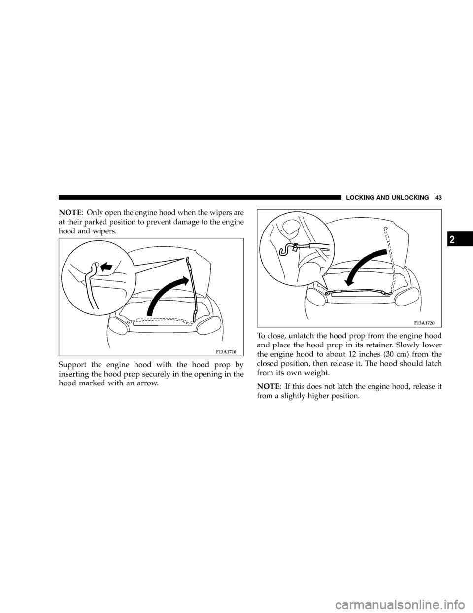
NOTE: Only open the engine hood when the wipers are
at their parked position to prevent damage to the engine
hood and wipers.
Support the engine hood with the hood prop by
inserting the hood prop securely in the opening in the
hood marked with an arrow.To close, unlatch the hood prop from the engine hood
and place the hood prop in its retainer. Slowly lower
the engine hood to about 12 inches (30 cm) from the
closed position, then release it. The hood should latch
from its own weight.
NOTE
: If this does not latch the engine hood, release it
from a slightly higher position.
F13A1710
F13A1720
LOCKING AND UNLOCKING 43
2
Page 76 of 396
WARNING!
²The extender should only be used if the existing
belt is not long enough.
Persons who can use the standard seat belt should
not use an extender. Unnecessary use could result
in serious personal injury in the event of a colli-
sion.
²When not required, the extender must be removed
and stowed because the use of the extender when
not required may deactivate the seat belt locking
mechanism.
CHILD RESTRAINTS
When transporting infants or small children in your
vehicle, an appropriate child restraint system should
always be used. This is required by law in most states.
Child restraints specifically designed for infants and
small children are offered by several manufacturers. Only
choose a child restraint system with a label certifying it
complies with Federal Motor Vehicle Safety Standard
213.The child restraint system should be appropriate for your
child's weight and height and properly fit the vehicle's
seat.
All children should be restrained in a restraint device that
offers the maximum protection for their size and age.
·Children less than 1 year and less than 20 pounds must
ride in a rear-facing child safety seat only in the rear
seat.
·Children older than 1 year who weigh less than 40
pounds or are less than 40 inches tall should be in a
forward-facing restraint in the rear seat.
·Children who weigh more than 40 pounds or are more
than 40 inches tall - regardless of age - should use a
booster seat in the rear seat until the lap/shoulder belt
fits properly.
76 SEATS, SEAT BELTS, CHILD RESTRAINTS AND AIR BAGS
Page 79 of 396
WARNING!
²It is important to use an approved rear facing
infant restraint until the infant is one year old to
allow the infant's neck and spine to develop
enough to support the weight of their head in the
event of a collision.
²When installing a child restraint system, follow
the instructions provided by the manufacturer
and follow the directions in this manual. Failure
to do so can result in severe or fatal injury to your
child in a collision or sudden stop.
²After installation, push and pull the child re-
straint system back and forth, and side to side, to
see that it is firmly secured. If the child restraint
system is not installed securely, it may cause
injury to the child or other occupants in the event
of a collision or sudden stop.
²When not in use, keep your child restraint system
secured with the seat belt or remove it from the
vehicle in order to prevent it from being thrown
inside the vehicle during an accident.
NOTE: Before purchasing a child restraint system, try
installing it in the rear seat to ensure a good fit. Due to the
location of the seat belt buckles and the shape of the seat
cushion it may be difficult to securely install some child
restraint systems.
If the child restraint system can be pulled forward or to
either side easily on the seat cushion after the seat belt
has been tightened, choose another child restraint sys-
tem.
²Depending on the seating position in the vehicle and
the child restraint system that you have, the child
restraint can be attached using one of the following 2
methods:
²To the lower anchorage in the rear seat ONLY if the
child restraint is compatible with the LATCH Sys-
tem. (See page 80).
²To the UNIBELT (See page 82).
SEATS, SEAT BELTS, CHILD RESTRAINTS AND AIR BAGS 79
3
Page 84 of 396

3. To activate the ALR mode, slowly pull the shoulder
part of the belt all the way out until it stops, then let the
belt feed back into the retractor.
4. After the belt has retracted, tug on it. If the belt is
locked, you will not be able to pull it out. If you can pull
the belt out, it is not locked and not in the ALR mode. You
will need to repeat steps 3 and 4.5. After confirming that the belt is locked, grab the
shoulder part of the belt near the buckle and pull up to
remove any slack from the lap part of the belt. Remem-
ber, if the lap part of the belt is not tight, the child
restraint system will not be secure. It may help to put
weight on the child restraint system and/or push on its
seatback while pulling up on the belt (see illustration).
G18C0550G18C0560
84 SEATS, SEAT BELTS, CHILD RESTRAINTS AND AIR BAGS
Page 146 of 396
BREAK-IN RECOMMENDATIONS
Advanced automobile manufacturing techniques permit
you to operate your new vehicle without experiencing a
long break-in period of low-speed driving.
However, you can add to the future performance and
economy of your vehicle by observing the following
precautions during the first 300 miles (500 km).
It is recommended that you drive your vehicle at mod-
erate speeds during the break-in period.
1. Avoid racing the engine.
2. Avoid harsh driving such as fast starts, sudden accel-
eration, prolonged high-speed driving and abrupt appli-
cation of the brakes. These operations not only have a
detrimental effect on the engine but also cause increased
fuel and oil consumption, which could result in malfunc-
tion of engine components. Be particularly careful to
avoid wide-open throttle acceleration in low gear.
3. Do not overload the vehicle. Observe the seating
capacity. (See ªWeightsº page 375)
4. Do not use this vehicle for trailer towing during the
break-in period.
FUEL SELECTION
Your vehicle is designed to use unleaded gasoline only. It
is equipped with a fuel filler tube especially designed to
accept only the smaller diameter unleaded gasoline dis-
pensing nozzle.
WARNING!
Gasoline is highly flammable and explosive. You can
be burned or seriously injured when handling it.
When refueling this vehicle, always turn the engine
off and keep flames, sparks, and smoking materials
away. Always handle fuel in well-ventilated outdoor
areas.
146 STARTING AND DRIVING
Page 206 of 396

Weight limits
Never exceed the maximum trailer weight (A), maximum
tongue weight (B), Gross Vehicle Weight Rating (GVWR)
and Gross Axle Weight Rating (GAWR).
I26A1290
206 STARTING AND DRIVING
Page 267 of 396
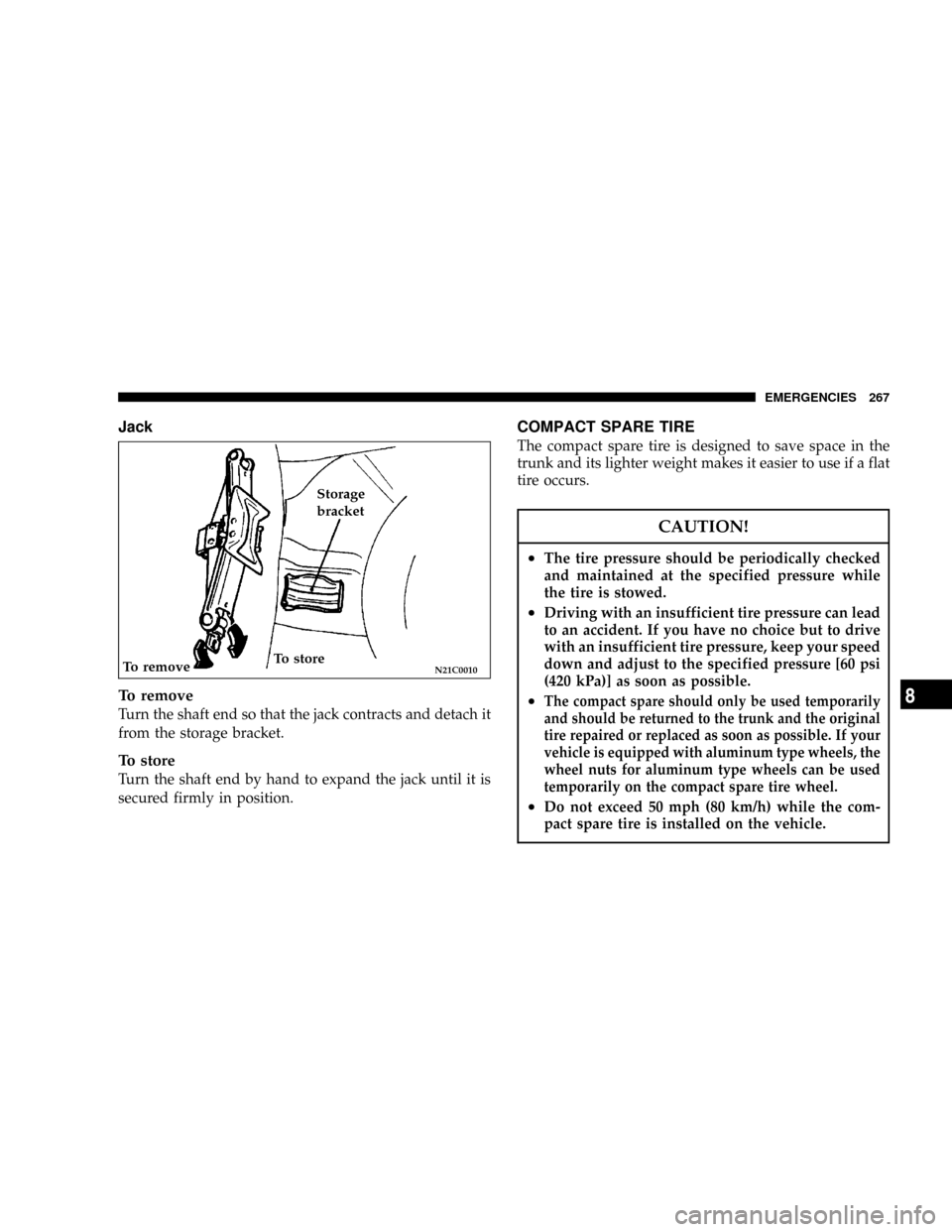
Jack
To remove
Turn the shaft end so that the jack contracts and detach it
from the storage bracket.
To store
Turn the shaft end by hand to expand the jack until it is
secured firmly in position.
COMPACT SPARE TIRE
The compact spare tire is designed to save space in the
trunk and its lighter weight makes it easier to use if a flat
tire occurs.
CAUTION!
²The tire pressure should be periodically checked
and maintained at the specified pressure while
the tire is stowed.
²Driving with an insufficient tire pressure can lead
to an accident. If you have no choice but to drive
with an insufficient tire pressure, keep your speed
down and adjust to the specified pressure [60 psi
(420 kPa)] as soon as possible.
²The compact spare should only be used temporarily
and should be returned to the trunk and the
original
tire repaired or replaced as soon as possible. If your
vehicle is equipped with aluminum type wheels, the
wheel nuts for aluminum type wheels can be used
temporarily on the compact spare tire wheel.
²Do not exceed 50 mph (80 km/h) while the com-
pact spare tire is installed on the vehicle.
N21C0010To removeTo storeStorage
bracket
EMERGENCIES 267
8
Page 341 of 396

one mile (1.6 km) after being stationary for three hours.
Cold inflation pressure must not exceed the maximum
values molded into the tire sidewall. After driving several
miles, tire inflation pressure may increase 2 to 6 psi (14 to 41
kPa) over the cold inflation pressure; do NOT let air out of
the tires to match the specified cold pressure, or your tires
will be underinflated.
Check your tires each time you refuel. If one tire looks lower
than the others, check the tire inflation pressure for all of
them. The following precautions also should be observed:
1. Keep your tires inflated to the pressures that are
recommended. (See the tire and loading information
placard attached the driver's side ``B''-Pillar.)
2. Stay within the load limits that are recommended.
3. Make sure that the weight of your vehicle load is
evenly distributed.
4. Drive at safe speeds.
5. After the tire inflation pressure has been adjusted,
check the tires for damage and air leaks. Be sure to
replace the rubber caps on the valve stems.
Radial ply tires
Radial ply tires provide improved tread life, road hazard
resistance and smoother high speed ride. The radial ply
factory-installed tires on this vehicle are of belted con-
struction and are selected to complement the ride and
handling characteristics of your vehicle.
Radial ply tires have the same load carrying capacity as
bias or bias-belted tires of the same letter size, and use the
same recommended inflation pressures.
Mixing of radial ply tires with bias or bias-belted tires is
not recommended. Combining radial ply and bias or
bias-belted tires on one vehicle will negatively affect
vehicle handling. It is recommended that radial ply tires
should always be used as a set of four.
As longer wearing tires can be more susceptible to
irregular tread wear, it is very important to follow the tire
rotation interval shown in the section ªTire rotationº to
achieve full tread life potential in these tires.
Cuts and punctures in radial ply tires are repairable only
in the tread area, because of sidewall flexing. Consult
your tire dealer for radial ply tire repairs.
MAINTENANCE 341
9
Page 342 of 396
Tire pressure for sustained high-speed driving
For sustained high-speed driving, increase inflation pres-
sure 4 psi (28 kPa) above the recommended pressure but
do not exceed the maximum cold inflation pressure
molded into the tire sidewall.
Replacing tire and wheels
CAUTION!
²Avoid using different size tires from the one listed
and the combined use of different types of tires,
as this can affect driving safety.
Refer to the(TIRES AND WHEELS(on page 377.
²Even if a wheel has the same rim size and offset as
the specified type of wheel, its shape may prevent
it from being fitted correctly. Consult an autho-
rized dealer before using wheels that you have.
Tire maintenance
The following maintenance steps are recommended:
1. Check pressure regularly.
2. Maintain wheel balance and front suspension align-
ment.3. Rotate tires regularly in accordance with the recom-
mendation in the section ªTire rotationº on page 347.
Loading information
WARNING!
Overloading of your tire is dangerous. Overloading can
cause tire failure, affect vehicle handling, and increase
your stopping distance. Use tires of the recommended
load capacity for your vehicle. Never overload them.
It is important to familiarize yourself with the following
terms before loading your vehicle:
²Vehicle maximum load on the tire : load on an indi-
vidual tire that is determined by distributing to each
axle its share of the maximum loaded vehicle weight
and dividing by two.
342 MAINTENANCE
Page 343 of 396

²Vehicle normal load on the tire : load on an individual
tire that is determined by distributing to each axle its
share of the curb weight, accessory weight, and nor-
mal occupant weight and dividing by two.
²Maximum loaded vehicle weight : the sum of ±
(a) Curb weight;
(b) Accessory weight:
(c) Vehicle capacity weight; and
(d) Production options weight.
²Curb weight : the weight of a motor vehicle with
standard equipment including the maximum capacity
of fuel, oil, and coolant, and, if so equipped, air
conditioning and additional weight optional engine.
²Accessory weight : the combined weight (in excess of
those standard items which may be replaced) of auto-
matic transmission, power steering, power brakes,
power windows, power seats, radio, and heater, to the
extent that these items are available as factory-
installed equipment (whether installed or not).
²Vehicle capacity weight : the rated cargo and luggage
load plus 150 lbs (68kg) times the vehicle's designated
seating capacity.
²Production options weight : the combined weight of
those installed regular production options weighing
over 5 lbs (2.3kg) in excess of those standard items
which they replace, not previously considered in curb
weight or accessory weight, including heavy duty
brakes, ride levelers, roof rack, heavy duty battery, and
special trim.
²Normal occupant weight : 150 lbs (68kg) times the
number of specified occupants. (In your vehicle the
number is 3).
²Occupant distribution : distribution of occupants in a
vehicle as specified. (In your vehicle the distribution is
2 in front, 1 in second seat).
Steps for Determining Correct Load Limit
1. Locate the statement9The combined weight of occu-
pants and cargo should never exceed XXX pounds9on
your vehicle's placard.
MAINTENANCE 343
9