sensor DODGE TOWN AND COUNTRY 2001 Service Manual
[x] Cancel search | Manufacturer: DODGE, Model Year: 2001, Model line: TOWN AND COUNTRY, Model: DODGE TOWN AND COUNTRY 2001Pages: 2321, PDF Size: 68.09 MB
Page 1103 of 2321
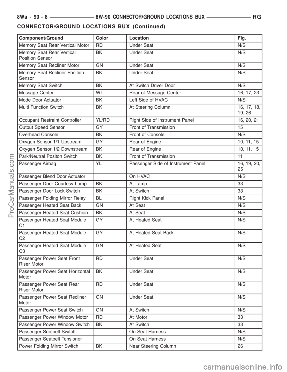
Component/Ground Color Location Fig.
Memory Seat Rear Vertical Motor RD Under Seat N/S
Memory Seat Rear Vertical
Position SensorBK Under Seat N/S
Memory Seat Recliner Motor GN Under Seat N/S
Memory Seat Recliner Position
SensorBK Under Seat N/S
Memory Seat Switch BK At Switch Driver Door N/S
Message Center WT Rear of Message Center 16, 17, 23
Mode Door Actuator BK Left Side of HVAC N/S
Multi Function Switch BK At Steering Column 16, 17, 18,
19, 26
Occupant Restraint Controller YL/RD Right Side of Instrument Panel 16, 20, 21
Output Speed Sensor GY Front of Transmission 15
Overhead Console BK Front of Console N/S
Oxygen Sensor 1/1 Upstream GY Rear of Engine 10, 11, 15
Oxygen Sensor 1/2 Downstream BK Rear of Engine 10, 11, 15
Park/Neutral Positon Switch BK Front of Transmission 11
Passenger Airbag YL Passenger Side of Instrument Panel 16, 19, 20,
25
Passenger Blend Door Actuator On HVAC N/S
Passenger Door Courtesy Lamp BK At Lamp 33
Passenger Door Lock Switch BK At Switch 33
Passenger Folding Mirror Relay BL Right Kick Panel N/S
Passenger Heated Seat Back GN At Seat N/S
Passenger Heated Seat Cushion BK At Seat N/S
Passenger Heated Seat Module
C1GY At Heated Seat N/S
Passenger Heated Seat Module
C2GY At Heated Seat Back N/S
Passenger Heated Seat Module
C3GN At Heated Seat N/S
Passenger Power Seat Front
Riser MotorRD Under Seat N/S
Passenger Power Seat Horizontal
MotorBK Under Seat N/S
Passenger Power Seat Rear
Riser MotorRD Under Seat N/S
Passenger Power Seat Recliner
MotorGN Under Seat N/S
Passenger Power Seat Switch GN At Switch N/S
Passenger Power Window Motor RD At Motor 33
Passenger Power Window Switch BK At Switch 33
Passenger Seatbelt Switch On Seat Harness N/S
Passenger Seatbelt Tensioner On Seat Harness N/S
Power Folding Mirror Switch BK Near Steering Column 26
8Wa - 90 - 8 8W-90 CONNECTOR/GROUND LOCATIONS BUXRG
CONNECTOR/GROUND LOCATIONS BUX (Continued)
ProCarManuals.com
Page 1105 of 2321
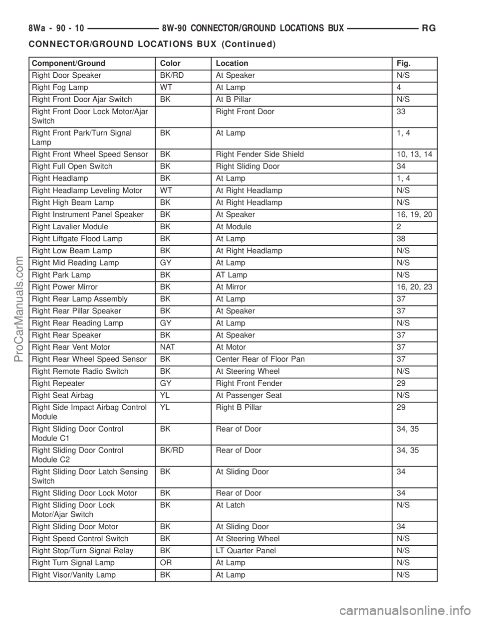
Component/Ground Color Location Fig.
Right Door Speaker BK/RD At Speaker N/S
Right Fog Lamp WT At Lamp 4
Right Front Door Ajar Switch BK At B Pillar N/S
Right Front Door Lock Motor/Ajar
SwitchRight Front Door 33
Right Front Park/Turn Signal
LampBK At Lamp 1, 4
Right Front Wheel Speed Sensor BK Right Fender Side Shield 10, 13, 14
Right Full Open Switch BK Right Sliding Door 34
Right Headlamp BK At Lamp 1, 4
Right Headlamp Leveling Motor WT At Right Headlamp N/S
Right High Beam Lamp BK At Right Headlamp N/S
Right Instrument Panel Speaker BK At Speaker 16, 19, 20
Right Lavalier Module BK At Module 2
Right Liftgate Flood Lamp BK At Lamp 38
Right Low Beam Lamp BK At Right Headlamp N/S
Right Mid Reading Lamp GY At Lamp N/S
Right Park Lamp BK AT Lamp N/S
Right Power Mirror BK At Mirror 16, 20, 23
Right Rear Lamp Assembly BK At Lamp 37
Right Rear Pillar Speaker BK At Speaker 37
Right Rear Reading Lamp GY At Lamp N/S
Right Rear Speaker BK At Speaker 37
Right Rear Vent Motor NAT At Motor 37
Right Rear Wheel Speed Sensor BK Center Rear of Floor Pan 37
Right Remote Radio Switch BK At Steering Wheel N/S
Right Repeater GY Right Front Fender 29
Right Seat Airbag YL At Passenger Seat N/S
Right Side Impact Airbag Control
ModuleYL Right B Pillar 29
Right Sliding Door Control
Module C1BK Rear of Door 34, 35
Right Sliding Door Control
Module C2BK/RD Rear of Door 34, 35
Right Sliding Door Latch Sensing
SwitchBK At Sliding Door 34
Right Sliding Door Lock Motor BK Rear of Door 34
Right Sliding Door Lock
Motor/Ajar SwitchBK At Latch N/S
Right Sliding Door Motor BK At Sliding Door 34
Right Speed Control Switch BK At Steering Wheel N/S
Right Stop/Turn Signal Relay BK LT Quarter Panel N/S
Right Turn Signal Lamp OR At Lamp N/S
Right Visor/Vanity Lamp BK At Lamp N/S
8Wa - 90 - 10 8W-90 CONNECTOR/GROUND LOCATIONS BUXRG
CONNECTOR/GROUND LOCATIONS BUX (Continued)
ProCarManuals.com
Page 1106 of 2321
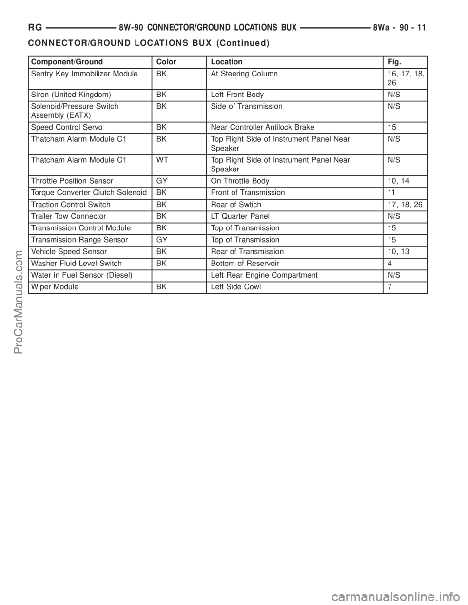
Component/Ground Color Location Fig.
Sentry Key Immobilizer Module BK At Steering Column 16, 17, 18,
26
Siren (United Kingdom) BK Left Front Body N/S
Solenoid/Pressure Switch
Assembly (EATX)BK Side of Transmission N/S
Speed Control Servo BK Near Controller Antilock Brake 15
Thatcham Alarm Module C1 BK Top Right Side of Instrument Panel Near
SpeakerN/S
Thatcham Alarm Module C1 WT Top Right Side of Instrument Panel Near
SpeakerN/S
Throttle Position Sensor GY On Throttle Body 10, 14
Torque Converter Clutch Solenoid BK Front of Transmission 11
Traction Control Switch BK Rear of Swtich 17, 18, 26
Trailer Tow Connector BK LT Quarter Panel N/S
Transmission Control Module BK Top of Transmission 15
Transmission Range Sensor GY Top of Transmission 15
Vehicle Speed Sensor BK Rear of Transmission 10, 13
Washer Fluid Level Switch BK Bottom of Reservoir 4
Water in Fuel Sensor (Diesel) Left Rear Engine Compartment N/S
Wiper Module BK Left Side Cowl 7
RG8W-90 CONNECTOR/GROUND LOCATIONS BUX8Wa-90-11
CONNECTOR/GROUND LOCATIONS BUX (Continued)
ProCarManuals.com
Page 1138 of 2321
8W-95 SPLICE LOCATIONS BUX
TABLE OF CONTENTS
page
SPLICE LOCATIONS BUX
DESCRIPTION............................1
SPLICE LOCATIONS BUX
DESCRIPTION
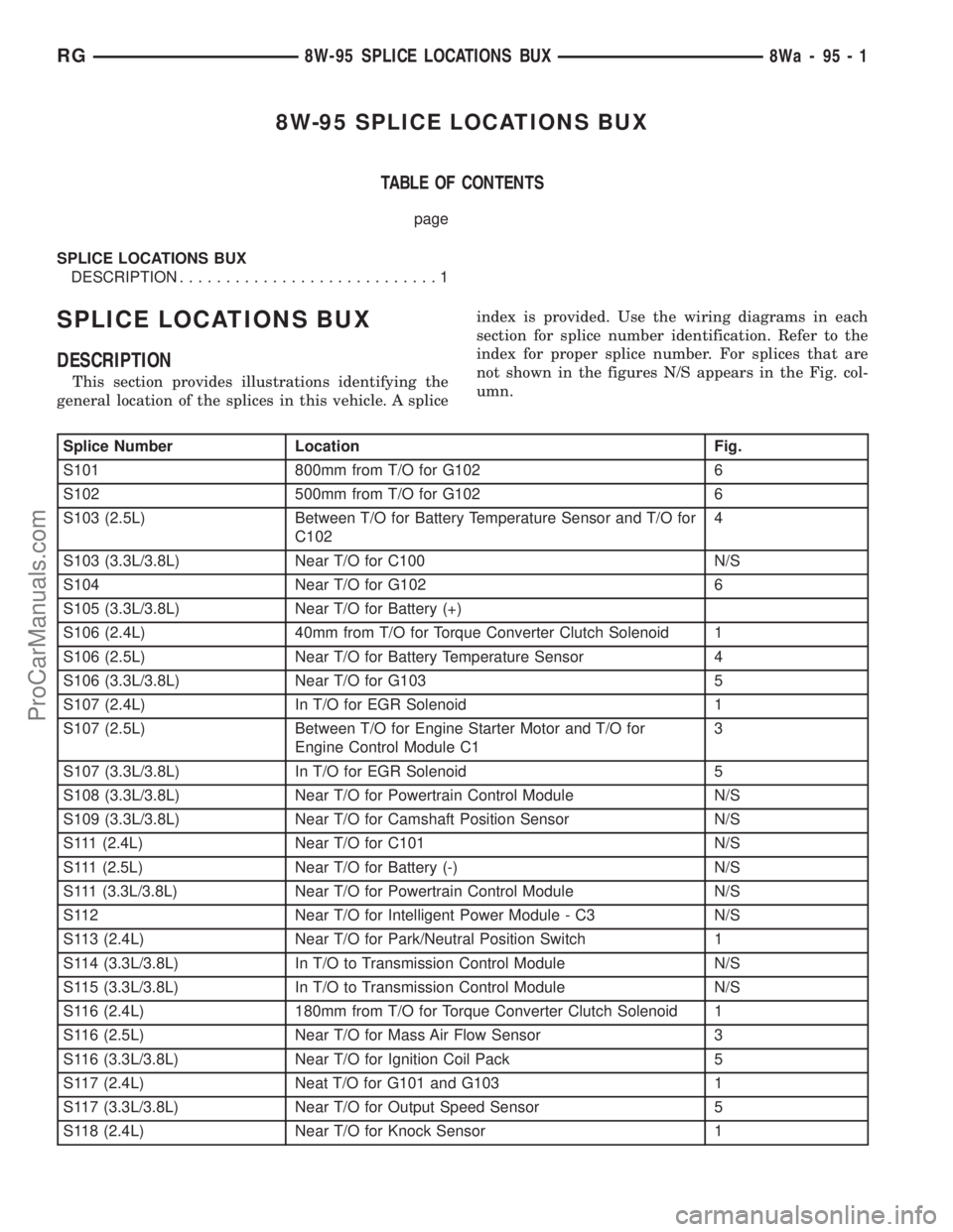
This section provides illustrations identifying the
general location of the splices in this vehicle. A spliceindex is provided. Use the wiring diagrams in each
section for splice number identification. Refer to the
index for proper splice number. For splices that are
not shown in the figures N/S appears in the Fig. col-
umn.
Splice Number Location Fig.
S101 800mm from T/O for G102 6
S102 500mm from T/O for G102 6
S103 (2.5L) Between T/O for Battery Temperature Sensor and T/O for
C1024
S103 (3.3L/3.8L) Near T/O for C100 N/S
S104 Near T/O for G102 6
S105 (3.3L/3.8L) Near T/O for Battery (+)
S106 (2.4L) 40mm from T/O for Torque Converter Clutch Solenoid 1
S106 (2.5L) Near T/O for Battery Temperature Sensor 4
S106 (3.3L/3.8L) Near T/O for G103 5
S107 (2.4L) In T/O for EGR Solenoid 1
S107 (2.5L) Between T/O for Engine Starter Motor and T/O for
Engine Control Module C13
S107 (3.3L/3.8L) In T/O for EGR Solenoid 5
S108 (3.3L/3.8L) Near T/O for Powertrain Control Module N/S
S109 (3.3L/3.8L) Near T/O for Camshaft Position Sensor N/S
S111 (2.4L) Near T/O for C101 N/S
S111 (2.5L) Near T/O for Battery (-) N/S
S111 (3.3L/3.8L) Near T/O for Powertrain Control Module N/S
S112 Near T/O for Intelligent Power Module - C3 N/S
S113 (2.4L) Near T/O for Park/Neutral Position Switch 1
S114 (3.3L/3.8L) In T/O to Transmission Control Module N/S
S115 (3.3L/3.8L) In T/O to Transmission Control Module N/S
S116 (2.4L) 180mm from T/O for Torque Converter Clutch Solenoid 1
S116 (2.5L) Near T/O for Mass Air Flow Sensor 3
S116 (3.3L/3.8L) Near T/O for Ignition Coil Pack 5
S117 (2.4L) Neat T/O for G101 and G103 1
S117 (3.3L/3.8L) Near T/O for Output Speed Sensor 5
S118 (2.4L) Near T/O for Knock Sensor 1
RG8W-95 SPLICE LOCATIONS BUX8Wa-95-1
ProCarManuals.com
Page 1139 of 2321
Splice Number Location Fig.
S119 (2.5L) Near T/O for Engine Starter Motor 4
S120 (2.4L) Near T/O for Oxygen Sensors 2
S120 (3.3L/3.8L) Near T/O for Oxygen Sensors 5
S121 (3.3L/3.8L) Near T/O for Output Speed Sensor 5
S122 (2.4L) In T/O to Engine Starter Motor 1
S122 (3.3L/3.8L) In T/O to Engine Starter Motor 5
S123 In T/O to Low Note Horn 8
S124 (2.4L) Near T/O for Fuel Injector No.2 N/S
S124 (3.3L/3.8L) Near T/O for Fuel Injector No.5 and No.6 N/S
S125 (2.4L) In T/O for Manifold Absolute Pressure Sensor N/S
S127 (2.5L) Near T/O for Engine Starter Motor N/S
S128 (2.5L) Near T/O for Engine Starter Motor 4
S129 (2.5L) Near T/O for Battery (+) N/S
S130 (2.5L) Near T/O for Battery (+) N/S
S131 (3.3L/3.8L) Near T/O for Transmission Control Module N/S
S132 (2.5L) Near T/O for Battery (+) N/S
S133 (2.5L) Near T/O for Intelligent Power Module C3 N/S
S135 (2.5L) Near T/O for Glow Plug No.2 4
S136 (2.5L) Between T/O for Radiator Fan No.2 and T/O for G102 N/S
S137 (2.5L) Near T/O for A/C Compressor Clutch 4
S138 (2.5L) Between T/O for Radiator Fan No.2 and T/O for G102 N/S
S139 (2.5L) Between T/O for Engine Starter Motor and T/O for
Engine Control Module C13
S141 (2.4L) Near T/O for Powertrain Control Module N/S
S141 (2.5L) Near /t/O for G100 N/S
S141 (3.3L/3.8L) Near T/O for Powertrain Control Module N/S
S142 (3.3L/3.8L) Near T/O for A/C Compressor Clutch 5
S143 (2.5L) Near T/O for Engine Control Module C1 4
S143 (3.3L/3.8L) Near T/O for Intelligent Power Module - C3 N/S
S144 (2.5L) Between T/O for Battery Temperature Sensor and T/O for
C1034
S145 (2.5L) Near T/O for Battery (+) N/S
S148 (2.5L) Near T/O for Engine Starter Motor 4
S150 (2.5L) Between T/O for Battery Temperature Sensor and T/O for
C103N/S
S151 (2.5L) Near T/O for Radiator Fan Relay No.1 7
S152 (2.5L) Near T/O for Left Fog Lamp N/S
S157 (2.5L) Near T/O for Glow Plug No.1 4
S187 (2.5L) Near T/O for Engine Control Module C1 4
S188 (2.5L) Near T/O for Radiator Fan Relay No.1 7
S201 In T/O to Instrument Panel Speaker 9
S202 Near T/O for Instrument Panel Switch Bank 9, 10
S203 Near T/O for Instrument Panel Switch Bank 9, 10
8Wa - 95 - 2 8W-95 SPLICE LOCATIONS BUXRG
SPLICE LOCATIONS BUX (Continued)
ProCarManuals.com
Page 1179 of 2321
AIR CLEANER ELEMENT
REMOVAL
(1) Unsnap 2 clips.
(2) Lift cover and pull toward the engine and
remove cover tabs from air box.
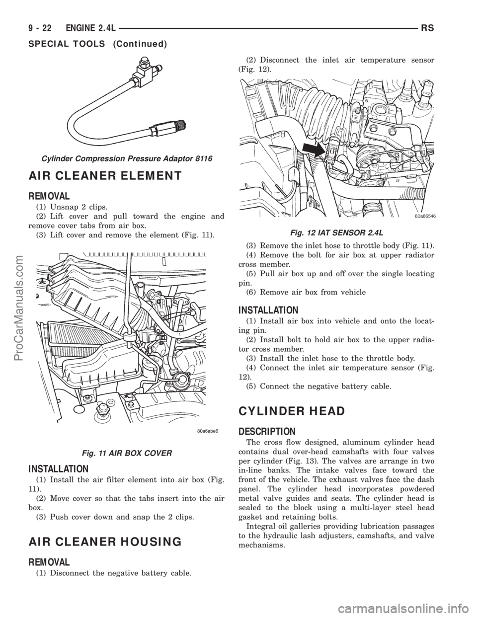
(3) Lift cover and remove the element (Fig. 11).
INSTALLATION
(1) Install the air filter element into air box (Fig.
11).
(2) Move cover so that the tabs insert into the air
box.
(3) Push cover down and snap the 2 clips.
AIR CLEANER HOUSING
REMOVAL
(1) Disconnect the negative battery cable.(2) Disconnect the inlet air temperature sensor
(Fig. 12).
(3) Remove the inlet hose to throttle body (Fig. 11).
(4) Remove the bolt for air box at upper radiator
cross member.
(5) Pull air box up and off over the single locating
pin.
(6) Remove air box from vehicle
INSTALLATION
(1) Install air box into vehicle and onto the locat-
ing pin.
(2) Install bolt to hold air box to the upper radia-
tor cross member.
(3) Install the inlet hose to the throttle body.
(4) Connect the inlet air temperature sensor (Fig.
12).
(5) Connect the negative battery cable.
CYLINDER HEAD
DESCRIPTION
The cross flow designed, aluminum cylinder head
contains dual over-head camshafts with four valves
per cylinder (Fig. 13). The valves are arrange in two
in-line banks. The intake valves face toward the
front of the vehicle. The exhaust valves face the dash
panel. The cylinder head incorporates powdered
metal valve guides and seats. The cylinder head is
sealed to the block using a multi-layer steel head
gasket and retaining bolts.
Integral oil galleries providing lubrication passages
to the hydraulic lash adjusters, camshafts, and valve
mechanisms.
Cylinder Compression Pressure Adaptor 8116
Fig. 11 AIR BOX COVER
Fig. 12 IAT SENSOR 2.4L
9 - 22 ENGINE 2.4LRS
SPECIAL TOOLS (Continued)
ProCarManuals.com
Page 1181 of 2321
(6) Remove heater tube support bracket from cyl-
inder head.
(7) Disconnect radiator upper and heater supply
hoses from intake manifold water outlet connections.
(8) Remove accessory drive belts. (Refer to 7 -
COOLING/ACCESSORY DRIVE/DRIVE BELTS -
REMOVAL)
(9) Raise vehicle and remove exhaust pipe from
manifold.
(10) Remove power steering pump reservoir and
line support bracket from lower intake manifold and
set aside. Do not disconnect lines.
(11) Remove ignition coil and wires from engine.
(12) Disconnect cam sensor and fuel injector wir-
ing connectors.
(13) Remove timing belt and camshaft sprockets.
(Refer to 9 - ENGINE/VALVE TIMING/TIMING
BELT/CHAIN AND SPROCKETS - REMOVAL)
(14) Remove timing belt idler pulley and rear tim-
ing belt cover. (Refer to 9 - ENGINE/VALVE TIM-
ING/TIMING BELT / CHAIN COVER(S) -
REMOVAL)
(15) Remove cylinder head cover. (Refer to 9 -
ENGINE/CYLINDER HEAD/CYLINDER HEAD
COVER(S) - REMOVAL)
(16) Remove camshafts (Refer to 9 - ENGINE/
CYLINDER HEAD/CAMSHAFT(S) - REMOVAL).
NOTE: Identify rocker arm position to ensure cor-
rect re-installation in original position, if reused.
(17) Remove rocker arms. (Refer to 9 - ENGINE/
CYLINDER HEAD/ROCKER ARMS - REMOVAL)
(18) Remove cylinder head bolts in REVERSE
sequence of tightening (Fig. 19).
(19) Remove cylinder head from engine block.
(20) Inspect and clean cylinder head. (Refer to 9 -
ENGINE/CYLINDER HEAD - INSPECTION) (Refer
to 9 - ENGINE/CYLINDER HEAD - CLEANING)
CLEANING
To ensure engine gasket sealing, proper surface
preparation must be performed, especially with the
use of aluminum engine components and multi-layer
steel cylinder head gaskets.
NOTE: Multi-Layer Steel (MLS) head gaskets require
a scratch free sealing surface.
Remove all gasket material from cylinder head and
block. (Refer to 9 - ENGINE - STANDARD PROCE-
DURE) Be careful not to gouge or scratch the alumi-
num head sealing surface.
Clean all engine oil passages.
INSPECTION
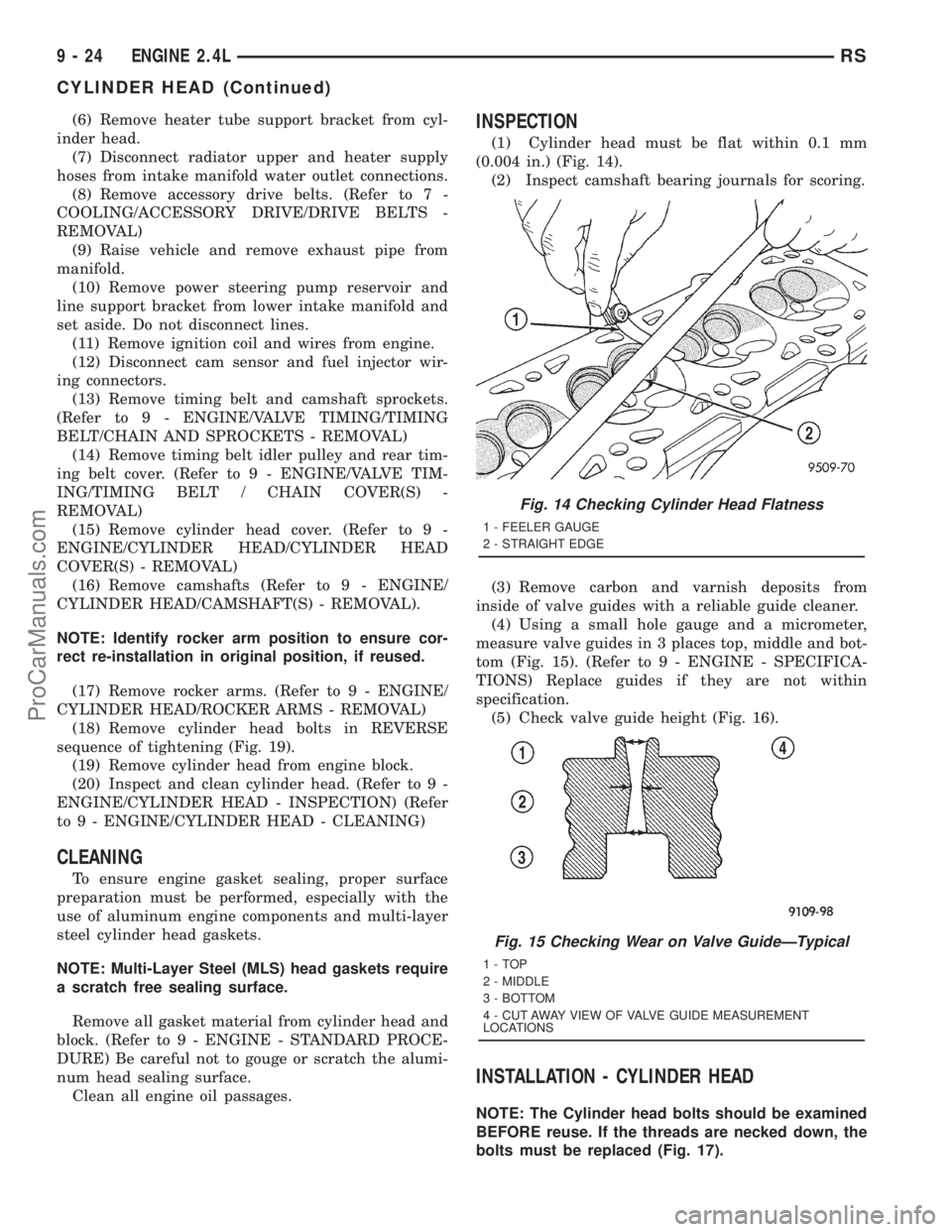
(1) Cylinder head must be flat within 0.1 mm
(0.004 in.) (Fig. 14).
(2) Inspect camshaft bearing journals for scoring.
(3) Remove carbon and varnish deposits from
inside of valve guides with a reliable guide cleaner.
(4) Using a small hole gauge and a micrometer,
measure valve guides in 3 places top, middle and bot-
tom (Fig. 15). (Refer to 9 - ENGINE - SPECIFICA-
TIONS) Replace guides if they are not within
specification.
(5) Check valve guide height (Fig. 16).
INSTALLATION - CYLINDER HEAD
NOTE: The Cylinder head bolts should be examined
BEFORE reuse. If the threads are necked down, the
bolts must be replaced (Fig. 17).
Fig. 14 Checking Cylinder Head Flatness
1 - FEELER GAUGE
2 - STRAIGHT EDGE
Fig. 15 Checking Wear on Valve GuideÐTypical
1-TOP
2 - MIDDLE
3 - BOTTOM
4 - CUT AWAY VIEW OF VALVE GUIDE MEASUREMENT
LOCATIONS
9 - 24 ENGINE 2.4LRS
CYLINDER HEAD (Continued)
ProCarManuals.com
Page 1182 of 2321
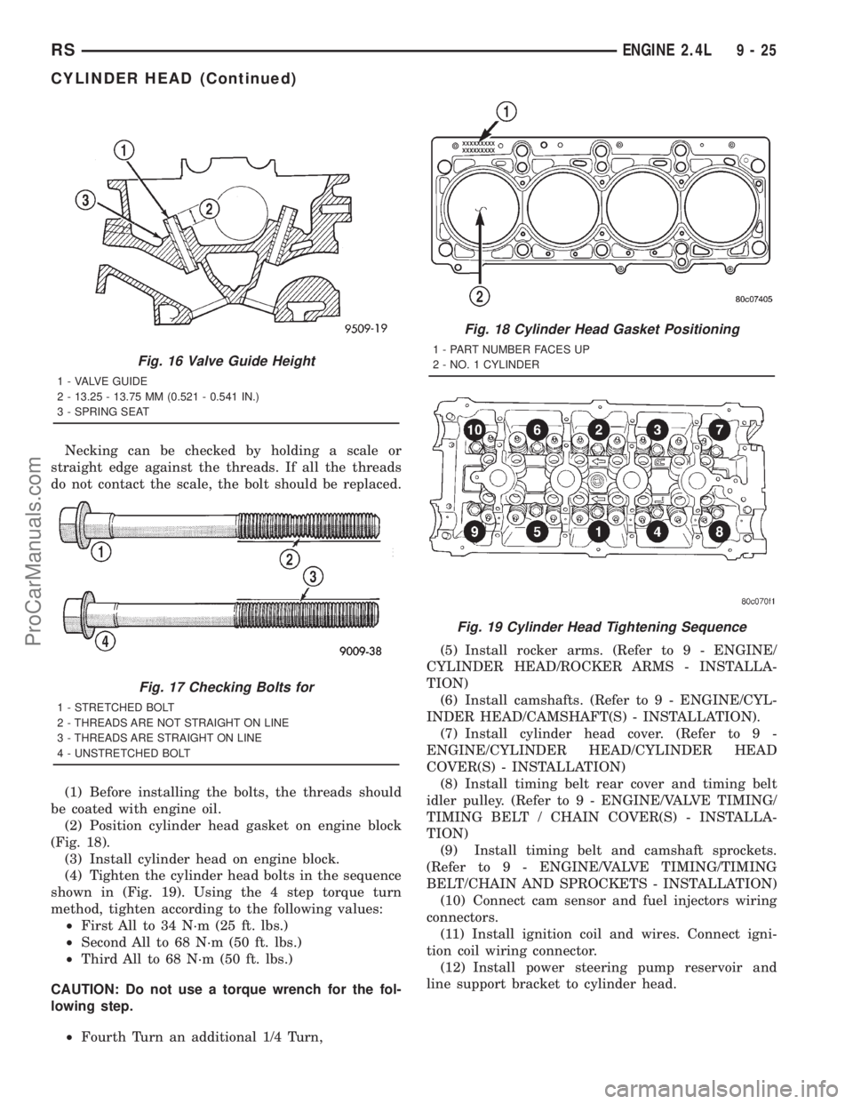
Necking can be checked by holding a scale or
straight edge against the threads. If all the threads
do not contact the scale, the bolt should be replaced.
(1) Before installing the bolts, the threads should
be coated with engine oil.
(2) Position cylinder head gasket on engine block
(Fig. 18).
(3) Install cylinder head on engine block.
(4) Tighten the cylinder head bolts in the sequence
shown in (Fig. 19). Using the 4 step torque turn
method, tighten according to the following values:
²First All to 34 N´m (25 ft. lbs.)
²Second All to 68 N´m (50 ft. lbs.)
²Third All to 68 N´m (50 ft. lbs.)
CAUTION: Do not use a torque wrench for the fol-
lowing step.
²Fourth Turn an additional 1/4 Turn,(5) Install rocker arms. (Refer to 9 - ENGINE/
CYLINDER HEAD/ROCKER ARMS - INSTALLA-
TION)
(6) Install camshafts. (Refer to 9 - ENGINE/CYL-
INDER HEAD/CAMSHAFT(S) - INSTALLATION).
(7) Install cylinder head cover. (Refer to 9 -
ENGINE/CYLINDER HEAD/CYLINDER HEAD
COVER(S) - INSTALLATION)
(8) Install timing belt rear cover and timing belt
idler pulley. (Refer to 9 - ENGINE/VALVE TIMING/
TIMING BELT / CHAIN COVER(S) - INSTALLA-
TION)
(9) Install timing belt and camshaft sprockets.
(Refer to 9 - ENGINE/VALVE TIMING/TIMING
BELT/CHAIN AND SPROCKETS - INSTALLATION)
(10) Connect cam sensor and fuel injectors wiring
connectors.
(11) Install ignition coil and wires. Connect igni-
tion coil wiring connector.
(12) Install power steering pump reservoir and
line support bracket to cylinder head.
Fig. 16 Valve Guide Height
1 - VALVE GUIDE
2 - 13.25 - 13.75 MM (0.521 - 0.541 IN.)
3 - SPRING SEAT
Fig. 17 Checking Bolts for
1 - STRETCHED BOLT
2 - THREADS ARE NOT STRAIGHT ON LINE
3 - THREADS ARE STRAIGHT ON LINE
4 - UNSTRETCHED BOLT
Fig. 18 Cylinder Head Gasket Positioning
1 - PART NUMBER FACES UP
2 - NO. 1 CYLINDER
Fig. 19 Cylinder Head Tightening Sequence
RSENGINE 2.4L9-25
CYLINDER HEAD (Continued)
ProCarManuals.com
Page 1183 of 2321
(13) Raise vehicle and install the exhaust pipe to
the manifold.
(14) Install accessory drive belts. (Refer to 7 -
COOLING/ACCESSORY DRIVE/DRIVE BELTS -
INSTALLATION)
(15) Install heater tube support bracket to cylinder
head.
(16) Connect radiator upper and heater hoses to
intake manifold water outlet connections.
(17) Install upper intake manifold. (Refer to 9 -
ENGINE/MANIFOLDS/INTAKE MANIFOLD -
INSTALLATION)
(18) Using new gaskets, install EGR tube and
tighten fasteners to 11 N´m (95 in. lbs.).
(19) Install air inlet tube and housing.
(20) Connect all vacuum lines, electrical wiring,
ground straps and fuel line.
(21) Fill cooling system. (Refer to 7 - COOLING -
STANDARD PROCEDURE)
(22) Connect battery negative cable.
CAMSHAFT OIL SEAL(S)
REMOVAL
(1) Remove timing belt. (Refer to 9 - ENGINE/
VALVE TIMING/TIMING BELT/CHAIN AND
SPROCKETS - REMOVAL)
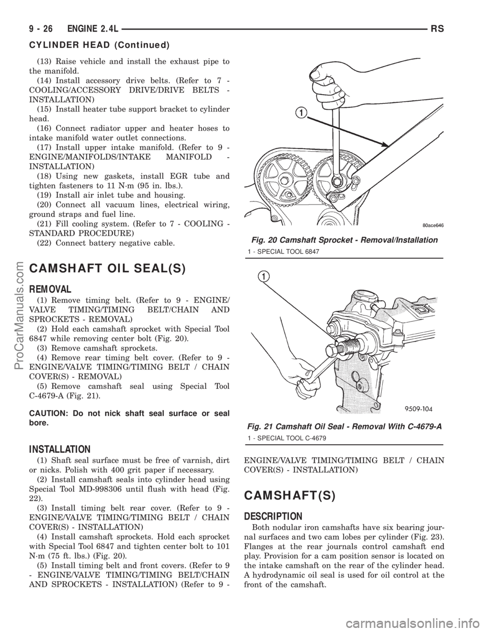
(2) Hold each camshaft sprocket with Special Tool
6847 while removing center bolt (Fig. 20).
(3) Remove camshaft sprockets.
(4) Remove rear timing belt cover. (Refer to 9 -
ENGINE/VALVE TIMING/TIMING BELT / CHAIN
COVER(S) - REMOVAL)
(5) Remove camshaft seal using Special Tool
C-4679-A (Fig. 21).
CAUTION: Do not nick shaft seal surface or seal
bore.
INSTALLATION
(1) Shaft seal surface must be free of varnish, dirt
or nicks. Polish with 400 grit paper if necessary.
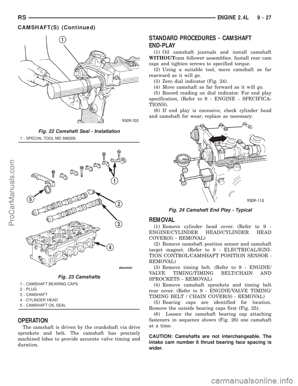
(2) Install camshaft seals into cylinder head using
Special Tool MD-998306 until flush with head (Fig.
22).
(3) Install timing belt rear cover. (Refer to 9 -
ENGINE/VALVE TIMING/TIMING BELT / CHAIN
COVER(S) - INSTALLATION)
(4) Install camshaft sprockets. Hold each sprocket
with Special Tool 6847 and tighten center bolt to 101
N´m (75 ft. lbs.) (Fig. 20).
(5) Install timing belt and front covers. (Refer to 9
- ENGINE/VALVE TIMING/TIMING BELT/CHAIN
AND SPROCKETS - INSTALLATION) (Refer to 9 -ENGINE/VALVE TIMING/TIMING BELT / CHAIN
COVER(S) - INSTALLATION)
CAMSHAFT(S)
DESCRIPTION
Both nodular iron camshafts have six bearing jour-
nal surfaces and two cam lobes per cylinder (Fig. 23).
Flanges at the rear journals control camshaft end
play. Provision for a cam position sensor is located on
the intake camshaft on the rear of the cylinder head.
A hydrodynamic oil seal is used for oil control at the
front of the camshaft.
Fig. 20 Camshaft Sprocket - Removal/Installation
1 - SPECIAL TOOL 6847
Fig. 21 Camshaft Oil Seal - Removal With C-4679-A
1 - SPECIAL TOOL C-4679
9 - 26 ENGINE 2.4LRS
CYLINDER HEAD (Continued)
ProCarManuals.com
Page 1184 of 2321
OPERATION
The camshaft is driven by the crankshaft via drive
sprockets and belt. The camshaft has precisely
machined lobes to provide accurate valve timing and
duration.
STANDARD PROCEDURES - CAMSHAFT
END-PLAY
(1) Oil camshaft journals and install camshaft
WITHOUTcam follower assemblies. Install rear cam
caps and tighten screws to specified torque.
(2) Using a suitable tool, move camshaft as far
rearward as it will go.
(3) Zero dial indicator (Fig. 24).
(4) Move camshaft as far forward as it will go.
(5) Record reading on dial indicator. For end play
specification, (Refer to 9 - ENGINE - SPECIFICA-
TIONS).
(6) If end play is excessive, check cylinder head
and camshaft for wear; replace as necessary.
REMOVAL
(1) Remove cylinder head cover. (Refer to 9 -
ENGINE/CYLINDER HEAD/CYLINDER HEAD
COVER(S) - REMOVAL)
(2) Remove camshaft position sensor and camshaft
target magnet. (Refer to 8 - ELECTRICAL/IGNI-
TION CONTROL/CAMSHAFT POSITION SENSOR -
REMOVAL)
(3) Remove timing belt. (Refer to 9 - ENGINE/
VALVE TIMING/TIMING BELT/CHAIN AND
SPROCKETS - REMOVAL)
(4) Remove camshaft sprockets and timing belt
rear cover. (Refer to 9 - ENGINE/VALVE TIMING/
TIMING BELT / CHAIN COVER(S) - REMOVAL)
(5) Bearing caps are identified for location.
Remove the outside bearing caps first (Fig. 25).
(6) Loosen the camshaft bearing cap attaching
fasteners in sequence shown (Fig. 26) one camshaft
at a time.
CAUTION: Camshafts are not interchangeable. The
intake cam number 6 thrust bearing face spacing is
wider.
Fig. 22 Camshaft Seal - Installation
1 - SPECIAL TOOL MD 998306
Fig. 23 Camshafts
1 - CAMSHAFT BEARING CAPS
2 - PLUG
3 - CAMSHAFT
4 - CYLINDER HEAD
5 - CAMSHAFT OIL SEAL
Fig. 24 Camshaft End Play - Typical
RSENGINE 2.4L9-27
CAMSHAFT(S) (Continued)
ProCarManuals.com