service reset DODGE TOWN AND COUNTRY 2001 User Guide
[x] Cancel search | Manufacturer: DODGE, Model Year: 2001, Model line: TOWN AND COUNTRY, Model: DODGE TOWN AND COUNTRY 2001Pages: 2321, PDF Size: 68.09 MB
Page 564 of 2321

trically and independently using the separate power
seat switches found on the outboard seat cushion
side shield of each front seat. See the owner's manual
in the vehicle glove box for more information on the
features, use and operation of the power seat system.
OPERATION - MEMORY SYSTEM
The Memory Seat/Mirror Module (MSMM) will
drive a maximum of 2 motors at a time in a given
direction. If conflicting directions are requested, the
priority for response will be as follows:
²Seat Track Rearward
²Seat Front Down
²Seat Rear Down
²Recliner Rearward
²Seat Track Forward
²Seat Front Up
²Seat Rear Up
²Recliner Forward
The inputs from these switches to the MSMM is a
current limited battery source fed by the MSMM.
This protects the MSMM printed circuit board traces
from acting as fuses. All of these switch contact
inputs to the MSMM are normally closed to ground,
except when actuated.
Soft stops are incorporated to prevent the motor
from being driven into a stall. Should the seat have
restricted travel, refer to Resetting Soft Stops in this
section.
See the owner's manual in the vehicle glove box for
more information on the features, use and operation
of the memory system. For diagnosis of the MSM, the
PCI data bus, or the other electronic modules on the
PCI data bus that provide inputs and outputs for the
memory system, the use of a DRBtscan tool and the
proper Diagnostic Procedures manual are recom-
mended.
ELECTRONIC VEHICLE INFORMATION CENTER
The Electronic Vehicle Information Center (EVIC)
serves as the user interface for the memory system.
It displays memory system status messages and pro-
vides the user with the means for enabling and dis-
abling the many customer programmable features
available on the vehicle, including those for the mem-
ory system.
See the owner's manual in the vehicle glove box for
more information on the features, use and operation
of the EVIC. Refer toElectronic Vehicle Informa-
tion Centerin Overhead Console Systems for more
information on the EVIC.
DIAGNOSIS AND TESTING - POWER SEAT
SYSTEM
Following are tests that will help to diagnose the
hard wired components and circuits of the power seatsystem. However, if the vehicle is also equipped with
the optional memory system, these tests may not
prove conclusive in the diagnosis of the driver side
power seat. In order to obtain conclusive testing of
the driver side power seat with the memory system
option, the Programmable Communications Interface
(PCI) data bus network and all of the electronic mod-
ules that provide inputs to, or receive outputs from
the memory system components must be checked.
The most reliable, efficient, and accurate means to
diagnose the driver side power seat with the memory
system option requires the use of a DRBtscan tool
and the proper Diagnostic Procedures manual. The
DRBtscan tool can provide confirmation that the
PCI data bus is functional, that all of the electronic
modules are sending and receiving the proper mes-
sages on the PCI data bus, and that the memory sys-
tem is receiving the proper hard wired inputs and
relaying the proper hard wired outputs to perform its
driver side power seat functions.
WARNING: SOME VEHICLES ARE EQUIPPED WITH
SEATBACK MOUNTED AIRBAGS (Fig. 1). BEFORE
ATTEMPTING TO DIAGNOSE OR SERVICE ANY
SEAT OR POWER SEAT SYSTEM COMPONENT
YOU MUST FIRST DISCONNECT AND ISOLATE THE
BATTERY NEGATIVE CABLE. THEN WAIT TWO MIN-
UTES FOR THE SYSTEM CAPACITOR TO DIS-
CHARGE BEFORE FURTHER SYSTEM SERVICE.
THIS IS THE ONLY SURE WAY TO DISABLE THE
AIRBAG SYSTEM. FAILURE TO DO SO COULD
RESULT IN ACCIDENTAL AIRBAG DEPLOYMENT
AND POSSIBLE PERSONAL INJURY.
Before any testing of the power seat system is
attempted, the battery should be fully-charged and
all of the power seat system wire harness connections
and pins cleaned and tightened to ensure proper cir-
cuit continuity and ground paths. For complete cir-
cuit diagrams, refer toPower Seatin Wiring
Diagrams.
With the dome lamp on, apply the power seat
switch in the direction of the failure. If the dome
lamp dims, the seat may be jamming. Check under
and behind the seat for binding or obstructions. If
the dome lamp does not dim, proceed with testing of
the individual components and circuits.
DIAGNOSIS AND TESTING - MEMORY SYSTEM
CHECK AND RESET SOFT STOPS
To check and reset the power memory seat soft
stops, use the power seat control switches to move
the seat in one direction to the end of travel, allow a
couple of seconds before re-energizing the seat in the
same direction until it stops and for three additional
seconds after it stops. (The amount the seat moved
RSPOWER SEATS8N-51
POWER SEATS (Continued)
ProCarManuals.com
Page 566 of 2321

limit of the adjuster is reached. When the switch is
moved in the opposite direction, the battery feed and
ground path to the motor are reversed through the
switch contacts. This causes the adjuster motor to
run in the opposite direction.
No power seat switch should be held applied in any
direction after the adjuster has reached its travel
limit. The power seat adjuster motors each contain a
self-resetting circuit breaker to protect them from
overload. However, consecutive or frequent resetting
of the circuit breaker must not be allowed to con-
tinue, or the motor may be damaged.
DIAGNOSIS AND TESTING - DRIVER SEAT
SWITCH
(1) Remove switch, refer to Switch Removal and
Installation in this section.
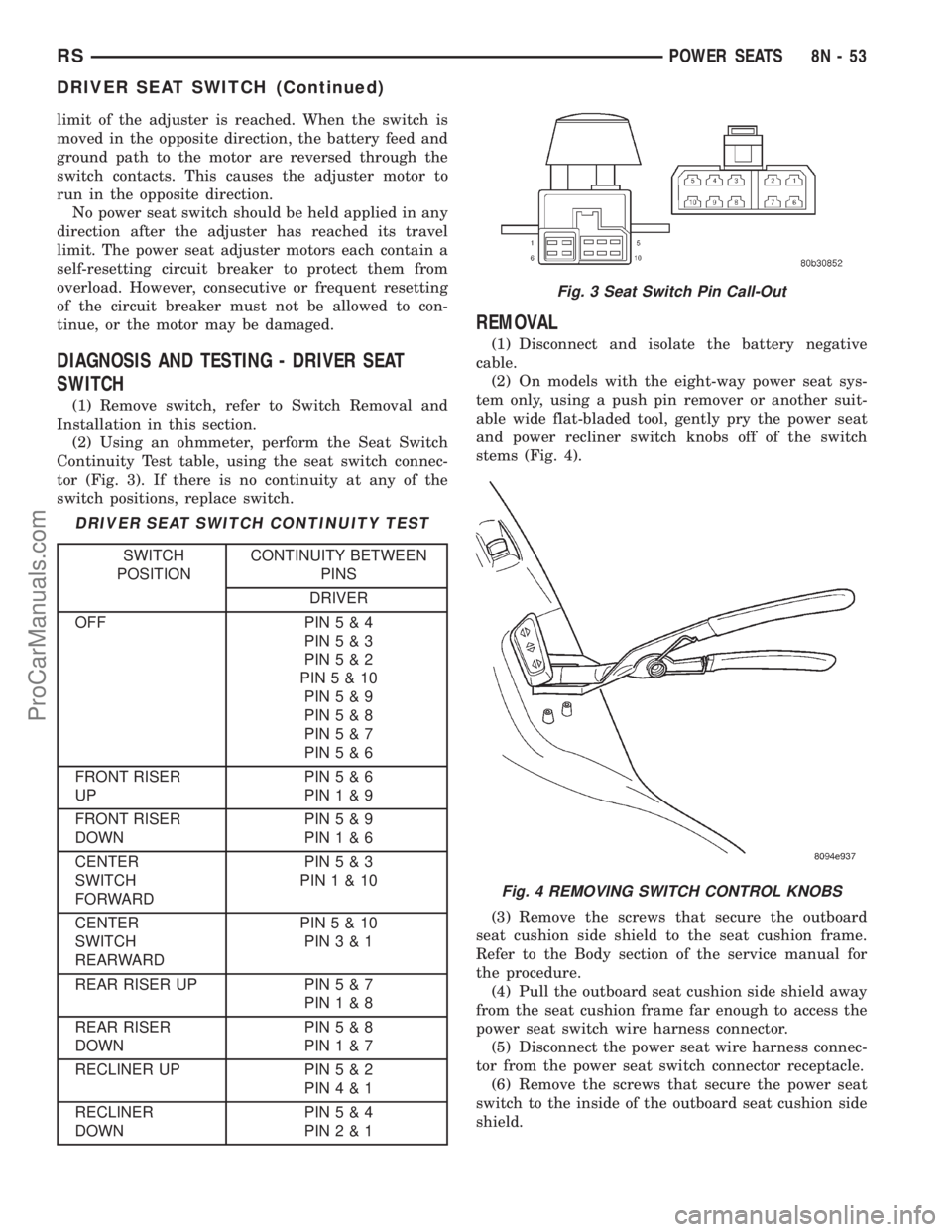
(2) Using an ohmmeter, perform the Seat Switch
Continuity Test table, using the seat switch connec-
tor (Fig. 3). If there is no continuity at any of the
switch positions, replace switch.
DRIVER SEAT SWITCH CONTINUITY TEST
SWITCH
POSITIONCONTINUITY BETWEEN
PINS
DRIVER
OFF PIN5&4
PIN5&3
PIN5&2
PIN5&10
PIN5&9
PIN5&8
PIN5&7
PIN5&6
FRONT RISER
UPPIN5&6
PIN1&9
FRONT RISER
DOWNPIN5&9
PIN1&6
CENTER
SWITCH
FORWARDPIN5&3
PIN1&10
CENTER
SWITCH
REARWARDPIN5&10
PIN3&1
REAR RISER UP PIN5&7
PIN1&8
REAR RISER
DOWNPIN5&8
PIN1&7
RECLINER UP PIN5&2
PIN4&1
RECLINER
DOWNPIN5&4
PIN2&1
REMOVAL
(1) Disconnect and isolate the battery negative
cable.
(2) On models with the eight-way power seat sys-
tem only, using a push pin remover or another suit-
able wide flat-bladed tool, gently pry the power seat
and power recliner switch knobs off of the switch
stems (Fig. 4).
(3) Remove the screws that secure the outboard
seat cushion side shield to the seat cushion frame.
Refer to the Body section of the service manual for
the procedure.
(4) Pull the outboard seat cushion side shield away
from the seat cushion frame far enough to access the
power seat switch wire harness connector.
(5) Disconnect the power seat wire harness connec-
tor from the power seat switch connector receptacle.
(6) Remove the screws that secure the power seat
switch to the inside of the outboard seat cushion side
shield.
Fig. 3 Seat Switch Pin Call-Out
Fig. 4 REMOVING SWITCH CONTROL KNOBS
RSPOWER SEATS8N-53
DRIVER SEAT SWITCH (Continued)
ProCarManuals.com
Page 1706 of 2321

INSTALLATION
NOTE: If transaxle assembly has been replaced or
overhauled (clutch and/or seal replacement), it is
necessary to perfrom the TCM Quick Learn proce-
dure. (Refer to 8 - ELECTRICAL/ELECTRONIC CON-
TROL MODULES/TRANSMISSION CONTROL
MODULE - STANDARD PROCEDURE)
NOTE: If torque converter assembly has been
replaced, it is necessary to reset the TCC Break-In
Strategy. (Refer to 8 - ELECTRICAL/ELECTRONIC
CONTROL MODULES/TRANSMISSION CONTROL
MODULE - STANDARD PROCEDURE)
(1) Using a transmission jack and a helper, posi-
tion transaxle assembly to engine. Install and torque
bolts to 95 N´m (70 ft. lbs.).
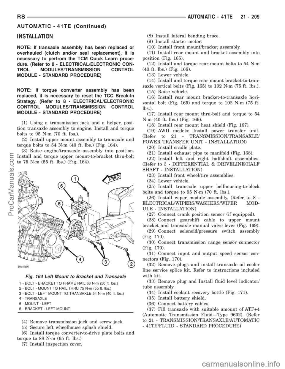
(2) Install upper mount assembly to transaxle and
torque bolts to 54 N´m (40 ft. lbs.) (Fig. 164).
(3) Raise engine/transaxle assembly into position.
Install and torque upper mount-to-bracket thru-bolt
to 75 N´m (55 ft. lbs.) (Fig. 164).
(4) Remove transmission jack and screw jack.
(5) Secure left wheelhouse splash shield.
(6) Install torque converter-to-drive plate bolts and
torque to 88 N´m (65 ft. lbs.)
(7) Install inspection cover.(8) Install lateral bending brace.
(9) Install starter motor.
(10) Install front mount/bracket assembly.
(11) Install rear mount and bracket assembly into
position (Fig. 165).
(12) Install and torque rear mount bolts to 54 N´m
(40 ft. lbs.) (Fig. 166).
(13) Lower vehicle.
(14) Install and torque rear mount bracket-to-tran-
saxle vertical bolts (Fig. 165) to 102 N´m (75 ft. lbs.).
(15) Raise vehicle.
(16) Install rear mount bracket-to-transaxle hori-
zontal bolt (Fig. 165) and torque to 102 N´m (75 ft.
lbs.).
(17) Install rear mount thru-bolt and torque to 54
N´m (40 ft. lbs.) (Fig. 166).
(18) Install rear mount heat shield (Fig. 167).
(19) AWD models: Install power transfer unit.
(Refer to 21 - TRANSMISSION/TRANSAXLE/
POWER TRANSFER UNIT - INSTALLATION)
(20) Install cradle plate.
(21) Install exhaust pipe to manifold (Fig. 168).
(22) Install left and right halfshaft assemblies.
(Refer to 3 - DIFFERENTIAL & DRIVELINE/HALF
SHAFT - INSTALLATION)
(23) Install front wheel/tire assemblies.
(24) Lower vehicle.
(25) Install transaxle upper bellhousing-to-block
bolts and torque to 95 N´m (70 ft. lbs.).
(26) Install wiper module assembly. (Refer to 8 -
ELECTRICAL/WIPERS/WASHERS/WIPER MOD-
ULE - INSTALLATION)
(27) Connect crank position sensor (if equipped).
(28) Connect gearshift cable to upper mount
bracket and transaxle manual valve lever (Fig. 169).
(29) Connect solenoid/pressure switch assembly
(Fig. 170).
(30) Connect transmission range sensor connector
(Fig. 170).
(31) Connect input and output speed sensor con-
nectors (Fig. 170).
(32) Remove plugs and install transaxle oil cooler
line service splice kit. Refer to instructions included
with kit.
(33) Remove plug and Install fluid level indicator/
tube assembly.
(34) Install coolant recovery bottle (Fig. 171).
(35) Install battery shield.
(36) Connect battery cables.
(37) Fill transaxle with suitable amount of ATF+4
(Automatic Transmission FluidÐType 9602). (Refer
to 21 - TRANSMISSION/TRANSAXLE/AUTOMATIC
- 41TE/FLUID - STANDARD PROCEDURE)
Fig. 164 Left Mount to Bracket and Transaxle
1 - BOLT - BRACKET TO FRAME RAIL 68 N´m (50 ft. lbs.)
2 - BOLT - MOUNT TO RAIL THRU 75 N´m (55 ft. lbs.)
3 - BOLT - LEFT MOUNT TO TRANSAXLE 54 N´m (40 ft. lbs.)
4 - TRANSAXLE
5 - MOUNT - LEFT
6 - BRACKET - LEFT MOUNT
RSAUTOMATIC - 41TE21 - 209
AUTOMATIC - 41TE (Continued)
ProCarManuals.com
Page 1784 of 2321

TRANSMISSION CONTROL
RELAY
DESCRIPTION
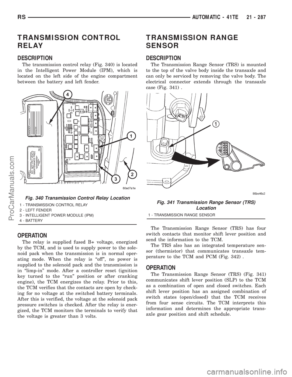
The transmission control relay (Fig. 340) is located
in the Intelligent Power Module (IPM), which is
located on the left side of the engine compartment
between the battery and left fender.
OPERATION
The relay is supplied fused B+ voltage, energized
by the TCM, and is used to supply power to the sole-
noid pack when the transmission is in normal oper-
ating mode. When the relay is ªoffº, no power is
supplied to the solenoid pack and the transmission is
in ªlimp-inº mode. After a controller reset (ignition
key turned to the ªrunº position or after cranking
engine), the TCM energizes the relay. Prior to this,
the TCM verifies that the contacts are open by check-
ing for no voltage at the switched battery terminals.
After this is verified, the voltage at the solenoid pack
pressure switches is checked. After the relay is ener-
gized, the TCM monitors the terminals to verify that
the voltage is greater than 3 volts.
TRANSMISSION RANGE
SENSOR
DESCRIPTION
The Transmission Range Sensor (TRS) is mounted
to the top of the valve body inside the transaxle and
can only be serviced by removing the valve body. The
electrical connector extends through the transaxle
case (Fig. 341) .
The Transmission Range Sensor (TRS) has four
switch contacts that monitor shift lever position and
send the information to the TCM.
The TRS also has an integrated temperature sen-
sor (thermistor) that communicates transaxle tem-
perature to the TCM and PCM (Fig. 342) .
OPERATION
The Transmission Range Sensor (TRS) (Fig. 341)
communicates shift lever position (SLP) to the TCM
as a combination of open and closed switches. Each
shift lever position has an assigned combination of
switch states (open/closed) that the TCM receives
from four sense circuits. The TCM interprets this
information and determines the appropriate trans-
axle gear position and shift schedule.
Fig. 340 Transmission Control Relay Location
1 - TRANSMISSION CONTROL RELAY
2 - LEFT FENDER
3 - INTELLIGENT POWER MODULE (IPM)
4 - BATTERYFig. 341 Transmission Range Sensor (TRS)
Location
1 - TRANSMISSION RANGE SENSOR
RSAUTOMATIC - 41TE21 - 287
ProCarManuals.com