Window control DODGE TOWN AND COUNTRY 2001 Owner's Manual
[x] Cancel search | Manufacturer: DODGE, Model Year: 2001, Model line: TOWN AND COUNTRY, Model: DODGE TOWN AND COUNTRY 2001Pages: 2321, PDF Size: 68.09 MB
Page 1043 of 2321
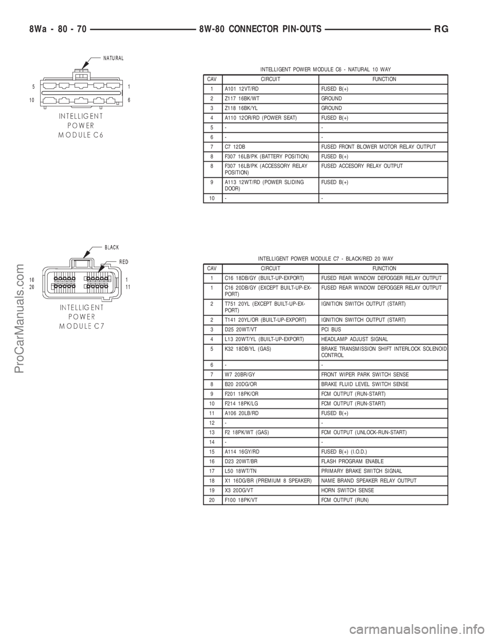
INTELLIGENT POWER MODULE C6 - NATURAL 10 WAY
CAV CIRCUIT FUNCTION
1 A101 12VT/RD FUSED B(+)
2 Z117 16BK/WT GROUND
3 Z118 16BK/YL GROUND
4 A110 12OR/RD (POWER SEAT) FUSED B(+)
5- -
6- -
7 C7 12DB FUSED FRONT BLOWER MOTOR RELAY OUTPUT
8 F307 16LB/PK (BATTERY POSITION) FUSED B(+)
8 F307 16LB/PK (ACCESSORY RELAY
POSITION)FUSED ACCESORY RELAY OUTPUT
9 A113 12WT/RD (POWER SLIDING
DOOR)FUSED B(+)
10 - -
INTELLIGENT POWER MODULE C7 - BLACK/RED 20 WAY
CAV CIRCUIT FUNCTION
1 C16 18DB/GY (BUILT-UP-EXPORT) FUSED REAR WINDOW DEFOGGER RELAY OUTPUT
1 C16 20DB/GY (EXCEPT BUILT-UP-EX-
PORT)FUSED REAR WINDOW DEFOGGER RELAY OUTPUT
2 T751 20YL (EXCEPT BUILT-UP-EX-
PORT)IGNITION SWITCH OUTPUT (START)
2 T141 20YL/OR (BUILT-UP-EXPORT) IGNITION SWITCH OUTPUT (START)
3 D25 20WT/VT PCI BUS
4 L13 20WT/YL (BUILT-UP-EXPORT) HEADLAMP ADJUST SIGNAL
5 K32 18DB/YL (GAS) BRAKE TRANSMISSION SHIFT INTERLOCK SOLENOID
CONTROL
6- -
7 W7 20BR/GY FRONT WIPER PARK SWITCH SENSE
8 B20 20DG/OR BRAKE FLUID LEVEL SWITCH SENSE
9 F201 18PK/OR FCM OUTPUT (RUN-START)
10 F214 18PK/LG FCM OUTPUT (RUN-START)
11 A106 20LB/RD FUSED B(+)
12 - -
13 F2 18PK/WT (GAS) FCM OUTPUT (UNLOCK-RUN-START)
14 - -
15 A114 16GY/RD FUSED B(+) (I.O.D.)
16 D23 20WT/BR FLASH PROGRAM ENABLE
17 L50 18WT/TN PRIMARY BRAKE SWITCH SIGNAL
18 X1 16DG/BR (PREMIUM 8 SPEAKER) NAME BRAND SPEAKER RELAY OUTPUT
19 X3 20DG/VT HORN SWITCH SENSE
20 F100 18PK/VT FCM OUTPUT (RUN)
8Wa - 80 - 70 8W-80 CONNECTOR PIN-OUTSRG
ProCarManuals.com
Page 1044 of 2321
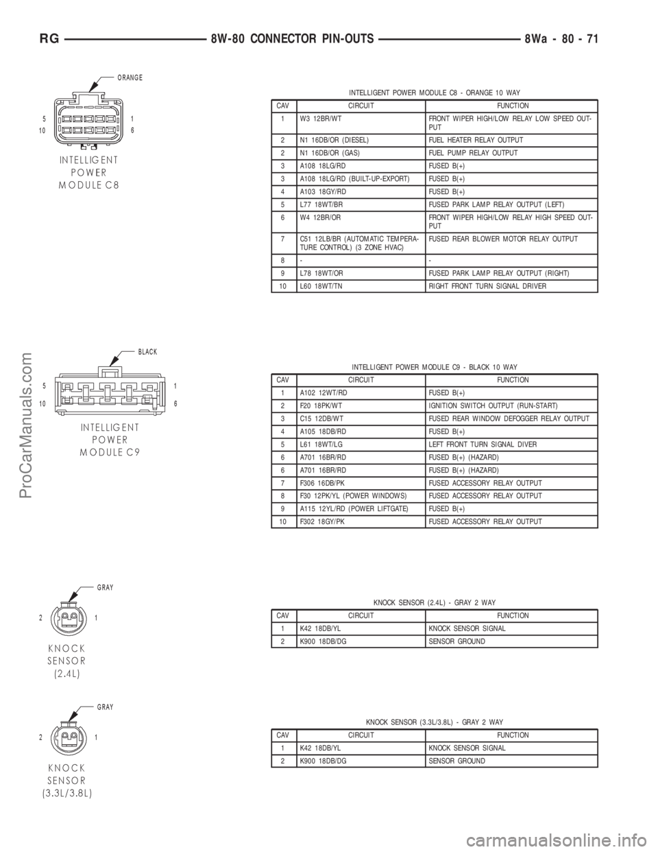
INTELLIGENT POWER MODULE C8 - ORANGE 10 WAY
CAV CIRCUIT FUNCTION
1 W3 12BR/WT FRONT WIPER HIGH/LOW RELAY LOW SPEED OUT-
PUT
2 N1 16DB/OR (DIESEL) FUEL HEATER RELAY OUTPUT
2 N1 16DB/OR (GAS) FUEL PUMP RELAY OUTPUT
3 A108 18LG/RD FUSED B(+)
3 A108 18LG/RD (BUILT-UP-EXPORT) FUSED B(+)
4 A103 18GY/RD FUSED B(+)
5 L77 18WT/BR FUSED PARK LAMP RELAY OUTPUT (LEFT)
6 W4 12BR/OR FRONT WIPER HIGH/LOW RELAY HIGH SPEED OUT-
PUT
7 C51 12LB/BR (AUTOMATIC TEMPERA-
TURE CONTROL) (3 ZONE HVAC)FUSED REAR BLOWER MOTOR RELAY OUTPUT
8- -
9 L78 18WT/OR FUSED PARK LAMP RELAY OUTPUT (RIGHT)
10 L60 18WT/TN RIGHT FRONT TURN SIGNAL DRIVER
INTELLIGENT POWER MODULE C9 - BLACK 10 WAY
CAV CIRCUIT FUNCTION
1 A102 12WT/RD FUSED B(+)
2 F20 18PK/WT IGNITION SWITCH OUTPUT (RUN-START)
3 C15 12DB/WT FUSED REAR WINDOW DEFOGGER RELAY OUTPUT
4 A105 18DB/RD FUSED B(+)
5 L61 18WT/LG LEFT FRONT TURN SIGNAL DIVER
6 A701 16BR/RD FUSED B(+) (HAZARD)
6 A701 16BR/RD FUSED B(+) (HAZARD)
7 F306 16DB/PK FUSED ACCESSORY RELAY OUTPUT
8 F30 12PK/YL (POWER WINDOWS) FUSED ACCESSORY RELAY OUTPUT
9 A115 12YL/RD (POWER LIFTGATE) FUSED B(+)
10 F302 18GY/PK FUSED ACCESSORY RELAY OUTPUT
KNOCK SENSOR (2.4L) - GRAY 2 WAY
CAV CIRCUIT FUNCTION
1 K42 18DB/YL KNOCK SENSOR SIGNAL
2 K900 18DB/DG SENSOR GROUND
KNOCK SENSOR (3.3L/3.8L) - GRAY 2 WAY
CAV CIRCUIT FUNCTION
1 K42 18DB/YL KNOCK SENSOR SIGNAL
2 K900 18DB/DG SENSOR GROUND
RG8W-80 CONNECTOR PIN-OUTS8Wa-80-71
ProCarManuals.com
Page 1064 of 2321
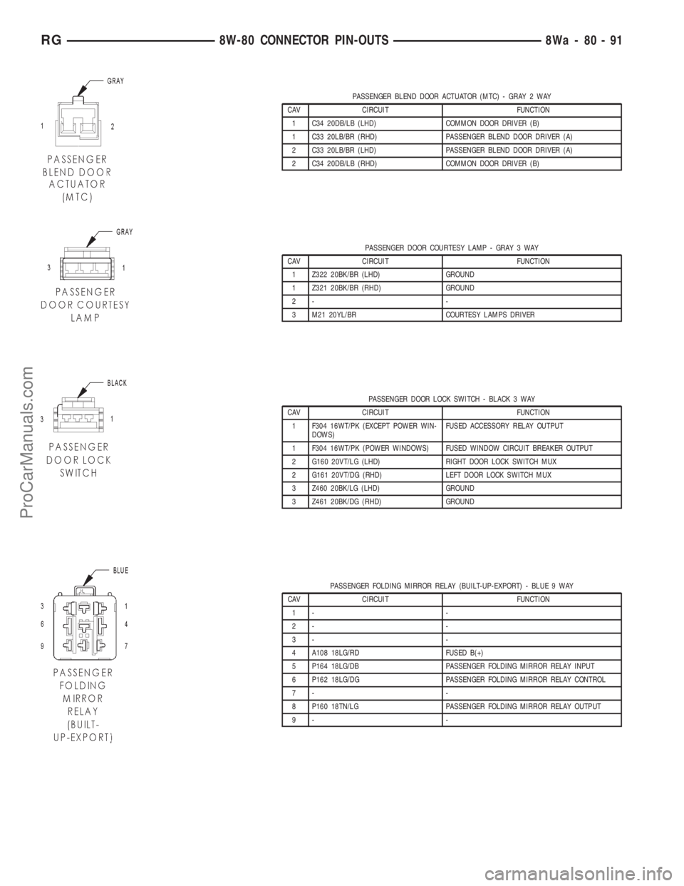
PASSENGER BLEND DOOR ACTUATOR (MTC) - GRAY 2 WAY
CAV CIRCUIT FUNCTION
1 C34 20DB/LB (LHD) COMMON DOOR DRIVER (B)
1 C33 20LB/BR (RHD) PASSENGER BLEND DOOR DRIVER (A)
2 C33 20LB/BR (LHD) PASSENGER BLEND DOOR DRIVER (A)
2 C34 20DB/LB (RHD) COMMON DOOR DRIVER (B)
PASSENGER DOOR COURTESY LAMP - GRAY 3 WAY
CAV CIRCUIT FUNCTION
1 Z322 20BK/BR (LHD) GROUND
1 Z321 20BK/BR (RHD) GROUND
2- -
3 M21 20YL/BR COURTESY LAMPS DRIVER
PASSENGER DOOR LOCK SWITCH - BLACK 3 WAY
CAV CIRCUIT FUNCTION
1 F304 16WT/PK (EXCEPT POWER WIN-
DOWS)FUSED ACCESSORY RELAY OUTPUT
1 F304 16WT/PK (POWER WINDOWS) FUSED WINDOW CIRCUIT BREAKER OUTPUT
2 G160 20VT/LG (LHD) RIGHT DOOR LOCK SWITCH MUX
2 G161 20VT/DG (RHD) LEFT DOOR LOCK SWITCH MUX
3 Z460 20BK/LG (LHD) GROUND
3 Z461 20BK/DG (RHD) GROUND
PASSENGER FOLDING MIRROR RELAY (BUILT-UP-EXPORT) - BLUE 9 WAY
CAV CIRCUIT FUNCTION
1- -
2- -
3- -
4 A108 18LG/RD FUSED B(+)
5 P164 18LG/DB PASSENGER FOLDING MIRROR RELAY INPUT
6 P162 18LG/DG PASSENGER FOLDING MIRROR RELAY CONTROL
7- -
8 P160 18TN/LG PASSENGER FOLDING MIRROR RELAY OUTPUT
9- -
RG8W-80 CONNECTOR PIN-OUTS8Wa-80-91
ProCarManuals.com
Page 1073 of 2321
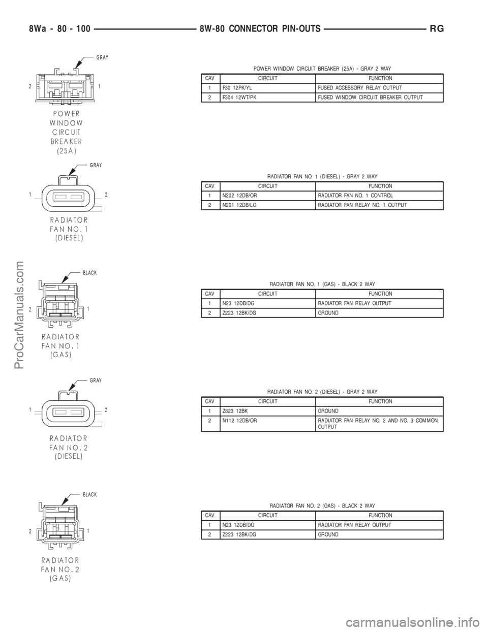
POWER WINDOW CIRCUIT BREAKER (25A) - GRAY 2 WAY
CAV CIRCUIT FUNCTION
1 F30 12PK/YL FUSED ACCESSORY RELAY OUTPUT
2 F304 12WT/PK FUSED WINDOW CIRCUIT BREAKER OUTPUT
RADIATOR FAN NO. 1 (DIESEL) - GRAY 2 WAY
CAV CIRCUIT FUNCTION
1 N202 12DB/OR RADIATOR FAN NO. 1 CONTROL
2 N201 12DB/LG RADIATOR FAN RELAY NO. 1 OUTPUT
RADIATOR FAN NO. 1 (GAS) - BLACK 2 WAY
CAV CIRCUIT FUNCTION
1 N23 12DB/DG RADIATOR FAN RELAY OUTPUT
2 Z223 12BK/DG GROUND
RADIATOR FAN NO. 2 (DIESEL) - GRAY 2 WAY
CAV CIRCUIT FUNCTION
1 Z823 12BK GROUND
2 N112 12DB/OR RADIATOR FAN RELAY NO. 2 AND NO. 3 COMMON
OUTPUT
RADIATOR FAN NO. 2 (GAS) - BLACK 2 WAY
CAV CIRCUIT FUNCTION
1 N23 12DB/DG RADIATOR FAN RELAY OUTPUT
2 Z223 12BK/DG GROUND
8Wa - 80 - 100 8W-80 CONNECTOR PIN-OUTSRG
ProCarManuals.com
Page 1099 of 2321
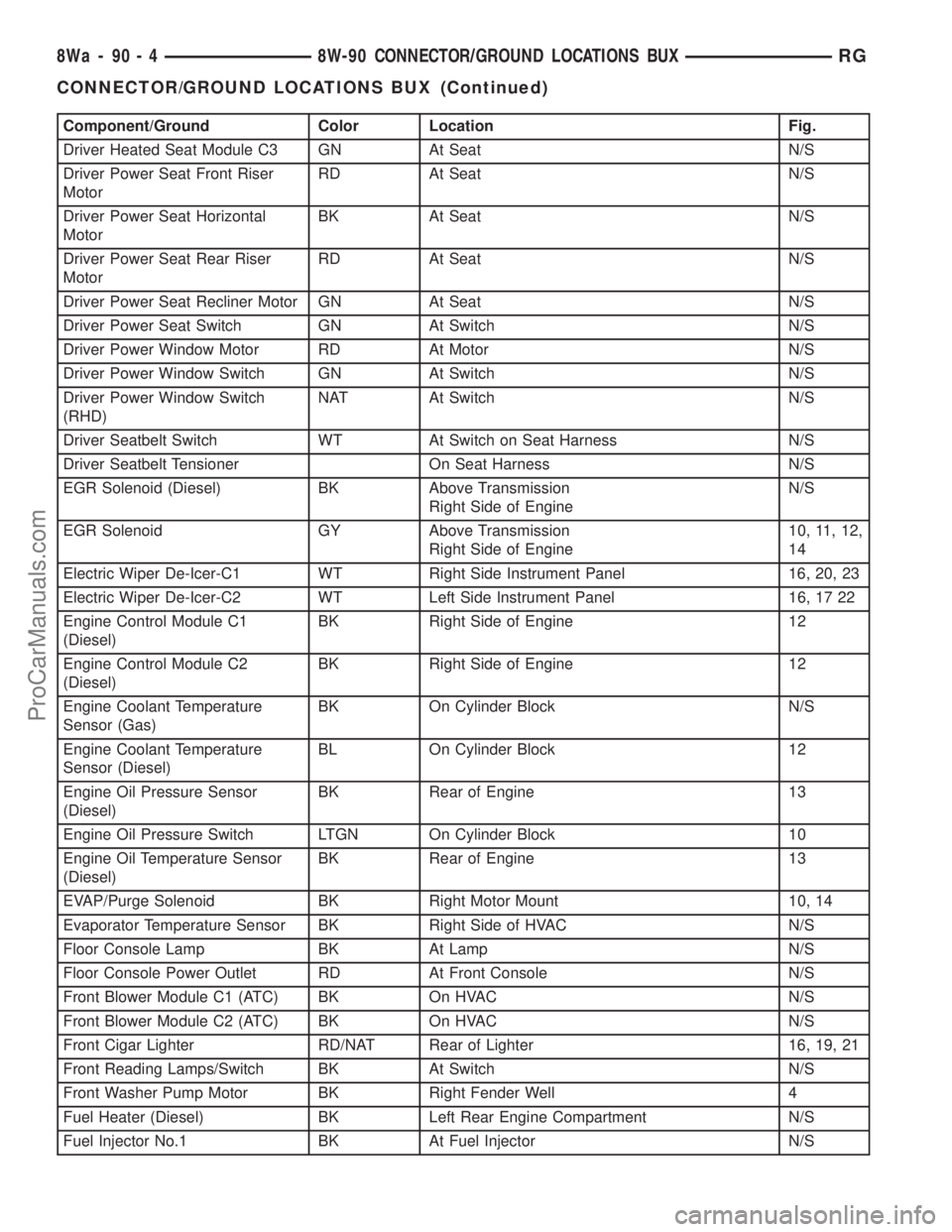
Component/Ground Color Location Fig.
Driver Heated Seat Module C3 GN At Seat N/S
Driver Power Seat Front Riser
MotorRD At Seat N/S
Driver Power Seat Horizontal
MotorBK At Seat N/S
Driver Power Seat Rear Riser
MotorRD At Seat N/S
Driver Power Seat Recliner Motor GN At Seat N/S
Driver Power Seat Switch GN At Switch N/S
Driver Power Window Motor RD At Motor N/S
Driver Power Window Switch GN At Switch N/S
Driver Power Window Switch
(RHD)NAT At Switch N/S
Driver Seatbelt Switch WT At Switch on Seat Harness N/S
Driver Seatbelt Tensioner On Seat Harness N/S
EGR Solenoid (Diesel) BK Above Transmission
Right Side of EngineN/S
EGR Solenoid GY Above Transmission
Right Side of Engine10, 11, 12,
14
Electric Wiper De-Icer-C1 WT Right Side Instrument Panel 16, 20, 23
Electric Wiper De-Icer-C2 WT Left Side Instrument Panel 16, 17 22
Engine Control Module C1
(Diesel)BK Right Side of Engine 12
Engine Control Module C2
(Diesel)BK Right Side of Engine 12
Engine Coolant Temperature
Sensor (Gas)BK On Cylinder Block N/S
Engine Coolant Temperature
Sensor (Diesel)BL On Cylinder Block 12
Engine Oil Pressure Sensor
(Diesel)BK Rear of Engine 13
Engine Oil Pressure Switch LTGN On Cylinder Block 10
Engine Oil Temperature Sensor
(Diesel)BK Rear of Engine 13
EVAP/Purge Solenoid BK Right Motor Mount 10, 14
Evaporator Temperature Sensor BK Right Side of HVAC N/S
Floor Console Lamp BK At Lamp N/S
Floor Console Power Outlet RD At Front Console N/S
Front Blower Module C1 (ATC) BK On HVAC N/S
Front Blower Module C2 (ATC) BK On HVAC N/S
Front Cigar Lighter RD/NAT Rear of Lighter 16, 19, 21
Front Reading Lamps/Switch BK At Switch N/S
Front Washer Pump Motor BK Right Fender Well 4
Fuel Heater (Diesel) BK Left Rear Engine Compartment N/S
Fuel Injector No.1 BK At Fuel Injector N/S
8Wa - 90 - 4 8W-90 CONNECTOR/GROUND LOCATIONS BUXRG
CONNECTOR/GROUND LOCATIONS BUX (Continued)
ProCarManuals.com
Page 1103 of 2321
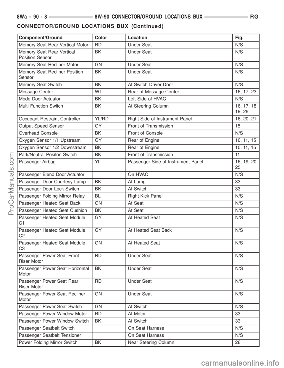
Component/Ground Color Location Fig.
Memory Seat Rear Vertical Motor RD Under Seat N/S
Memory Seat Rear Vertical
Position SensorBK Under Seat N/S
Memory Seat Recliner Motor GN Under Seat N/S
Memory Seat Recliner Position
SensorBK Under Seat N/S
Memory Seat Switch BK At Switch Driver Door N/S
Message Center WT Rear of Message Center 16, 17, 23
Mode Door Actuator BK Left Side of HVAC N/S
Multi Function Switch BK At Steering Column 16, 17, 18,
19, 26
Occupant Restraint Controller YL/RD Right Side of Instrument Panel 16, 20, 21
Output Speed Sensor GY Front of Transmission 15
Overhead Console BK Front of Console N/S
Oxygen Sensor 1/1 Upstream GY Rear of Engine 10, 11, 15
Oxygen Sensor 1/2 Downstream BK Rear of Engine 10, 11, 15
Park/Neutral Positon Switch BK Front of Transmission 11
Passenger Airbag YL Passenger Side of Instrument Panel 16, 19, 20,
25
Passenger Blend Door Actuator On HVAC N/S
Passenger Door Courtesy Lamp BK At Lamp 33
Passenger Door Lock Switch BK At Switch 33
Passenger Folding Mirror Relay BL Right Kick Panel N/S
Passenger Heated Seat Back GN At Seat N/S
Passenger Heated Seat Cushion BK At Seat N/S
Passenger Heated Seat Module
C1GY At Heated Seat N/S
Passenger Heated Seat Module
C2GY At Heated Seat Back N/S
Passenger Heated Seat Module
C3GN At Heated Seat N/S
Passenger Power Seat Front
Riser MotorRD Under Seat N/S
Passenger Power Seat Horizontal
MotorBK Under Seat N/S
Passenger Power Seat Rear
Riser MotorRD Under Seat N/S
Passenger Power Seat Recliner
MotorGN Under Seat N/S
Passenger Power Seat Switch GN At Switch N/S
Passenger Power Window Motor RD At Motor 33
Passenger Power Window Switch BK At Switch 33
Passenger Seatbelt Switch On Seat Harness N/S
Passenger Seatbelt Tensioner On Seat Harness N/S
Power Folding Mirror Switch BK Near Steering Column 26
8Wa - 90 - 8 8W-90 CONNECTOR/GROUND LOCATIONS BUXRG
CONNECTOR/GROUND LOCATIONS BUX (Continued)
ProCarManuals.com
Page 1104 of 2321
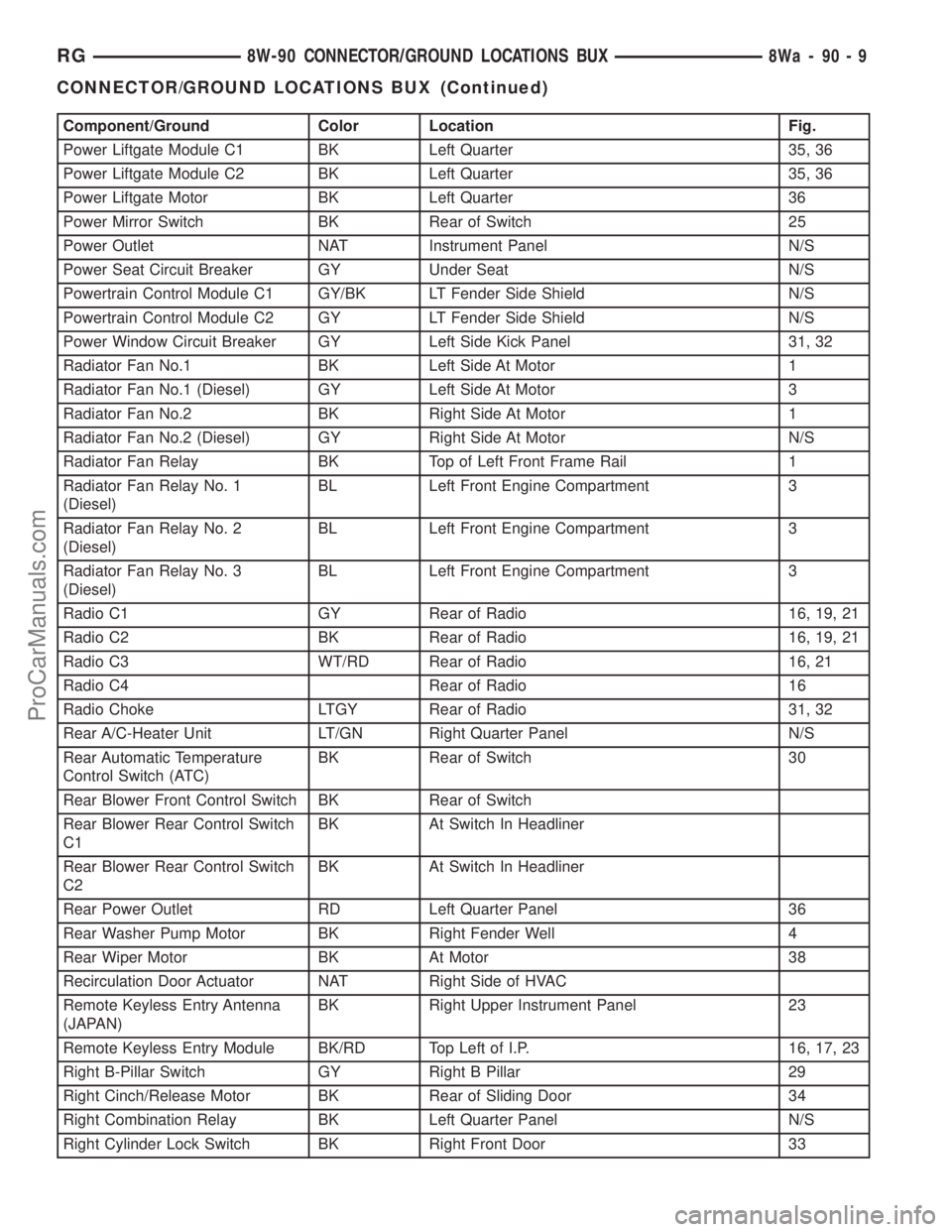
Component/Ground Color Location Fig.
Power Liftgate Module C1 BK Left Quarter 35, 36
Power Liftgate Module C2 BK Left Quarter 35, 36
Power Liftgate Motor BK Left Quarter 36
Power Mirror Switch BK Rear of Switch 25
Power Outlet NAT Instrument Panel N/S
Power Seat Circuit Breaker GY Under Seat N/S
Powertrain Control Module C1 GY/BK LT Fender Side Shield N/S
Powertrain Control Module C2 GY LT Fender Side Shield N/S
Power Window Circuit Breaker GY Left Side Kick Panel 31, 32
Radiator Fan No.1 BK Left Side At Motor 1
Radiator Fan No.1 (Diesel) GY Left Side At Motor 3
Radiator Fan No.2 BK Right Side At Motor 1
Radiator Fan No.2 (Diesel) GY Right Side At Motor N/S
Radiator Fan Relay BK Top of Left Front Frame Rail 1
Radiator Fan Relay No. 1
(Diesel)BL Left Front Engine Compartment 3
Radiator Fan Relay No. 2
(Diesel)BL Left Front Engine Compartment 3
Radiator Fan Relay No. 3
(Diesel)BL Left Front Engine Compartment 3
Radio C1 GY Rear of Radio 16, 19, 21
Radio C2 BK Rear of Radio 16, 19, 21
Radio C3 WT/RD Rear of Radio 16, 21
Radio C4 Rear of Radio 16
Radio Choke LTGY Rear of Radio 31, 32
Rear A/C-Heater Unit LT/GN Right Quarter Panel N/S
Rear Automatic Temperature
Control Switch (ATC)BK Rear of Switch 30
Rear Blower Front Control Switch BK Rear of Switch
Rear Blower Rear Control Switch
C1BK At Switch In Headliner
Rear Blower Rear Control Switch
C2BK At Switch In Headliner
Rear Power Outlet RD Left Quarter Panel 36
Rear Washer Pump Motor BK Right Fender Well 4
Rear Wiper Motor BK At Motor 38
Recirculation Door Actuator NAT Right Side of HVAC
Remote Keyless Entry Antenna
(JAPAN)BK Right Upper Instrument Panel 23
Remote Keyless Entry Module BK/RD Top Left of I.P. 16, 17, 23
Right B-Pillar Switch GY Right B Pillar 29
Right Cinch/Release Motor BK Rear of Sliding Door 34
Right Combination Relay BK Left Quarter Panel N/S
Right Cylinder Lock Switch BK Right Front Door 33
RG8W-90 CONNECTOR/GROUND LOCATIONS BUX8Wa-90-9
CONNECTOR/GROUND LOCATIONS BUX (Continued)
ProCarManuals.com
Page 1141 of 2321
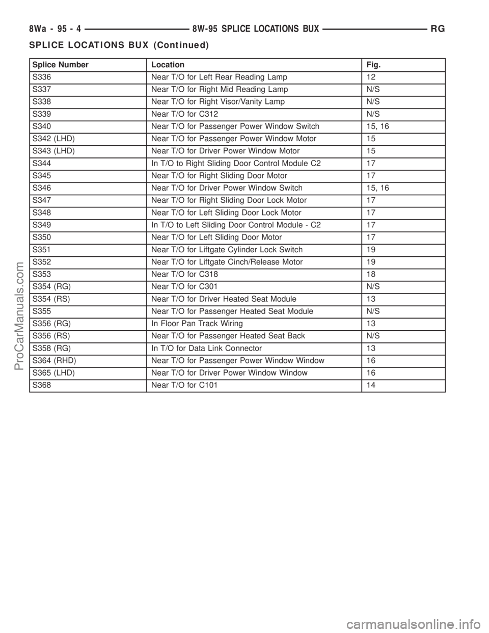
Splice Number Location Fig.
S336 Near T/O for Left Rear Reading Lamp 12
S337 Near T/O for Right Mid Reading Lamp N/S
S338 Near T/O for Right Visor/Vanity Lamp N/S
S339 Near T/O for C312 N/S
S340 Near T/O for Passenger Power Window Switch 15, 16
S342 (LHD) Near T/O for Passenger Power Window Motor 15
S343 (LHD) Near T/O for Driver Power Window Motor 15
S344 In T/O to Right Sliding Door Control Module C2 17
S345 Near T/O for Right Sliding Door Motor 17
S346 Near T/O for Driver Power Window Switch 15, 16
S347 Near T/O for Right Sliding Door Lock Motor 17
S348 Near T/O for Left Sliding Door Lock Motor 17
S349 In T/O to Left Sliding Door Control Module - C2 17
S350 Near T/O for Left Sliding Door Motor 17
S351 Near T/O for Liftgate Cylinder Lock Switch 19
S352 Near T/O for Liftgate Cinch/Release Motor 19
S353 Near T/O for C318 18
S354 (RG) Near T/O for C301 N/S
S354 (RS) Near T/O for Driver Heated Seat Module 13
S355 Near T/O for Passenger Heated Seat Module N/S
S356 (RG) In Floor Pan Track Wiring 13
S356 (RS) Near T/O for Passenger Heated Seat Back N/S
S358 (RG) In T/O for Data Link Connector 13
S364 (RHD) Near T/O for Passenger Power Window Window 16
S365 (LHD) Near T/O for Driver Power Window Window 16
S368 Near T/O for C101 14
8Wa - 95 - 4 8W-95 SPLICE LOCATIONS BUXRG
SPLICE LOCATIONS BUX (Continued)
ProCarManuals.com
Page 1916 of 2321
When the conditions causing a water leak have
been determined, simulate the conditions as closely
as possible.
²If a leak occurs with the vehicle parked in a
steady light rain, flood the leak area with an open-
ended garden hose.
²If a leak occurs while driving at highway speeds
in a steady rain, test the leak area with a reasonable
velocity stream or fan spray of water. Direct the
spray in a direction comparable to actual conditions.
²If a leak occurs when the vehicle is parked on an
incline, hoist the end or side of the vehicle to simu-
late this condition. This method can be used when
the leak occurs when the vehicle accelerates, stops or
turns. If the leak occurs on acceleration, hoist the
front of the vehicle. If the leak occurs when braking,
hoist the back of the vehicle. If the leak occurs on left
turns, hoist the left side of the vehicle. If the leak
occurs on right turns, hoist the right side of the vehi-
cle. For hoisting recommendations refer to Group 0,
Lubrication and Maintenance, General Information
section.
WATER LEAK DETECTION
To detect a water leak point-of-entry, do a water
test and watch for water tracks or droplets forming
on the inside of the vehicle. If necessary, remove inte-
rior trim covers or panels to gain visual access to the
leak area. If the hose cannot be positioned without
being held, have someone help do the water test.
Some water leaks must be tested for a considerable
length of time to become apparent. When a leak
appears, find the highest point of the water track or
drop. The highest point usually will show the point of
entry. After leak point has been found, repair the
leak and water test to verify that the leak has
stopped.
Locating the entry point of water that is leaking
into a cavity between panels can be difficult. The
trapped water may splash or run from the cavity,
often at a distance from the entry point. Most water
leaks of this type become apparent after accelerating,
stopping, turning, or when on an incline.
MIRROR INSPECTION METHOD
When a leak point area is visually obstructed, use
a suitable mirror to gain visual access. A mirror can
also be used to deflect light to a limited-access area
to assist in locating a leak point.
BRIGHT LIGHT LEAK TEST METHOD
Some water leaks in the luggage compartment can
be detected without water testing. Position the vehi-
cle in a brightly lit area. From inside the darkened
luggage compartment inspect around seals and body
seams. If necessary, have a helper direct a drop lightover the suspected leak areas around the luggage
compartment. If light is visible through a normally
sealed location, water could enter through the open-
ing.
PRESSURIZED LEAK TEST METHOD
When a water leak into the passenger compart-
ment cannot be detected by water testing, pressurize
the passenger compartment and soap test exterior of
the vehicle. To pressurize the passenger compart-
ment, close all doors and windows, start engine, and
set heater control to high blower in HEAT position. If
engine can not be started, connect a charger to the
battery to ensure adequate voltage to the blower.
With interior pressurized, apply dish detergent solu-
tion to suspected leak area on the exterior of the
vehicle. Apply detergent solution with spray device or
soft bristle brush. If soap bubbles occur at a body
seam, joint, seal or gasket, the leak entry point could
be at that location.
DIAGNOSIS AND TESTING - WIND NOISE
Wind noise is the result of most air leaks. Air leaks
can be caused by poor sealing, improper body compo-
nent alignment, body seam porosity, or missing plugs
in the engine compartment or door hinge pillar areas.
All body sealing points should be airtight in normal
driving conditions. Moving sealing surfaces will not
always seal airtight under all conditions. At times,
side glass or door seals will allow wind noise to be
noticed in the passenger compartment during high
cross winds. Over compensating on door or glass
adjustments to stop wind noise that occurs under
severe conditions can cause premature seal wear and
excessive closing or latching effort. After a repair pro-
cedure has been performed, test vehicle to verify
noise has stopped before returning vehicle to use.
Wind noise can also be caused by improperly fitted
exterior moldings or body ornamentation. Loose
moldings can flutter, creating a buzzing or chattering
noise. An open cavity or protruding edge can create a
whistling or howling noise. Inspect the exterior of the
vehicle to verify that these conditions do not exist.
VISUAL INSPECTION BEFORE TESTS
Verify that floor and body plugs are in place and
body components are aligned and sealed. If compo-
nent alignment or sealing is necessary, refer to the
appropriate section of this group for proper proce-
dures.
ROAD TESTING WIND NOISE
(1) Drive the vehicle to verify the general location
of the wind noise.
(2) Apply 50 mm (2 in.) masking tape in 150 mm
(6 in.) lengths along weatherstrips, weld seams or
RSBODY23-3
BODY (Continued)
ProCarManuals.com
Page 1923 of 2321
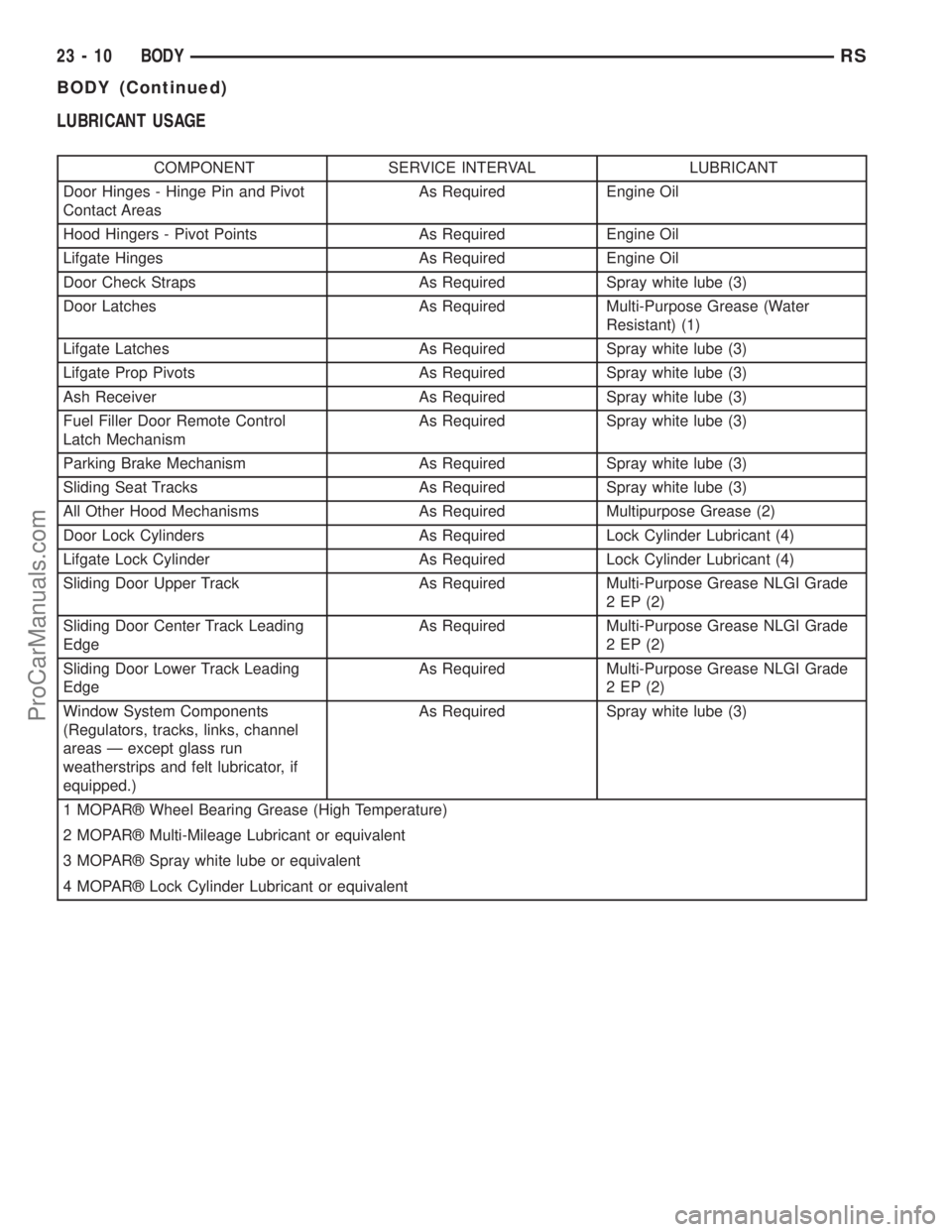
LUBRICANT USAGE
COMPONENT SERVICE INTERVAL LUBRICANT
Door Hinges - Hinge Pin and Pivot
Contact AreasAs Required Engine Oil
Hood Hingers - Pivot Points As Required Engine Oil
Lifgate Hinges As Required Engine Oil
Door Check Straps As Required Spray white lube (3)
Door Latches As Required Multi-Purpose Grease (Water
Resistant) (1)
Lifgate Latches As Required Spray white lube (3)
Lifgate Prop Pivots As Required Spray white lube (3)
Ash Receiver As Required Spray white lube (3)
Fuel Filler Door Remote Control
Latch MechanismAs Required Spray white lube (3)
Parking Brake Mechanism As Required Spray white lube (3)
Sliding Seat Tracks As Required Spray white lube (3)
All Other Hood Mechanisms As Required Multipurpose Grease (2)
Door Lock Cylinders As Required Lock Cylinder Lubricant (4)
Lifgate Lock Cylinder As Required Lock Cylinder Lubricant (4)
Sliding Door Upper Track As Required Multi-Purpose Grease NLGI Grade
2 EP (2)
Sliding Door Center Track Leading
EdgeAs Required Multi-Purpose Grease NLGI Grade
2 EP (2)
Sliding Door Lower Track Leading
EdgeAs Required Multi-Purpose Grease NLGI Grade
2 EP (2)
Window System Components
(Regulators, tracks, links, channel
areas Ð except glass run
weatherstrips and felt lubricator, if
equipped.)As Required Spray white lube (3)
1 MOPARž Wheel Bearing Grease (High Temperature)
2 MOPARž Multi-Mileage Lubricant or equivalent
3 MOPARž Spray white lube or equivalent
4 MOPARž Lock Cylinder Lubricant or equivalent
23 - 10 BODYRS
BODY (Continued)
ProCarManuals.com