belt DODGE TOWN AND COUNTRY 2001 Owner's Guide
[x] Cancel search | Manufacturer: DODGE, Model Year: 2001, Model line: TOWN AND COUNTRY, Model: DODGE TOWN AND COUNTRY 2001Pages: 2321, PDF Size: 68.09 MB
Page 312 of 2321
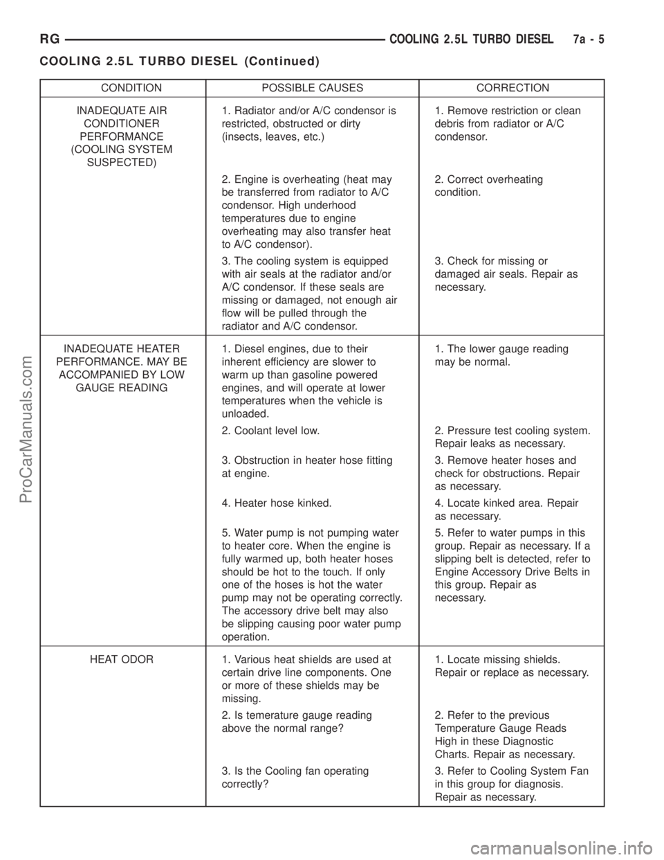
CONDITION POSSIBLE CAUSES CORRECTION
INADEQUATE AIR
CONDITIONER
PERFORMANCE
(COOLING SYSTEM
SUSPECTED)1. Radiator and/or A/C condensor is
restricted, obstructed or dirty
(insects, leaves, etc.)1. Remove restriction or clean
debris from radiator or A/C
condensor.
2. Engine is overheating (heat may
be transferred from radiator to A/C
condensor. High underhood
temperatures due to engine
overheating may also transfer heat
to A/C condensor).2. Correct overheating
condition.
3. The cooling system is equipped
with air seals at the radiator and/or
A/C condensor. If these seals are
missing or damaged, not enough air
flow will be pulled through the
radiator and A/C condensor.3. Check for missing or
damaged air seals. Repair as
necessary.
INADEQUATE HEATER
PERFORMANCE. MAY BE
ACCOMPANIED BY LOW
GAUGE READING1. Diesel engines, due to their
inherent efficiency are slower to
warm up than gasoline powered
engines, and will operate at lower
temperatures when the vehicle is
unloaded.1. The lower gauge reading
may be normal.
2. Coolant level low. 2. Pressure test cooling system.
Repair leaks as necessary.
3. Obstruction in heater hose fitting
at engine.3. Remove heater hoses and
check for obstructions. Repair
as necessary.
4. Heater hose kinked. 4. Locate kinked area. Repair
as necessary.
5. Water pump is not pumping water
to heater core. When the engine is
fully warmed up, both heater hoses
should be hot to the touch. If only
one of the hoses is hot the water
pump may not be operating correctly.
The accessory drive belt may also
be slipping causing poor water pump
operation.5. Refer to water pumps in this
group. Repair as necessary. If a
slipping belt is detected, refer to
Engine Accessory Drive Belts in
this group. Repair as
necessary.
HEAT ODOR 1. Various heat shields are used at
certain drive line components. One
or more of these shields may be
missing.1. Locate missing shields.
Repair or replace as necessary.
2. Is temerature gauge reading
above the normal range?2. Refer to the previous
Temperature Gauge Reads
High in these Diagnostic
Charts. Repair as necessary.
3. Is the Cooling fan operating
correctly?3. Refer to Cooling System Fan
in this group for diagnosis.
Repair as necessary.
RGCOOLING 2.5L TURBO DIESEL7a-5
COOLING 2.5L TURBO DIESEL (Continued)
ProCarManuals.com
Page 315 of 2321
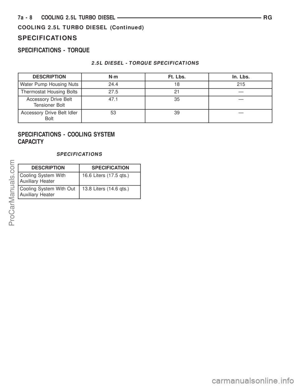
SPECIFICATIONS
SPECIFICATIONS - TORQUE
2.5L DIESEL - TORQUE SPECIFICATIONS
DESCRIPTION N´m Ft. Lbs. In. Lbs.
Water Pump Housing Nuts 24.4 18 215
Thermostat Housing Bolts 27.5 21 Ð
Accessory Drive Belt
Tensioner Bolt47.1 35 Ð
Accessory Drive Belt Idler
Bolt53 39 Ð
SPECIFICATIONS - COOLING SYSTEM
CAPACITY
SPECIFICATIONS
DESCRIPTION SPECIFICATION
Cooling System With
Auxiliary Heater16.6 Liters (17.5 qts.)
Cooling System With Out
Auxiliary Heater13.8 Liters (14.6 qts.)
7a - 8 COOLING 2.5L TURBO DIESELRG
COOLING 2.5L TURBO DIESEL (Continued)
ProCarManuals.com
Page 316 of 2321
ACCESSORY DRIVE
TABLE OF CONTENTS
page page
ACCESSORY DRIVE
SPECIFICATIONS.........................9
BELT TENSIONER
REMOVAL...............................9
INSTALLATION............................9
IDLER PULLEY
REMOVAL..............................10
INSTALLATION...........................10DRIVE BELTS
DESCRIPTION...........................10
OPERATION.............................10
DIAGNOSIS AND TESTING.................11
ACCESSORY DRIVE BELT................11
REMOVAL..............................11
INSTALLATION...........................11
ACCESSORY DRIVE
SPECIFICATIONS
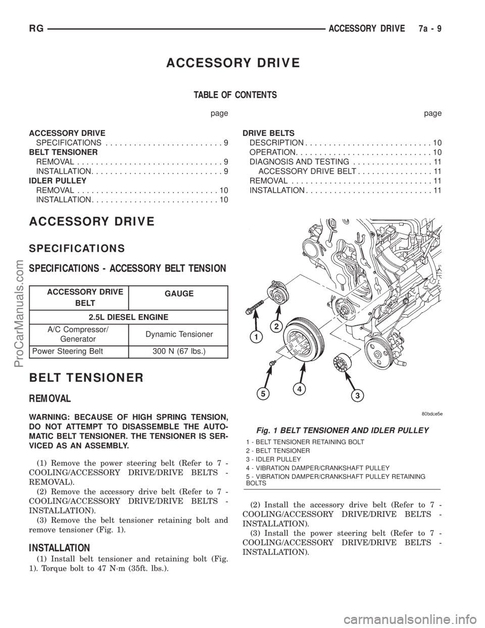
SPECIFICATIONS - ACCESSORY BELT TENSION
ACCESSORY DRIVE
BELTGAUGE
2.5L DIESEL ENGINE
A/C Compressor/
GeneratorDynamic Tensioner
Power Steering Belt 300 N (67 lbs.)
BELT TENSIONER
REMOVAL
WARNING: BECAUSE OF HIGH SPRING TENSION,
DO NOT ATTEMPT TO DISASSEMBLE THE AUTO-
MATIC BELT TENSIONER. THE TENSIONER IS SER-
VICED AS AN ASSEMBLY.
(1) Remove the power steering belt (Refer to 7 -
COOLING/ACCESSORY DRIVE/DRIVE BELTS -
REMOVAL).
(2) Remove the accessory drive belt (Refer to 7 -
COOLING/ACCESSORY DRIVE/DRIVE BELTS -
INSTALLATION).
(3) Remove the belt tensioner retaining bolt and
remove tensioner (Fig. 1).
INSTALLATION
(1) Install belt tensioner and retaining bolt (Fig.
1). Torque bolt to 47 N´m (35ft. lbs.).(2) Install the accessory drive belt (Refer to 7 -
COOLING/ACCESSORY DRIVE/DRIVE BELTS -
INSTALLATION).
(3) Install the power steering belt (Refer to 7 -
COOLING/ACCESSORY DRIVE/DRIVE BELTS -
INSTALLATION).
Fig. 1 BELT TENSIONER AND IDLER PULLEY
1 - BELT TENSIONER RETAINING BOLT
2 - BELT TENSIONER
3 - IDLER PULLEY
4 - VIBRATION DAMPER/CRANKSHAFT PULLEY
5 - VIBRATION DAMPER/CRANKSHAFT PULLEY RETAINING
BOLTS
RGACCESSORY DRIVE7a-9
ProCarManuals.com
Page 317 of 2321
IDLER PULLEY
REMOVAL
(1) Remove the accessory drive belt (Refer to 7 -
COOLING/ACCESSORY DRIVE/DRIVE BELTS -
REMOVAL).
CAUTION: IDLER PULLEY RETAINING BOLT HAS
LEFT HAND THREAD
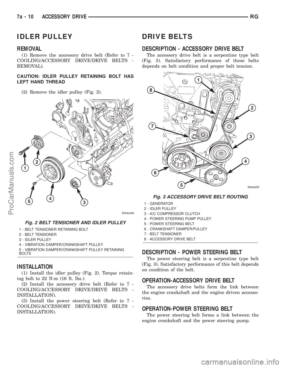
(2) Remove the idler pulley (Fig. 2).
INSTALLATION
(1) Install the idler pulley (Fig. 2). Torque retain-
ing bolt to 22 N´m (16 ft. lbs.).
(2) Install the accessory drive belt (Refer to 7 -
COOLING/ACCESSORY DRIVE/DRIVE BELTS -
INSTALLATION).
(3) Install the power steering belt (Refer to 7 -
COOLING/ACCESSORY DRIVE/DRIVE BELTS -
INSTALLATION).
DRIVE BELTS
DESCRIPTION - ACCESSORY DRIVE BELT
The accessory drive belt is a serpentine type belt
(Fig. 3). Satisfactory performance of these belts
depends on belt condition and proper belt tension.
DESCRIPTION - POWER STEERING BELT
The power steering belt is a serpentine type belt
(Fig. 3). Satisfactory performance of this belt depends
on condition of the belt.
OPERATION-ACCESSORY DRIVE BELT
The accessory drive belts form the link between
the engine crankshaft and the engine driven accesso-
ries.
OPERATION-POWER STEERING BELT
The power steering belt forms a link between the
engine crankshaft and the power steering pump.
Fig. 2 BELT TENSIONER AND IDLER PULLEY
1 - BELT TENSIONER RETAINING BOLT
2 - BELT TENSIONER
3 - IDLER PULLEY
4 - VIBRATION DAMPER/CRANKSHAFT PULLEY
5 - VIBRATION DAMPER/CRANKSHAFT PULLEY RETAINING
BOLTS
Fig. 3 ACCESSORY DRIVE BELT ROUTING
1 - GENERATOR
2 - IDLER PULLEY
3 - A/C COMPRESSOR CLUTCH
4 - POWER STEERING PUMP PULLEY
5 - POWER STEERING BELT
6 - CRANKSHAFT DAMPER/PULLEY
7 - BELT TENSIONER
8 - ACCESSORY DRIVE BELT
7a - 10 ACCESSORY DRIVERG
ProCarManuals.com
Page 318 of 2321
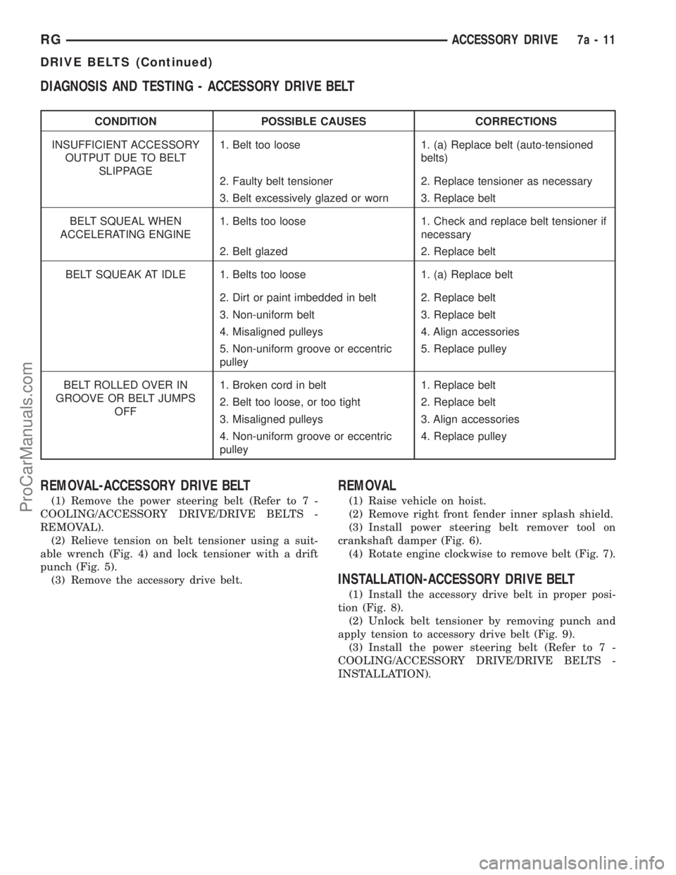
DIAGNOSIS AND TESTING - ACCESSORY DRIVE BELT
CONDITION POSSIBLE CAUSES CORRECTIONS
INSUFFICIENT ACCESSORY
OUTPUT DUE TO BELT
SLIPPAGE1. Belt too loose 1. (a) Replace belt (auto-tensioned
belts)
2. Faulty belt tensioner 2. Replace tensioner as necessary
3. Belt excessively glazed or worn 3. Replace belt
BELT SQUEAL WHEN
ACCELERATING ENGINE1. Belts too loose 1. Check and replace belt tensioner if
necessary
2. Belt glazed 2. Replace belt
BELT SQUEAK AT IDLE 1. Belts too loose 1. (a) Replace belt
2. Dirt or paint imbedded in belt 2. Replace belt
3. Non-uniform belt 3. Replace belt
4. Misaligned pulleys 4. Align accessories
5. Non-uniform groove or eccentric
pulley5. Replace pulley
BELT ROLLED OVER IN
GROOVE OR BELT JUMPS
OFF1. Broken cord in belt 1. Replace belt
2. Belt too loose, or too tight 2. Replace belt
3. Misaligned pulleys 3. Align accessories
4. Non-uniform groove or eccentric
pulley4. Replace pulley
REMOVAL-ACCESSORY DRIVE BELT
(1) Remove the power steering belt (Refer to 7 -
COOLING/ACCESSORY DRIVE/DRIVE BELTS -
REMOVAL).
(2) Relieve tension on belt tensioner using a suit-
able wrench (Fig. 4) and lock tensioner with a drift
punch (Fig. 5).
(3) Remove the accessory drive belt.
REMOVAL
(1) Raise vehicle on hoist.
(2) Remove right front fender inner splash shield.
(3) Install power steering belt remover tool on
crankshaft damper (Fig. 6).
(4) Rotate engine clockwise to remove belt (Fig. 7).
INSTALLATION-ACCESSORY DRIVE BELT
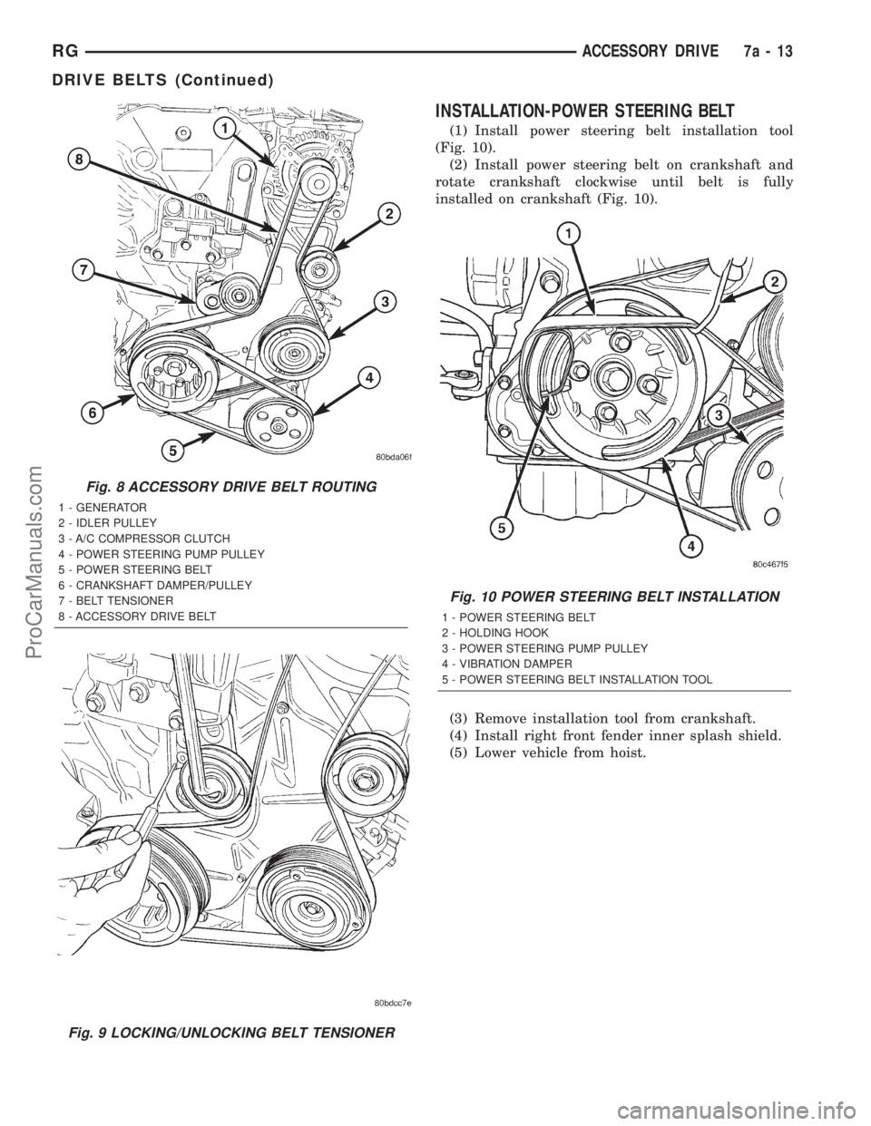
(1) Install the accessory drive belt in proper posi-
tion (Fig. 8).
(2) Unlock belt tensioner by removing punch and
apply tension to accessory drive belt (Fig. 9).
(3) Install the power steering belt (Refer to 7 -
COOLING/ACCESSORY DRIVE/DRIVE BELTS -
INSTALLATION).
RGACCESSORY DRIVE7a-11
DRIVE BELTS (Continued)
ProCarManuals.com
Page 319 of 2321
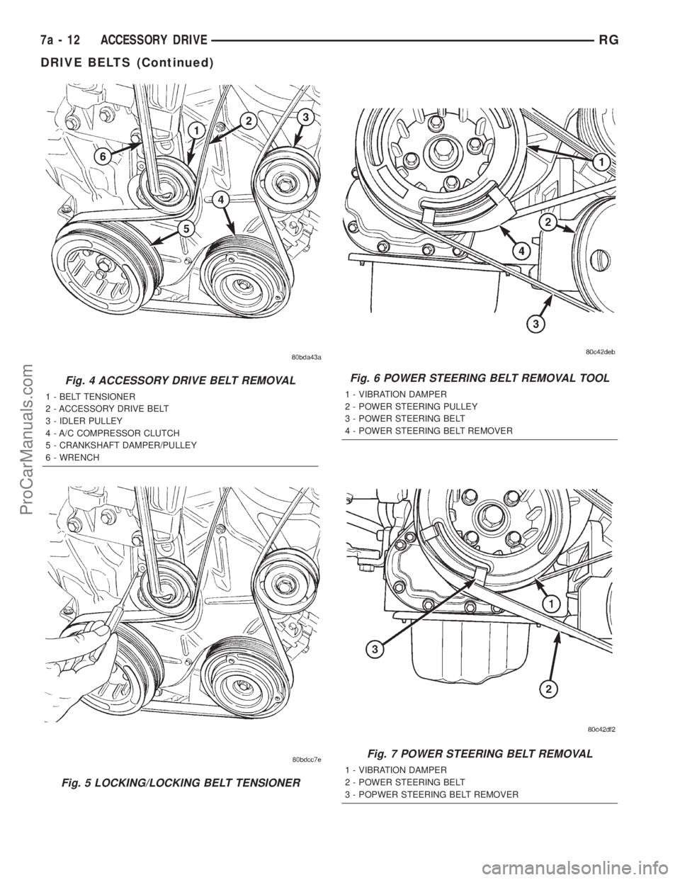
Fig. 4 ACCESSORY DRIVE BELT REMOVAL
1 - BELT TENSIONER
2 - ACCESSORY DRIVE BELT
3 - IDLER PULLEY
4 - A/C COMPRESSOR CLUTCH
5 - CRANKSHAFT DAMPER/PULLEY
6 - WRENCH
Fig. 5 LOCKING/LOCKING BELT TENSIONER
Fig. 6 POWER STEERING BELT REMOVAL TOOL
1 - VIBRATION DAMPER
2 - POWER STEERING PULLEY
3 - POWER STEERING BELT
4 - POWER STEERING BELT REMOVER
Fig. 7 POWER STEERING BELT REMOVAL
1 - VIBRATION DAMPER
2 - POWER STEERING BELT
3 - POPWER STEERING BELT REMOVER
7a - 12 ACCESSORY DRIVERG
DRIVE BELTS (Continued)
ProCarManuals.com
Page 320 of 2321
INSTALLATION-POWER STEERING BELT
(1) Install power steering belt installation tool
(Fig. 10).
(2) Install power steering belt on crankshaft and
rotate crankshaft clockwise until belt is fully
installed on crankshaft (Fig. 10).
(3) Remove installation tool from crankshaft.
(4) Install right front fender inner splash shield.
(5) Lower vehicle from hoist.
Fig. 8 ACCESSORY DRIVE BELT ROUTING
1 - GENERATOR
2 - IDLER PULLEY
3 - A/C COMPRESSOR CLUTCH
4 - POWER STEERING PUMP PULLEY
5 - POWER STEERING BELT
6 - CRANKSHAFT DAMPER/PULLEY
7 - BELT TENSIONER
8 - ACCESSORY DRIVE BELT
Fig. 9 LOCKING/UNLOCKING BELT TENSIONER
Fig. 10 POWER STEERING BELT INSTALLATION
1 - POWER STEERING BELT
2 - HOLDING HOOK
3 - POWER STEERING PUMP PULLEY
4 - VIBRATION DAMPER
5 - POWER STEERING BELT INSTALLATION TOOL
RGACCESSORY DRIVE7a-13
DRIVE BELTS (Continued)
ProCarManuals.com
Page 323 of 2321
STANDARD PROCEDURE - COOLANT LEVEL
CHECK
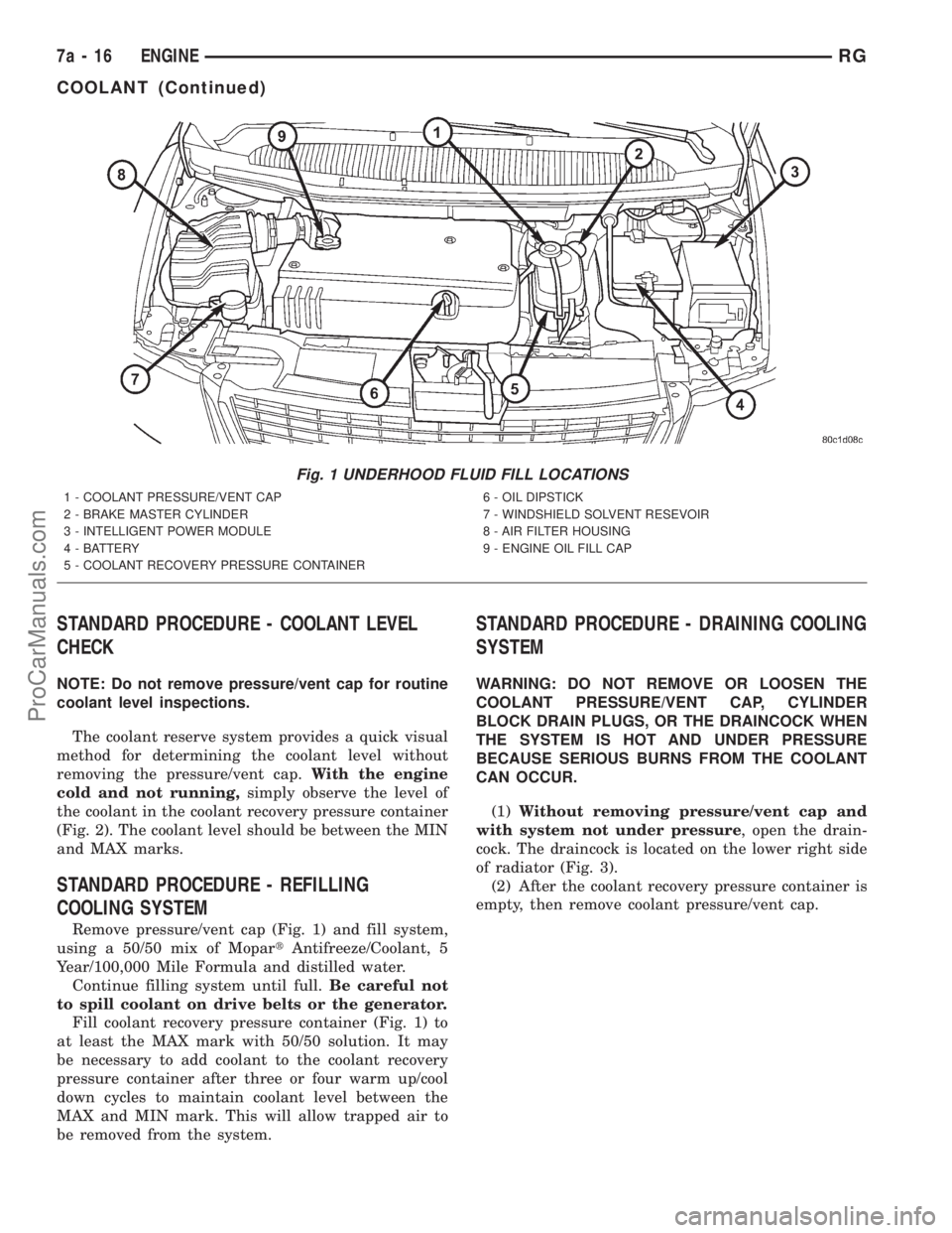
NOTE: Do not remove pressure/vent cap for routine
coolant level inspections.
The coolant reserve system provides a quick visual
method for determining the coolant level without
removing the pressure/vent cap.With the engine
cold and not running,simply observe the level of
the coolant in the coolant recovery pressure container
(Fig. 2). The coolant level should be between the MIN
and MAX marks.
STANDARD PROCEDURE - REFILLING
COOLING SYSTEM
Remove pressure/vent cap (Fig. 1) and fill system,
using a 50/50 mix of MopartAntifreeze/Coolant, 5
Year/100,000 Mile Formula and distilled water.
Continue filling system until full.Be careful not
to spill coolant on drive belts or the generator.
Fill coolant recovery pressure container (Fig. 1) to
at least the MAX mark with 50/50 solution. It may
be necessary to add coolant to the coolant recovery
pressure container after three or four warm up/cool
down cycles to maintain coolant level between the
MAX and MIN mark. This will allow trapped air to
be removed from the system.
STANDARD PROCEDURE - DRAINING COOLING
SYSTEM
WARNING: DO NOT REMOVE OR LOOSEN THE
COOLANT PRESSURE/VENT CAP, CYLINDER
BLOCK DRAIN PLUGS, OR THE DRAINCOCK WHEN
THE SYSTEM IS HOT AND UNDER PRESSURE
BECAUSE SERIOUS BURNS FROM THE COOLANT
CAN OCCUR.
(1)Without removing pressure/vent cap and
with system not under pressure, open the drain-
cock. The draincock is located on the lower right side
of radiator (Fig. 3).
(2) After the coolant recovery pressure container is
empty, then remove coolant pressure/vent cap.
Fig. 1 UNDERHOOD FLUID FILL LOCATIONS
1 - COOLANT PRESSURE/VENT CAP
2 - BRAKE MASTER CYLINDER
3 - INTELLIGENT POWER MODULE
4 - BATTERY
5 - COOLANT RECOVERY PRESSURE CONTAINER6 - OIL DIPSTICK
7 - WINDSHIELD SOLVENT RESEVOIR
8 - AIR FILTER HOUSING
9 - ENGINE OIL FILL CAP
7a - 16 ENGINERG
COOLANT (Continued)
ProCarManuals.com
Page 329 of 2321
RADIATOR DRAINCOCK
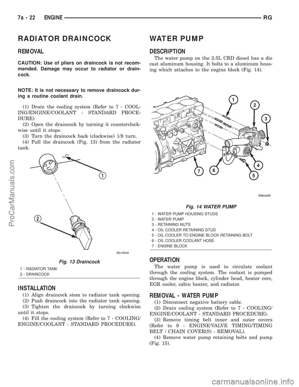
REMOVAL
CAUTION: Use of pliers on draincock is not recom-
mended. Damage may occur to radiator or drain-
cock.
NOTE: It is not necessary to remove draincock dur-
ing a routine coolant drain.
(1) Drain the cooling system (Refer to 7 - COOL-
ING/ENGINE/COOLANT - STANDARD PROCE-
DURE).
(2) Open the draincock by turning it counterclock-
wise until it stops.
(3) Turn the draincock back (clockwise) 1/8 turn.
(4) Pull the draincock (Fig. 13) from the radiator
tank.
INSTALLATION
(1) Align draincock stem to radiator tank opening.
(2) Push draincock into the radiator tank opening.
(3) Tighten the draincock by turning clockwise
until it stops.
(4) Fill the cooling system (Refer to 7 - COOLING/
ENGINE/COOLANT - STANDARD PROCEDURE).
WATER PUMP
DESCRIPTION
The water pump on the 2.5L CRD diesel has a die
cast aluminum housing. It bolts to a aluminum hous-
ing which attaches to the engine block (Fig. 14).
OPERATION
The water pump is used to circulate coolant
through the cooling system. The coolant is pumped
through the engine block, cylinder head, heater core,
EGR cooler, cabin heater, and radiator.
REMOVAL - WATER PUMP
(1) Disconnect negative battery cable.
(2) Drain cooling system (Refer to 7 - COOLING/
ENGINE/COOLANT - STANDARD PROCEDURE).
(3) Remove timing belt inner and outer covers
(Refer to 9 - ENGINE/VALVE TIMING/TIMING
BELT / CHAIN COVER(S) - REMOVAL).
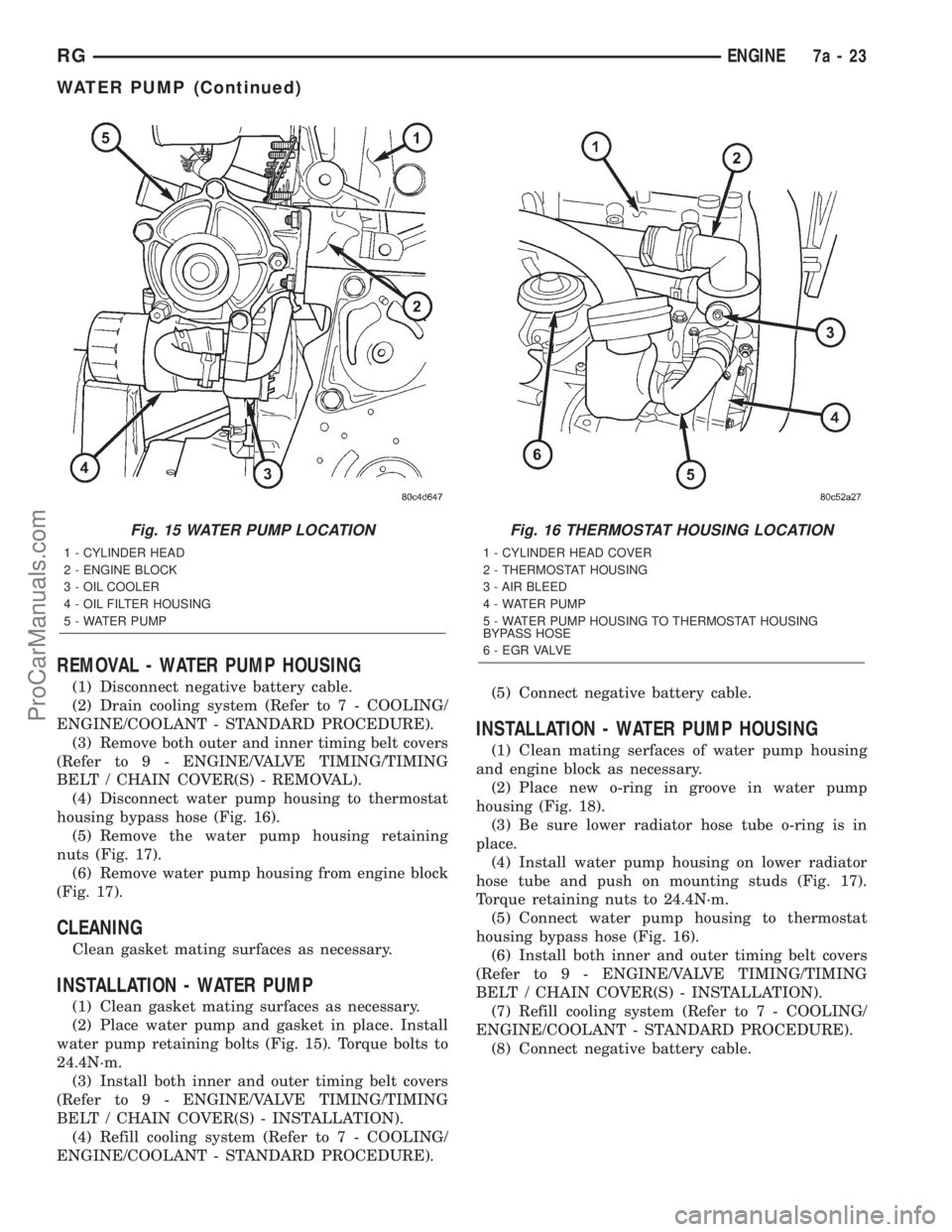
(4) Remove water pump retaining bolts and pump
(Fig. 15).
Fig. 13 Draincock
1 - RADIATOR TANK
2 - DRAINCOCK
Fig. 14 WATER PUMP
1 - WATER PUMP HOUSING STUDS
2 - WATER PUMP
3 - RETAINING NUTS
4 - OIL COOLER RETAINING STUD
5 - OIL COOLER TO ENGINE BLOCK RETAINING BOLT
6 - OIL COOLER COOLANT HOSE
7 - ENGINE BLOCK
7a - 22 ENGINERG
ProCarManuals.com
Page 330 of 2321
REMOVAL - WATER PUMP HOUSING
(1) Disconnect negative battery cable.
(2) Drain cooling system (Refer to 7 - COOLING/
ENGINE/COOLANT - STANDARD PROCEDURE).
(3) Remove both outer and inner timing belt covers
(Refer to 9 - ENGINE/VALVE TIMING/TIMING
BELT / CHAIN COVER(S) - REMOVAL).
(4) Disconnect water pump housing to thermostat
housing bypass hose (Fig. 16).
(5) Remove the water pump housing retaining
nuts (Fig. 17).
(6) Remove water pump housing from engine block
(Fig. 17).
CLEANING
Clean gasket mating surfaces as necessary.
INSTALLATION - WATER PUMP
(1) Clean gasket mating surfaces as necessary.
(2) Place water pump and gasket in place. Install
water pump retaining bolts (Fig. 15). Torque bolts to
24.4N´m.
(3) Install both inner and outer timing belt covers
(Refer to 9 - ENGINE/VALVE TIMING/TIMING
BELT / CHAIN COVER(S) - INSTALLATION).
(4) Refill cooling system (Refer to 7 - COOLING/
ENGINE/COOLANT - STANDARD PROCEDURE).(5) Connect negative battery cable.
INSTALLATION - WATER PUMP HOUSING
(1) Clean mating serfaces of water pump housing
and engine block as necessary.
(2) Place new o-ring in groove in water pump
housing (Fig. 18).
(3) Be sure lower radiator hose tube o-ring is in
place.
(4) Install water pump housing on lower radiator
hose tube and push on mounting studs (Fig. 17).
Torque retaining nuts to 24.4N´m.
(5) Connect water pump housing to thermostat
housing bypass hose (Fig. 16).
(6) Install both inner and outer timing belt covers
(Refer to 9 - ENGINE/VALVE TIMING/TIMING
BELT / CHAIN COVER(S) - INSTALLATION).
(7) Refill cooling system (Refer to 7 - COOLING/
ENGINE/COOLANT - STANDARD PROCEDURE).
(8) Connect negative battery cable.
Fig. 15 WATER PUMP LOCATION
1 - CYLINDER HEAD
2 - ENGINE BLOCK
3 - OIL COOLER
4 - OIL FILTER HOUSING
5 - WATER PUMP
Fig. 16 THERMOSTAT HOUSING LOCATION
1 - CYLINDER HEAD COVER
2 - THERMOSTAT HOUSING
3 - AIR BLEED
4 - WATER PUMP
5 - WATER PUMP HOUSING TO THERMOSTAT HOUSING
BYPASS HOSE
6 - E G R VA LV E
RGENGINE7a-23
WATER PUMP (Continued)
ProCarManuals.com