transmission DODGE TOWN AND COUNTRY 2001 Workshop Manual
[x] Cancel search | Manufacturer: DODGE, Model Year: 2001, Model line: TOWN AND COUNTRY, Model: DODGE TOWN AND COUNTRY 2001Pages: 2321, PDF Size: 68.09 MB
Page 305 of 2321
TRANS COOLER
DESCRIPTION
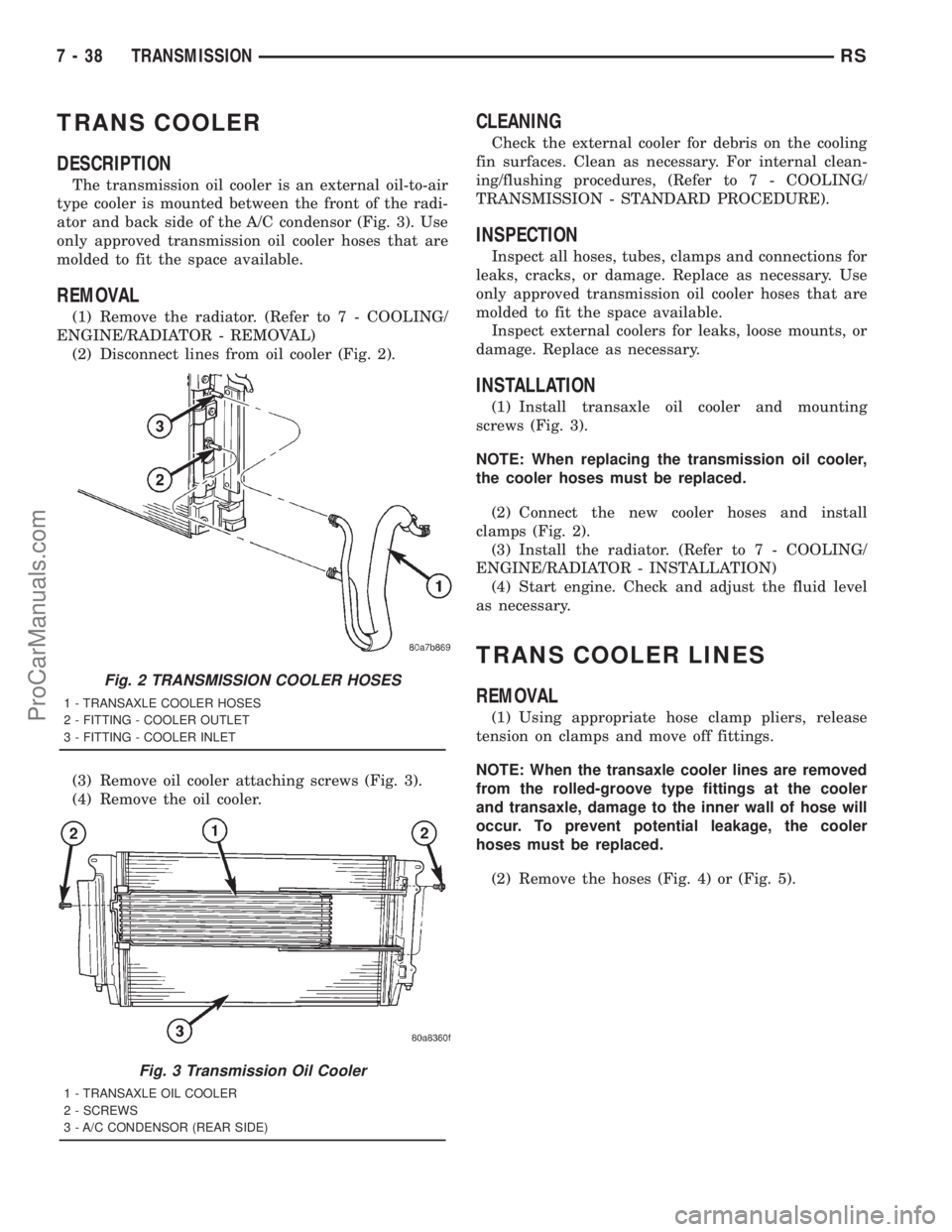
The transmission oil cooler is an external oil-to-air
type cooler is mounted between the front of the radi-
ator and back side of the A/C condensor (Fig. 3). Use
only approved transmission oil cooler hoses that are
molded to fit the space available.
REMOVAL
(1) Remove the radiator. (Refer to 7 - COOLING/
ENGINE/RADIATOR - REMOVAL)
(2) Disconnect lines from oil cooler (Fig. 2).
(3) Remove oil cooler attaching screws (Fig. 3).
(4) Remove the oil cooler.
CLEANING
Check the external cooler for debris on the cooling
fin surfaces. Clean as necessary. For internal clean-
ing/flushing procedures, (Refer to 7 - COOLING/
TRANSMISSION - STANDARD PROCEDURE).
INSPECTION
Inspect all hoses, tubes, clamps and connections for
leaks, cracks, or damage. Replace as necessary. Use
only approved transmission oil cooler hoses that are
molded to fit the space available.
Inspect external coolers for leaks, loose mounts, or
damage. Replace as necessary.
INSTALLATION
(1) Install transaxle oil cooler and mounting
screws (Fig. 3).
NOTE: When replacing the transmission oil cooler,
the cooler hoses must be replaced.
(2) Connect the new cooler hoses and install
clamps (Fig. 2).
(3) Install the radiator. (Refer to 7 - COOLING/
ENGINE/RADIATOR - INSTALLATION)
(4) Start engine. Check and adjust the fluid level
as necessary.
TRANS COOLER LINES
REMOVAL
(1) Using appropriate hose clamp pliers, release
tension on clamps and move off fittings.
NOTE: When the transaxle cooler lines are removed
from the rolled-groove type fittings at the cooler
and transaxle, damage to the inner wall of hose will
occur. To prevent potential leakage, the cooler
hoses must be replaced.
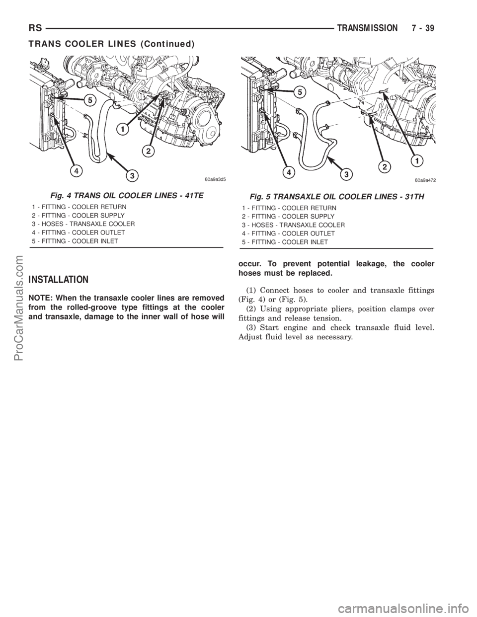
(2) Remove the hoses (Fig. 4) or (Fig. 5).
Fig. 2 TRANSMISSION COOLER HOSES
1 - TRANSAXLE COOLER HOSES
2 - FITTING - COOLER OUTLET
3 - FITTING - COOLER INLET
Fig. 3 Transmission Oil Cooler
1 - TRANSAXLE OIL COOLER
2 - SCREWS
3 - A/C CONDENSOR (REAR SIDE)
7 - 38 TRANSMISSIONRS
ProCarManuals.com
Page 306 of 2321
INSTALLATION
NOTE: When the transaxle cooler lines are removed
from the rolled-groove type fittings at the cooler
and transaxle, damage to the inner wall of hose willoccur. To prevent potential leakage, the cooler
hoses must be replaced.
(1) Connect hoses to cooler and transaxle fittings
(Fig. 4) or (Fig. 5).
(2) Using appropriate pliers, position clamps over
fittings and release tension.
(3) Start engine and check transaxle fluid level.
Adjust fluid level as necessary.
Fig. 4 TRANS OIL COOLER LINES - 41TE
1 - FITTING - COOLER RETURN
2 - FITTING - COOLER SUPPLY
3 - HOSES - TRANSAXLE COOLER
4 - FITTING - COOLER OUTLET
5 - FITTING - COOLER INLET
Fig. 5 TRANSAXLE OIL COOLER LINES - 31TH
1 - FITTING - COOLER RETURN
2 - FITTING - COOLER SUPPLY
3 - HOSES - TRANSAXLE COOLER
4 - FITTING - COOLER OUTLET
5 - FITTING - COOLER INLET
RSTRANSMISSION7-39
TRANS COOLER LINES (Continued)
ProCarManuals.com
Page 358 of 2321
ELECTRONIC CONTROL MODULES
TABLE OF CONTENTS
page page
ELECTRONIC CONTROL MODULES
STANDARD PROCEDURE...................1
PCM/SKIM PROGRAMMING................1
BODY CONTROL MODULE
DESCRIPTION............................2
OPERATION.............................3
REMOVAL...............................3
INSTALLATION............................3
CONTROLLER ANTILOCK BRAKE
DESCRIPTION............................3
OPERATION.............................3
REMOVAL...............................4
INSTALLATION............................4
DATA LINK CONNECTOR
DESCRIPTION............................5
OPERATION.............................5
FRONT CONTROL MODULE
DESCRIPTION............................5
OPERATION.............................5
DIAGNOSIS AND TESTING..................6
FRONT CONTROL MODULE...............6
REMOVAL...............................6
INSTALLATION............................6
MEMORY HEATED SEAT/MIRROR MODULE
REMOVAL...............................7
INSTALLATION............................7
POWER LIFTGATE MODULE
DESCRIPTION............................7
OPERATION.............................7REMOVAL...............................7
INSTALLATION............................8
POWERTRAIN CONTROL MODULE
DESCRIPTION............................8
OPERATION.............................19
STANDARD PROCEDURE..................21
OBTAINING DIAGNOSTIC TROUBLE
CODES...............................21
REMOVAL..............................22
INSTALLATION...........................22
SENTRY KEY IMMOBILIZER MODULE
DESCRIPTION...........................22
OPERATION.............................23
REMOVAL..............................23
INSTALLATION...........................23
SLIDING DOOR CONTROL MODULE
DESCRIPTION...........................23
OPERATION.............................24
REMOVAL..............................24
INSTALLATION...........................24
TRANSMISSION CONTROL MODULE
DESCRIPTION...........................24
OPERATION.............................24
STANDARD PROCEDURE..................27
PINION FACTOR PROCEDURE............27
QUICK LEARN PROCEDURE..............27
TCC BREAK-IN VIEW/RESET PROCEDURE. . . 28
REMOVAL..............................28
INSTALLATION...........................29
ELECTRONIC CONTROL
MODULES
STANDARD PROCEDURE - PCM/SKIM
PROGRAMMING
NOTE: Before replacing the PCM for a failed driver,
control circuit or ground circuit, be sure to check
the related component/circuit integrity for failures
not detected due to a double fault in the circuit.
Most PCM driver/control circuit failures are caused
by internal component failures (i.e. relay and sole-
noids) and shorted circuits (i.e. pull-ups, drivers
and switched circuits). These failures are difficult to
detect when a double fault has occurred and only
one DTC has set.When a PCM (SBEC) and the SKIM are replaced
at the same time perform the following steps in
order:
(1) Program the new PCM (SBEC)
(2) Program the new SKIM
(3) Replace all ignition keys and program them to
the new SKIM.
PROGRAMMING THE PCM (SBEC)
The SKIS Secret Key is an ID code that is unique
to each SKIM. This code is programmed and stored
in the SKIM, PCM and transponder chip (ignition
keys). When replacing the PCM it is necessary to
program the secret key into the new PCM using the
DRB III. Perform the following steps to program the
secret key into the PCM.
RSELECTRONIC CONTROL MODULES8E-1
ProCarManuals.com
Page 359 of 2321
(1) Turn the ignition switch on (transmission in
park/neutral).
(2) Use the DRB III and select THEFT ALARM,
SKIM then MISCELLANEOUS.
(3) Select PCM REPLACED (GAS ENGINE).
(4) Enter secured access mode by entering the
vehicle four-digit PIN.
(5) Select ENTER to update PCM VIN.
NOTE: If three attempts are made to enter secure
access mode using an incorrect PIN, secured
access mode will be locked out for one hour. To
exit this lockout mode, turn the ignition to the RUN
position for one hour then enter the correct PIN.
(Ensure all accessories are turned off. Also monitor
the battery state and connect a battery charger if
necessary).
(6) Press ENTER to transfer the secret key (the
SKIM will send the secret key to the PCM).
(7) Press Page Back to get to the Select System
menu and select ENGINE, MISCELLANEOUS, and
SRI MEMORY CHECK.
(8) The DRB III will ask, Is odometer reading
between XX and XX? Select the YES or NO button on
the DRB III. If NO is selected, the DRB III will read,
Enter odometer Reading
the odometer reading from the Instrument Panel and
press ENTER.
PROGRAMMING THE SKIM
(1) Turn the ignition switch on (transmission in
park/neutral).
(2) Use the DRB III and select THEFT ALARM,
SKIM then MISCELLANEOUS.
(3) Select PCM REPLACED (GAS ENGINE).
(4) Program the vehicle four-digit PIN into SKIM.
(5) Select COUNTRY CODE and enter the correct
country.
NOTE: Be sure to enter the correct country code. If
the incorrect country code is programmed into
SKIM, the SKIM must be replaced.
(6) Select YES to update VIN (the SKIM will learn
the VIN from the PCM).
(7) Press ENTER to transfer the secret key (the
PCM will send the secret key to the SKIM).
(8) Program ignition keys to SKIM.
NOTE: If the PCM and the SKIM are replaced at the
same time, all vehicle keys will need to be replaced
and programmed to the new SKIM.
PROGRAMMING IGNITION KEYS TO THE SKIM
(1) Turn the ignition switch on (transmission in
park/neutral).
(2) Use the DRB III and select THEFT ALARM,
SKIM then MISCELLANEOUS.
(3) Select PROGRAM IGNITION KEY'S.
(4) Enter secured access mode by entering the
vehicle four-digit PIN.
NOTE: A maximum of eight keys can be learned to
each SKIM. Once a key is learned to a SKIM it (the
key) cannot be transferred to another vehicle.
If ignition key programming is unsuccessful, the
DRB III will display one of the following messages:
Programming Not Attempted - The DRB III
attempts to read the programmed key status and
there are no keys programmed into SKIM memory.
Programming Key Failed (Possible Used Key From
Wrong Vehicle) - SKIM is unable to program key due
to one of the following:
²faulty ignition key transponder
²ignition key is programmed to another vehicle.
8 Keys Already Learned, Programming Not Done -
SKIM transponder ID memory is full.
(5) Obtain ignition keys to be programmed from
customer (8 keys maximum).
(6) Using the DRB III, erase all ignition keys by
selecting MISCELLANEOUS and ERASE ALL CUR-
RENT IGN. KEYS.
(7) Program all ignition keys.
Learned Key In Ignition - Ignition key transponder
ID is currently programmed in SKIM memory.
BODY CONTROL MODULE
DESCRIPTION
The Body Control Module (BCM) is concealed
below the driver side end of the instrument panel in
the passenger compartment, where it is secured to
the dash panel.
The BCM utilizes integrated circuitry and informa-
tion carried on the Programmable Communications
Interface (PCI) data bus network along with many
hard wired inputs to monitor many sensor and
switch inputs throughout the vehicle. In response to
those inputs, the internal circuitry and programming
of the BCM allow it to control and integrate many
electronic functions and features of the vehicle
through both hard wired outputs and the transmis-
sion of electronic message outputs to other electronic
modules in the vehicle over the PCI data bus.
8E - 2 ELECTRONIC CONTROL MODULESRS
ELECTRONIC CONTROL MODULES (Continued)
ProCarManuals.com
Page 362 of 2321
(2) Reconnect the 24±way electrical and the pump/
motor connector. (Fig. 2)
(3) Install the battery tray (Refer to 8 - ELECTRI-
CAL/BATTERY SYSTEM/TRAY - INSTALLATION).
(4) Install the screw securing the coolant filler
neck to the battery tray.
(5) Reconnect the vacuum hose to the coolant tank
built into the battery tray.
(6) Install the battery (Refer to 8 - ELECTRICAL/
BATTERY SYSTEM/BATTERY - INSTALLATION).
(7) Reconnect the battery cables.
(8) Connect a DRBIIItto the vehicle and initialize
the system.
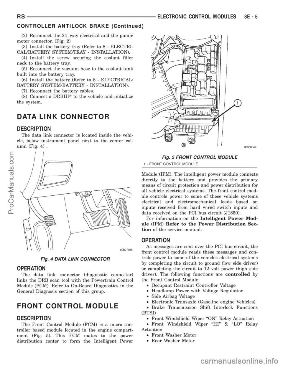
DATA LINK CONNECTOR
DESCRIPTION
The data link connector is located inside the vehi-
cle, below instrument panel next to the center col-
umn (Fig. 4) .
OPERATION
The data link connector (diagnostic connector)
links the DRB scan tool with the Powertrain Control
Module (PCM). Refer to On-Board Diagnostics in the
General Diagnosis section of this group.
FRONT CONTROL MODULE
DESCRIPTION
The Front Control Module (FCM) is a micro con-
troller based module located in the engine compart-
ment (Fig. 5). This FCM mates to the power
distribution center to form the Intelligent PowerModule (IPM). The intelligent power module connects
directly to the battery and provides the primary
means of circuit protection and power distribution for
all vehicle electrical systems. The front control mod-
ule controls power to some of these vehicle systems
electrical and electromechanical loads based on
inputs received from hard wired switch inputs and
data received on the PCI bus circuit (J1850).
For information on theIntelligent Power Mod-
ule(IPM)Refer to the Power Distribution Sec-
tionof the service manual.
OPERATION
As messages are sent over the PCI bus circuit, the
front control module reads these messages and con-
trols power to some of the vehicles electrical systems
by completing the circuit to ground (low side driver)
or completing the circuit to 12 volt power (high side
driver). The following functions arecontrolledby
the Front Control Module:
²Occupant Restraint Controller Voltage
²Headlamp Power with Voltage Regulation
²Side Airbag Voltage
²Electronic Transaxle (Gasoline engine Vehicles)
²Brake Transmission Shift Interlock Functions
(BTSI)
²Front Windshield Wiper ªONº Relay Actuation
²Front Windshield Wiper ªHIº & ªLOº Relay
Actuation
²Front Washer Motor
²Rear Washer Motor
Fig. 4 DATA LINK CONNECTOR
Fig. 5 FRONT CONTROL MODULE
1 - FRONT CONTROL MODULE
RSELECTRONIC CONTROL MODULES8E-5
CONTROLLER ANTILOCK BRAKE (Continued)
ProCarManuals.com
Page 364 of 2321
MEMORY HEATED SEAT/
MIRROR MODULE
REMOVAL
(1) Disconnect and isolate the negative battery
cable.
(2) Move seat to full forward position.
(3) Working under the seat, disconnect the module
wire harness connectors.
(4) Remove the module retaining screws.
(5) Remove the module from under the seat.
INSTALLATION
(1) Install the module under the seat.
(2) Install the module retaining screws.
(3) Working under the seat, connect the module
wire harness connectors.
(4) Connect and isolate the negative battery cable.
POWER LIFTGATE MODULE
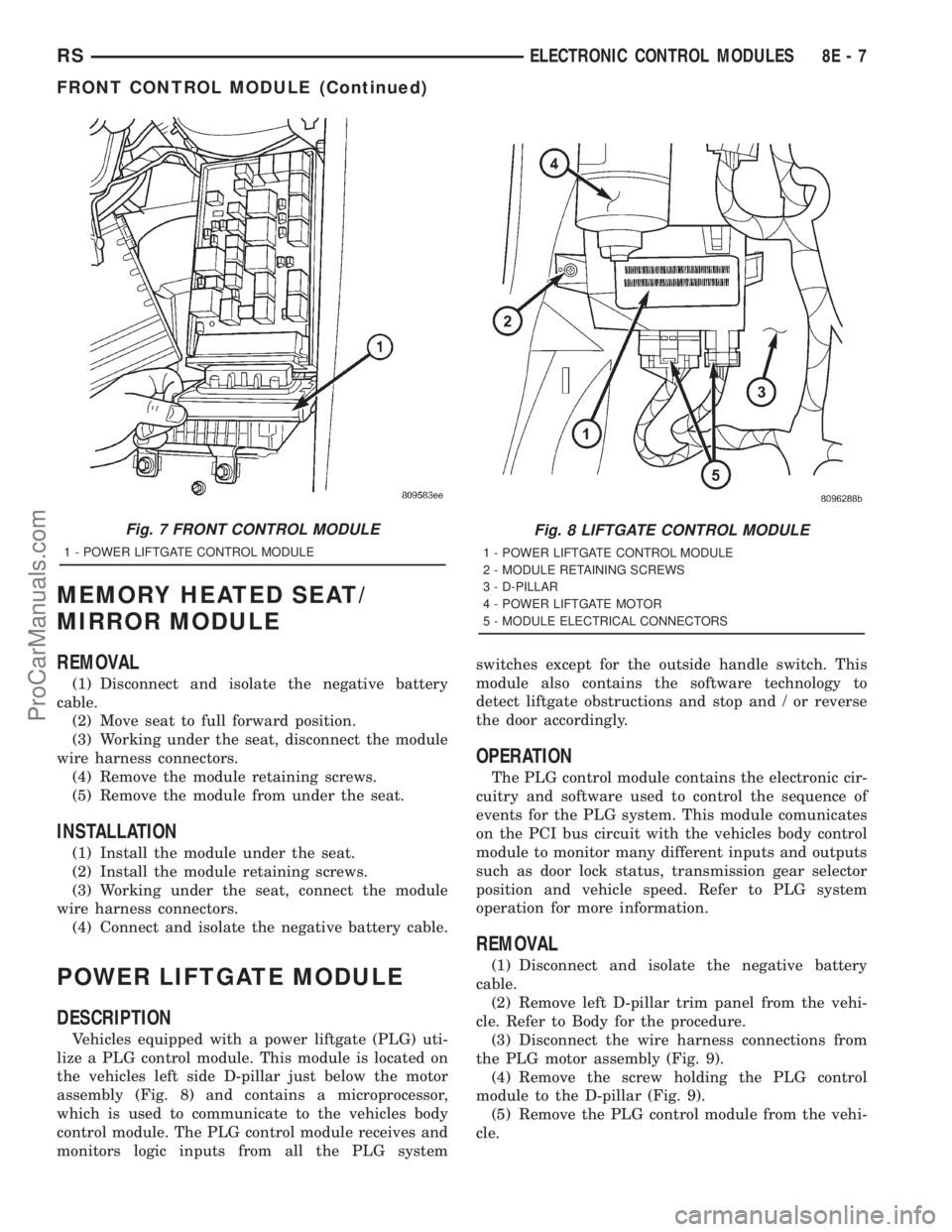
DESCRIPTION
Vehicles equipped with a power liftgate (PLG) uti-
lize a PLG control module. This module is located on
the vehicles left side D-pillar just below the motor
assembly (Fig. 8) and contains a microprocessor,
which is used to communicate to the vehicles body
control module. The PLG control module receives and
monitors logic inputs from all the PLG systemswitches except for the outside handle switch. This
module also contains the software technology to
detect liftgate obstructions and stop and / or reverse
the door accordingly.
OPERATION
The PLG control module contains the electronic cir-
cuitry and software used to control the sequence of
events for the PLG system. This module comunicates
on the PCI bus circuit with the vehicles body control
module to monitor many different inputs and outputs
such as door lock status, transmission gear selector
position and vehicle speed. Refer to PLG system
operation for more information.
REMOVAL
(1) Disconnect and isolate the negative battery
cable.
(2) Remove left D-pillar trim panel from the vehi-
cle. Refer to Body for the procedure.
(3) Disconnect the wire harness connections from
the PLG motor assembly (Fig. 9).
(4) Remove the screw holding the PLG control
module to the D-pillar (Fig. 9).
(5) Remove the PLG control module from the vehi-
cle.
Fig. 7 FRONT CONTROL MODULE
1 - POWER LIFTGATE CONTROL MODULE
Fig. 8 LIFTGATE CONTROL MODULE
1 - POWER LIFTGATE CONTROL MODULE
2 - MODULE RETAINING SCREWS
3 - D-PILLAR
4 - POWER LIFTGATE MOTOR
5 - MODULE ELECTRICAL CONNECTORS
RSELECTRONIC CONTROL MODULES8E-7
FRONT CONTROL MODULE (Continued)
ProCarManuals.com
Page 365 of 2321
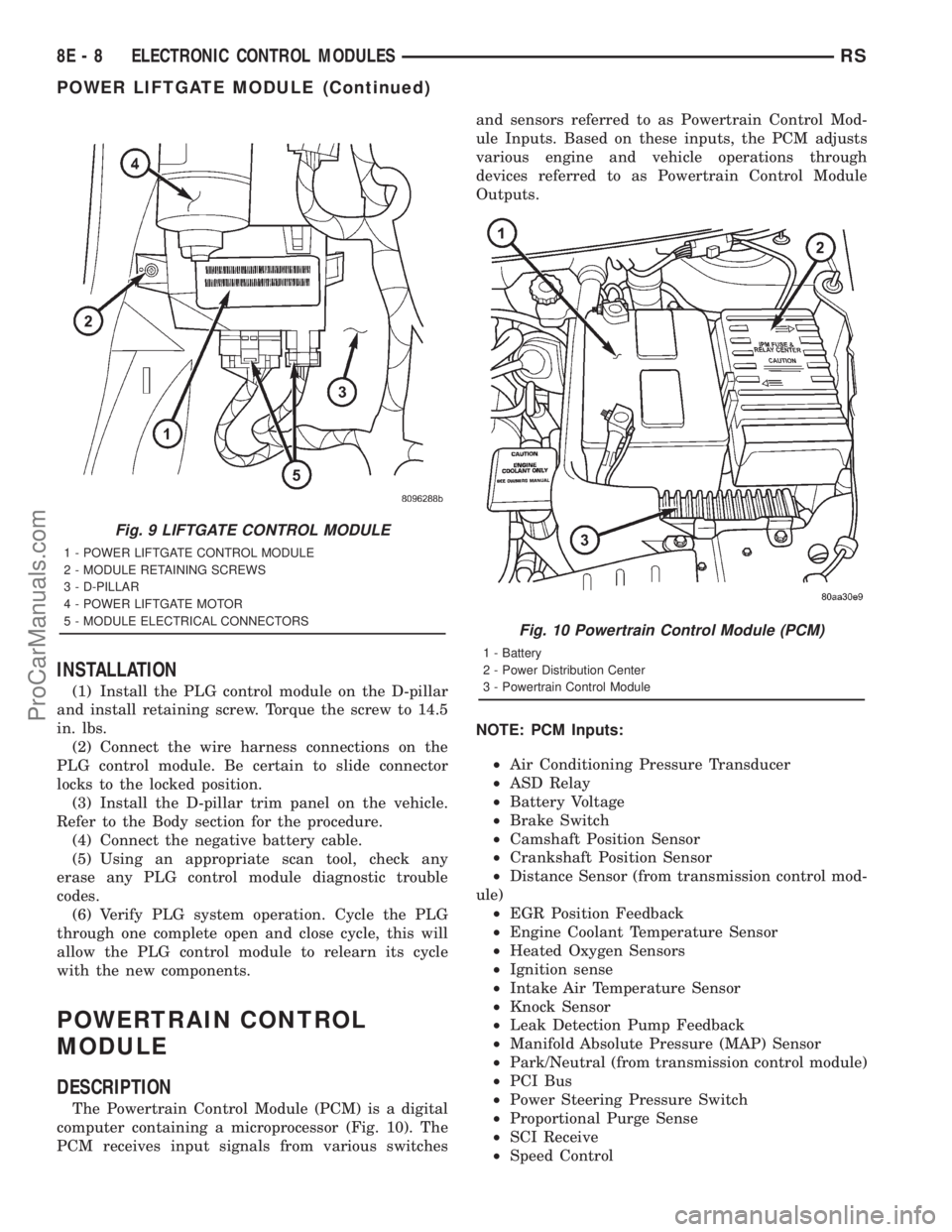
INSTALLATION
(1) Install the PLG control module on the D-pillar
and install retaining screw. Torque the screw to 14.5
in. lbs.
(2) Connect the wire harness connections on the
PLG control module. Be certain to slide connector
locks to the locked position.
(3) Install the D-pillar trim panel on the vehicle.
Refer to the Body section for the procedure.
(4) Connect the negative battery cable.
(5) Using an appropriate scan tool, check any
erase any PLG control module diagnostic trouble
codes.
(6) Verify PLG system operation. Cycle the PLG
through one complete open and close cycle, this will
allow the PLG control module to relearn its cycle
with the new components.
POWERTRAIN CONTROL
MODULE
DESCRIPTION
The Powertrain Control Module (PCM) is a digital
computer containing a microprocessor (Fig. 10). The
PCM receives input signals from various switchesand sensors referred to as Powertrain Control Mod-
ule Inputs. Based on these inputs, the PCM adjusts
various engine and vehicle operations through
devices referred to as Powertrain Control Module
Outputs.
NOTE: PCM Inputs:
²Air Conditioning Pressure Transducer
²ASD Relay
²Battery Voltage
²Brake Switch
²Camshaft Position Sensor
²Crankshaft Position Sensor
²Distance Sensor (from transmission control mod-
ule)
²EGR Position Feedback
²Engine Coolant Temperature Sensor
²Heated Oxygen Sensors
²Ignition sense
²Intake Air Temperature Sensor
²Knock Sensor
²Leak Detection Pump Feedback
²Manifold Absolute Pressure (MAP) Sensor
²Park/Neutral (from transmission control module)
²PCI Bus
²Power Steering Pressure Switch
²Proportional Purge Sense
²SCI Receive
²Speed Control
Fig. 9 LIFTGATE CONTROL MODULE
1 - POWER LIFTGATE CONTROL MODULE
2 - MODULE RETAINING SCREWS
3 - D-PILLAR
4 - POWER LIFTGATE MOTOR
5 - MODULE ELECTRICAL CONNECTORS
Fig. 10 Powertrain Control Module (PCM)
1 - Battery
2 - Power Distribution Center
3 - Powertrain Control Module
8E - 8 ELECTRONIC CONTROL MODULESRS
POWER LIFTGATE MODULE (Continued)
ProCarManuals.com
Page 366 of 2321
²Throttle Position Sensor
²Torque Management Input (From TCM)
²Transaxle Control Module (TCM)
²Transaxle Gear Engagement (From TCM)
²Vehicle Speed (from transmission control mod-
ule)
NOTE: PCM Outputs:
²Air Conditioning Clutch Relay
²Automatic Shut Down (ASD) and Fuel Pump
Relays
²Data Link Connector (PCI and SCI Transmit)
²Double Start Override
²EGR Solenoid
²Fuel Injectors
²Generator Field
²High Speed Fan Relay
²Idle Air Control Motor
²Ignition Coils
²Leak Detection Pump
²Low Speed Fan Relay
²MTV Actuator
²Proportional Purge Solenoid
²SRV Valve
²Speed Control Relay
²Speed Control Vent Relay
²Speed Control Vacuum Relay
²8 Volt Output
²5 Volt Output
Based on inputs it receives, the powertrain control
module (PCM) adjusts fuel injector pulse width, idle
speed, ignition timing, and canister purge operation.
The PCM regulates the cooling fans, air conditioning
and speed control systems. The PCM changes gener-
ator charge rate by adjusting the generator field.
The PCM adjusts injector pulse width (air-fuel
ratio) based on the following inputs.
²Battery Voltage
²Intake Air Temperature Sensor
²Engine Coolant Temperature
²Engine Speed (crankshaft position sensor)
²Exhaust Gas Oxygen Content (heated oxygen
sensors)
²Manifold Absolute Pressure
²Throttle Position
The PCM adjusts engine idle speed through the
idle air control motor based on the following inputs.
²Brake Switch
²Engine Coolant Temperature
²Engine Speed (crankshaft position sensor)
²Park/Neutral (transmission gear selection)
²Transaxle Gear Engagement
²Throttle Position
²Vehicle Speed (from Transmission Control Mod-
ule)The PCM adjusts ignition timing based on the fol-
lowing inputs.
²Intake Air Temperature
²Engine Coolant Temperature
²Engine Speed (crankshaft position sensor)
²Knock Sensor
²Manifold Absolute Pressure
²Park/Neutral (transmission gear selection)
²Transaxle Gear Engagement
²Throttle Position
The automatic shut down (ASD) and fuel pump
relays are mounted externally, but turned on and off
by the powertrain control module through the same
circuit.
The camshaft and crankshaft signals are sent to
the powertrain control module. If the PCM does not
receive both signals within approximately one second
of engine cranking, it deactivates the ASD and fuel
pump relays. When these relays are deactivated,
power is shut off to the fuel injectors, ignition coils,
fuel pump and the heating element in each oxygen
sensor.
The PCM contains a voltage converter that
changes battery voltage to a regulated 8.0 volts. The
8.0 volts power the camshaft position sensor, crank-
shaft position sensor and vehicle speed sensor. The
PCM also provides a 5.0 volts supply for the engine
coolant temperature sensor, intake air temperature
sensor, manifold absolute pressure sensor and throt-
tle position sensor.
The PCM engine control strategy prevents reduced
idle speeds until after the engine operates for 320 km
(200 miles). If the PCM is replaced after 320 km (200
miles) of usage, update the mileage in new PCM. Use
the DRB scan tool to change the mileage in the PCM.
Refer to the appropriate Powertrain Diagnostic Man-
ual and the DRB scan tool.
DIAGNOSTIC TROUBLE CODE
DESCRIPTION
A Diagnostic Trouble Code (DTC) indicates the
PCM has recognized an abnormal condition in the
system.
Remember that DTC's are the results of a sys-
tem or circuit failure, but do not directly iden-
tify the failed component or components.
NOTE: For a list of DTC's, refer to the charts in this
section.
RSELECTRONIC CONTROL MODULES8E-9
POWERTRAIN CONTROL MODULE (Continued)
ProCarManuals.com
Page 371 of 2321
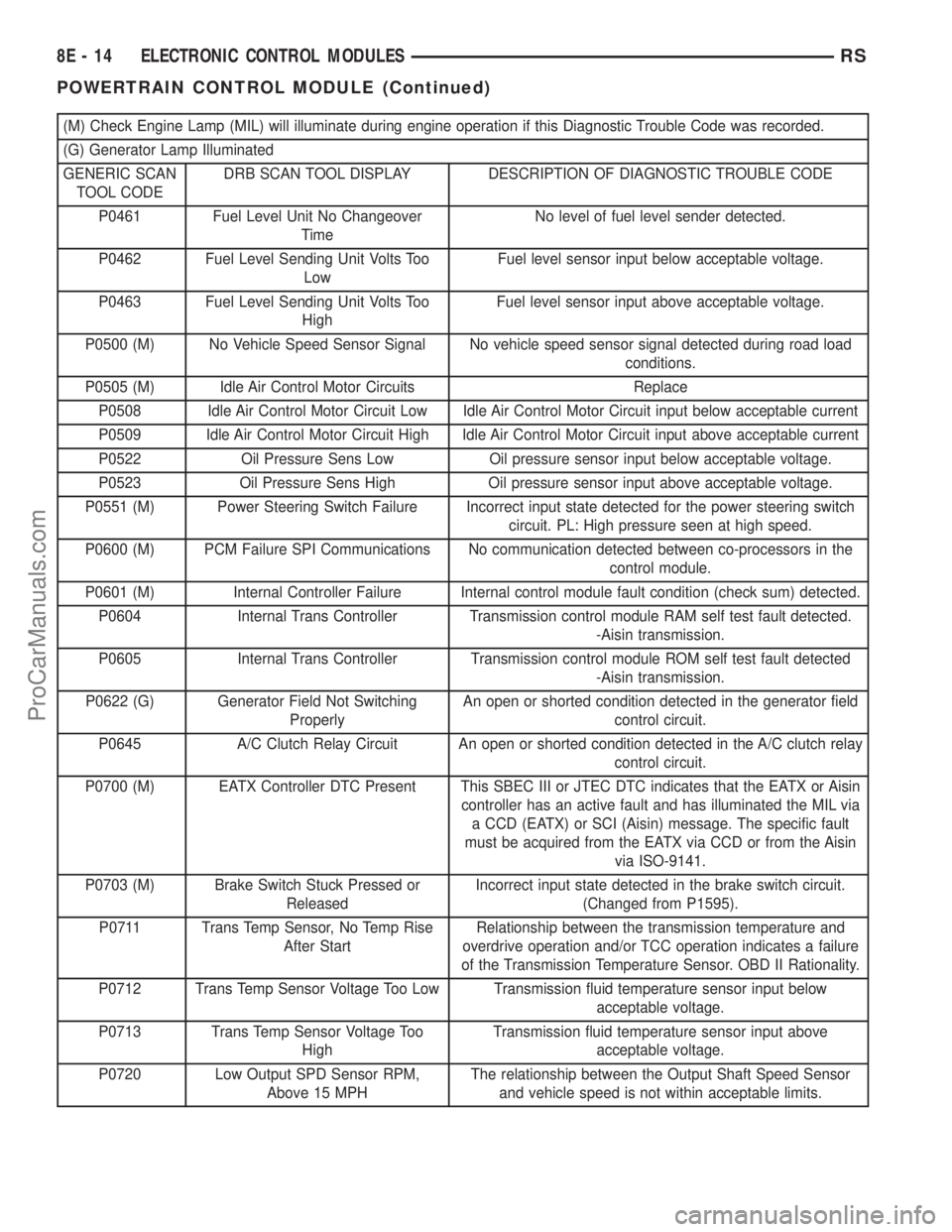
(M) Check Engine Lamp (MIL) will illuminate during engine operation if this Diagnostic Trouble Code was recorded.
(G) Generator Lamp Illuminated
GENERIC SCAN
TOOL CODEDRB SCAN TOOL DISPLAY DESCRIPTION OF DIAGNOSTIC TROUBLE CODE
P0461 Fuel Level Unit No Changeover
TimeNo level of fuel level sender detected.
P0462 Fuel Level Sending Unit Volts Too
LowFuel level sensor input below acceptable voltage.
P0463 Fuel Level Sending Unit Volts Too
HighFuel level sensor input above acceptable voltage.
P0500 (M) No Vehicle Speed Sensor Signal No vehicle speed sensor signal detected during road load
conditions.
P0505 (M) Idle Air Control Motor Circuits Replace
P0508 Idle Air Control Motor Circuit Low Idle Air Control Motor Circuit input below acceptable current
P0509 Idle Air Control Motor Circuit High Idle Air Control Motor Circuit input above acceptable current
P0522 Oil Pressure Sens Low Oil pressure sensor input below acceptable voltage.
P0523 Oil Pressure Sens High Oil pressure sensor input above acceptable voltage.
P0551 (M) Power Steering Switch Failure Incorrect input state detected for the power steering switch
circuit. PL: High pressure seen at high speed.
P0600 (M) PCM Failure SPI Communications No communication detected between co-processors in the
control module.
P0601 (M) Internal Controller Failure Internal control module fault condition (check sum) detected.
P0604 Internal Trans Controller Transmission control module RAM self test fault detected.
-Aisin transmission.
P0605 Internal Trans Controller Transmission control module ROM self test fault detected
-Aisin transmission.
P0622 (G) Generator Field Not Switching
ProperlyAn open or shorted condition detected in the generator field
control circuit.
P0645 A/C Clutch Relay Circuit An open or shorted condition detected in the A/C clutch relay
control circuit.
P0700 (M) EATX Controller DTC Present This SBEC III or JTEC DTC indicates that the EATX or Aisin
controller has an active fault and has illuminated the MIL via
a CCD (EATX) or SCI (Aisin) message. The specific fault
must be acquired from the EATX via CCD or from the Aisin
via ISO-9141.
P0703 (M) Brake Switch Stuck Pressed or
ReleasedIncorrect input state detected in the brake switch circuit.
(Changed from P1595).
P0711 Trans Temp Sensor, No Temp Rise
After StartRelationship between the transmission temperature and
overdrive operation and/or TCC operation indicates a failure
of the Transmission Temperature Sensor. OBD II Rationality.
P0712 Trans Temp Sensor Voltage Too Low Transmission fluid temperature sensor input below
acceptable voltage.
P0713 Trans Temp Sensor Voltage Too
HighTransmission fluid temperature sensor input above
acceptable voltage.
P0720 Low Output SPD Sensor RPM,
Above 15 MPHThe relationship between the Output Shaft Speed Sensor
and vehicle speed is not within acceptable limits.
8E - 14 ELECTRONIC CONTROL MODULESRS
POWERTRAIN CONTROL MODULE (Continued)
ProCarManuals.com
Page 372 of 2321
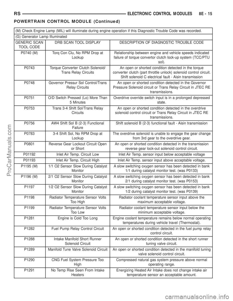
(M) Check Engine Lamp (MIL) will illuminate during engine operation if this Diagnostic Trouble Code was recorded.
(G) Generator Lamp Illuminated
GENERIC SCAN
TOOL CODEDRB SCAN TOOL DISPLAY DESCRIPTION OF DIAGNOSTIC TROUBLE CODE
P0740 (M) Torq Con Clu, No RPM Drop at
LockupRelationship between engine and vehicle speeds indicated
failure of torque convertor clutch lock-up system (TCC/PTU
sol).
P0743 Torque Converter Clutch Solenoid/
Trans Relay CircuitsAn open or shorted condition detected in the torque
converter clutch (part throttle unlock) solenoid control circuit.
Shift solenoid C electrical fault - Aisin transmission
P0748 Governor Pressur Sol Control/Trans
Relay CircuitsAn open or shorted condition detected in the Governor
Pressure Solenoid circuit or Trans Relay Circuit in JTEC RE
transmissions.
P0751 O/D Switch Pressed (Lo) More Than
5 MinutesOverdrive override switch input is in a prolonged depressed
state.
P0753 Trans 3-4 Shift Sol/Trans Relay
CircuitsAn open or shorted condition detected in the overdrive
solenoid control circuit or Trans Relay Circuit in JTEC RE
transmissions.
P0756 AW4 Shift Sol B (2-3) Functional
FailureShift solenoid B (2-3) functional fault - Aisin transmission
P0783 3-4 Shift Sol, No RPM Drop at
LockupThe overdrive solenoid is unable to engage the gear change
from 3rd gear to the overdrive gear.
P0801 Reverse Gear Lockout Circuit Open
or ShortAn open or shorted condition detected in the transmission
reverse gear lock-out solenoid control circuit.
P01192 Inlet Air Temp. Circuit Low Inlet Air Temp. sensor input below acceptable voltage
P01193 Inlet Air Temp. Circuit High Inlet Air Temp. sensor input above acceptable voltage.
P1195 (M) 1/1 O2 Sensor Slow During Catalyst
MonitorA slow switching oxygen sensor has been detected in bank
1/1 during catalyst monitor test. (was P0133)
P1196 (M) 2/1 O2 Sensor Slow During Catalyst
MonitorA slow switching oxygen sensor has been detected in bank
2/1 during catalyst monitor test. (was P0153)
P1197 1/2 O2 Sensor Slow During Catalyst
MonitorA slow switching oxygen sensor has been detected in bank
1/2 during catalyst monitor test. (was P0139)
P1198 Radiator Temperature Sensor Volts
Too HighRadiator coolant temperature sensor input above the
maximum acceptable voltage.
P1199 Radiator Temperature Sensor Volts
Too LowRadiator coolant temperature sensor input below the
minimum acceptable voltage.
P1281 Engine is Cold Too Long Engine coolant temperature remains below normal operating
temperatures during vehicle travel (Thermostat).
P1282 Fuel Pump Relay Control Circuit An open or shorted condition detected in the fuel pump relay
control circuit.
P1288 Intake Manifold Short Runner
Solenoid CircuitAn open or shorted condition detected in the short runner
tuning valve circuit.
P1289 Manifold Tune Valve Solenoid Circuit An open or shorted condition detected in the manifold tuning
valve solenoid control circuit.
P1290 CNG Fuel System Pressure Too
HighCompressed natural gas system pressure above normal
operating range.
P1291 No Temp Rise Seen From Intake
HeatersEnergizing Heated Air Intake does not change intake air
temperature sensor an acceptable amount.
RSELECTRONIC CONTROL MODULES8E-15
POWERTRAIN CONTROL MODULE (Continued)
ProCarManuals.com