oil temperature DODGE TOWN AND COUNTRY 2001 Repair Manual
[x] Cancel search | Manufacturer: DODGE, Model Year: 2001, Model line: TOWN AND COUNTRY, Model: DODGE TOWN AND COUNTRY 2001Pages: 2321, PDF Size: 68.09 MB
Page 1236 of 2321

the cylinder in question.The recommended com-
pression pressures are to be used only as a
guide to diagnosing engine problems. An engine
should not be disassembled to determine the
cause of low compression unless some malfunc-
tion is present.
DIAGNOSIS AND TESTING - CYLINDER
COMBUSTION PRESSURE LEAKAGE
The combustion pressure leakage test provides an
accurate means for determining engine condition.
Combustion pressure leakage testing will detect:
²Exhaust and intake valve leaks (improper seat-
ing).
²Leaks between adjacent cylinders or into water
jacket.
²Any causes for combustion/compression pressure
loss.
WARNING: DO NOT REMOVE THE RADIATOR CAP
WITH THE SYSTEM HOT AND UNDER PRESSURE
BECAUSE SERIOUS BURNS FROM COOLANT CAN
OCCUR.
Check the coolant level and fill as required. DO
NOT install the radiator cap.
Start and operate the engine until it attains nor-
mal operating temperature, then turn the engine
OFF.
Clean spark plug recesses with compressed air.
Remove the spark plugs.
Remove the oil filler cap.
Remove the air cleaner.
Calibrate the tester according to the manufactur-
er's instructions. The shop air source for testing
should maintain 483 kPa (70 psi) minimum, 1,379
kPa (200 psi) maximum, with 552 kPa (80 psi) rec-
ommended.
Perform the test procedures on each cylinder
according to the tester manufacturer's instructions.
While testing, listen for pressurized air escaping
through the throttle body, tailpipe and oil filler cap
opening. Check for bubbles in the radiator coolant.
All gauge pressure indications should be equal,
with no more than 25% leakage per cylinder.
FOR EXAMPLE:At 552 kPa (80 psi) input pres-
sure, a minimum of 414 kPa (60 psi) should be main-
tained in the cylinder.
STANDARD PROCEDURE - MEASURING
BEARING CLEARANCE USING PLASTIGAGE
Engine crankshaft bearing clearances can be deter-
mined by use of Plastigage or equivalent. The follow-
ing is the recommended procedure for the use of
Plastigage:(1) Remove oil film from surface to be checked.
Plastigage is soluble in oil.
(2) Place a piece of Plastigage across the entire
width of the bearing shell in the cap approximately
6.35 mm (1/4 in.) off center and away from the oil
holes (Fig. 3). (In addition, suspected areas can be
checked by placing the Plastigage in the suspected
area). Torque the bearing cap bolts of the bearing
being checked to the proper specifications.
(3) Remove the bearing cap and compare the
width of the flattened Plastigage with the metric
scale provided on the package. Locate the band clos-
est to the same width. This band shows the amount
of clearance in thousandths of a millimeter. Differ-
ences in readings between the ends indicate the
amount of taper present. Record all readings taken.
Compare clearance measurements to specs found in
engine specifications (Refer to 9 - ENGINE - SPECI-
FICATIONS).Plastigage generally is accompa-
nied by two scales. One scale is in inches, the
other is a metric scale.
NOTE: Plastigage is available in a variety of clear-
ance ranges. Use the most appropriate range for
the specifications you are checking.
(4) Install the proper crankshaft bearings to
achieve the specified bearing clearances. (Refer to 9 -
ENGINE/ENGINE BLOCK/CRANKSHAFT MAIN
BEARINGS - STANDARD PROCEDURE) (Refer to 9
- ENGINE/ENGINE BLOCK/CONNECTING ROD
BEARINGS - STANDARD PROCEDURE)
STANDARD PROCEDURE - FORM-IN-PLACE
GASKETS AND SEALERS
There are numerous places where form-in-place
gaskets are used on the engine. Care must be taken
Fig. 3 Plastigage Placed in Lower ShellÐTypical
1 - PLASTIC GAUGE
RSENGINE 3.3/3.8L9-79
ENGINE 3.3/3.8L (Continued)
ProCarManuals.com
Page 1239 of 2321
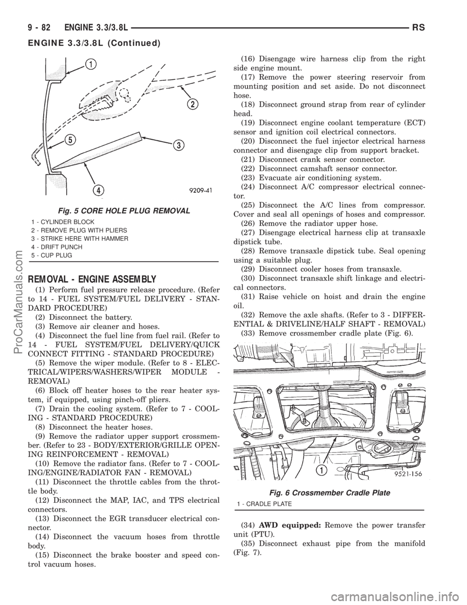
REMOVAL - ENGINE ASSEMBLY
(1) Perform fuel pressure release procedure. (Refer
to 14 - FUEL SYSTEM/FUEL DELIVERY - STAN-
DARD PROCEDURE)
(2) Disconnect the battery.
(3) Remove air cleaner and hoses.
(4) Disconnect the fuel line from fuel rail. (Refer to
14 - FUEL SYSTEM/FUEL DELIVERY/QUICK
CONNECT FITTING - STANDARD PROCEDURE)
(5) Remove the wiper module. (Refer to 8 - ELEC-
TRICAL/WIPERS/WASHERS/WIPER MODULE -
REMOVAL)
(6) Block off heater hoses to the rear heater sys-
tem, if equipped, using pinch-off pliers.
(7) Drain the cooling system. (Refer to 7 - COOL-
ING - STANDARD PROCEDURE)
(8) Disconnect the heater hoses.
(9) Remove the radiator upper support crossmem-
ber. (Refer to 23 - BODY/EXTERIOR/GRILLE OPEN-
ING REINFORCEMENT - REMOVAL)
(10) Remove the radiator fans. (Refer to 7 - COOL-
ING/ENGINE/RADIATOR FAN - REMOVAL)
(11) Disconnect the throttle cables from the throt-
tle body.
(12) Disconnect the MAP, IAC, and TPS electrical
connectors.
(13) Disconnect the EGR transducer electrical con-
nector.
(14) Disconnect the vacuum hoses from throttle
body.
(15) Disconnect the brake booster and speed con-
trol vacuum hoses.(16) Disengage wire harness clip from the right
side engine mount.
(17) Remove the power steering reservoir from
mounting position and set aside. Do not disconnect
hose.
(18) Disconnect ground strap from rear of cylinder
head.
(19) Disconnect engine coolant temperature (ECT)
sensor and ignition coil electrical connectors.
(20) Disconnect the fuel injector electrical harness
connector and disengage clip from support bracket.
(21) Disconnect crank sensor connector.
(22) Disconnect camshaft sensor connector.
(23) Evacuate air conditioning system.
(24) Disconnect A/C compressor electrical connec-
tor.
(25) Disconnect the A/C lines from compressor.
Cover and seal all openings of hoses and compressor.
(26) Remove the radiator upper hose.
(27) Disengage electrical harness clip at transaxle
dipstick tube.
(28) Remove transaxle dipstick tube. Seal opening
using a suitable plug.
(29) Disconnect cooler hoses from transaxle.
(30) Disconnect transaxle shift linkage and electri-
cal connectors.
(31) Raise vehicle on hoist and drain the engine
oil.
(32) Remove the axle shafts. (Refer to 3 - DIFFER-
ENTIAL & DRIVELINE/HALF SHAFT - REMOVAL)
(33) Remove crossmember cradle plate (Fig. 6).
(34)AWD equipped:Remove the power transfer
unit (PTU).
(35) Disconnect exhaust pipe from the manifold
(Fig. 7).
Fig. 5 CORE HOLE PLUG REMOVAL
1 - CYLINDER BLOCK
2 - REMOVE PLUG WITH PLIERS
3 - STRIKE HERE WITH HAMMER
4 - DRIFT PUNCH
5 - CUP PLUG
Fig. 6 Crossmember Cradle Plate
1 - CRADLE PLATE
9 - 82 ENGINE 3.3/3.8LRS
ENGINE 3.3/3.8L (Continued)
ProCarManuals.com
Page 1242 of 2321
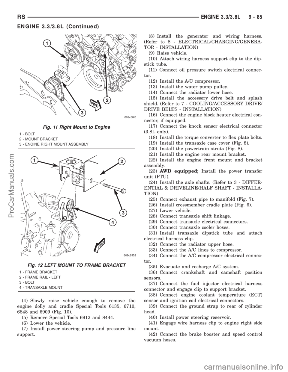
(4) Slowly raise vehicle enough to remove the
engine dolly and cradle Special Tools 6135, 6710,
6848 and 6909 (Fig. 10).
(5) Remove Special Tools 6912 and 8444.
(6) Lower the vehicle.
(7) Install power steering pump and pressure line
support.(8) Install the generator and wiring harness.
(Refer to 8 - ELECTRICAL/CHARGING/GENERA-
TOR - INSTALLATION)
(9) Raise vehicle.
(10) Attach wiring harness support clip to the dip-
stick tube.
(11) Connect oil pressure switch electrical connec-
tor.
(12) Install the A/C compressor.
(13) Install the water pump pulley.
(14) Connect the radiator lower hose.
(15) Install the accessory drive belt and splash
shield. (Refer to 7 - COOLING/ACCESSORY DRIVE/
DRIVE BELTS - INSTALLATION)
(16) Connect the engine block heater electrical con-
nector, if equipped.
(17) Connect the knock sensor electrical connector
(3.8L only).
(18) Install the torque converter to flex plate bolts.
(19) Install the transaxle case cover (Fig. 8).
(20) Install the powertrain struts (Fig. 8).
(21) Install the engine rear mount bracket.
(22) Install the engine front mount and bracket
assembly.
(23)AWD equipped;Install the power transfer
unit (PTU).
(24) Install the axle shafts. (Refer to 3 - DIFFER-
ENTIAL & DRIVELINE/HALF SHAFT - INSTALLA-
TION)
(25) Connect exhaust pipe to manifold (Fig. 7).
(26) Install crossmember cradle plate (Fig. 6).
(27) Lower vehicle.
(28) Connect transaxle shift linkage.
(29) Connect transaxle electrical connectors.
(30) Connect transaxle cooler hoses.
(31) Install transaxle dipstick tube and attach
electrical harness clip.
(32) Connect the radiator upper hose.
(33) Connect the A/C lines to compressor.
(34) Connect the A/C compressor electrical connec-
tor.
(35) Evacuate and recharge A/C system.
(36) Connect crankshaft and camshaft position
sensors.
(37) Connect the fuel injector electrical harness
connector and engage clip to support bracket.
(38) Connect engine coolant temperature (ECT)
sensor and ignition coil electrical connectors.
(39) Connect the ground strap to rear of cylinder
head.
(40) Install power steering reservoir.
(41) Engage wire harness clip to engine right side
mount.
(42) Connect the brake booster and speed control
vacuum hoses.
Fig. 11 Right Mount to Engine
1 - BOLT
2 - MOUNT BRACKET
3 - ENGINE RIGHT MOUNT ASSEMBLY
Fig. 12 LEFT MOUNT TO FRAME BRACKET
1 - FRAME BRACKET
2 - FRAME RAIL - LEFT
3 - BOLT
4 - TRANSAXLE MOUNT
RSENGINE 3.3/3.8L9-85
ENGINE 3.3/3.8L (Continued)
ProCarManuals.com
Page 1276 of 2321
OIL LEVEL TOO HIGH
If oil level is above the MAX mark on dipstick, it is
possible for the connecting rods to dip into the oil
while engine is running and create foaming. Foam in
oil pan would be fed to the hydraulic lifters by the oil
pump causing them to become soft and allow valves
to seat noisily.
OIL LEVEL TOO LOW
Low oil level may allow pump to take in air which
when fed to the lifters it causes them to become soft
and allows valves to seat noisily. Any leaks on intake
side of pump, through which air can be drawn, will
create the same lifter noise. Check the lubrication
system from the intake strainer to the oil pump
cover, including the relief valve retainer cap. When
lifter noise is due to aeration, it may be intermittent
or constant, and usually more than one lifter will be
noisy. When oil level and leaks have been corrected,
the engine should be operated at fast idle to allow all
of the air inside of the lifters to be bled out.
VALVE TRAIN NOISE
To determine source of valve train noise, operate
engine at idle with cylinder head covers removed and
listen for source of the noise.
NOTE: Worn valve guides or cocked springs are
sometimes mistaken for noisy lifters. If such is the
case, noise may be dampened by applying side
thrust on the valve spring. If noise is not apprecia-
bly reduced, it can be assumed the noise is in the
tappet. Inspect the rocker arm push rod sockets
and push rod ends for wear.
Valve lifter noise ranges from light noise to a
heavy click. A light noise is usually caused by exces-
sive leak-down around the unit plunger which will
necessitate replacing the lifter, or by the plunger par-
tially sticking in the lifter body cylinder. A heavy
click is caused either by a lifter check valve not seat-
ing, or by foreign particles becoming wedged between
the plunger and the lifter body causing the plunger
to stick in the down position. This heavy click will be
accompanied by excessive clearance between the
valve stem and rocker arm as valve closes. In either
case, lifter assembly should be removed for inspec-
tion.
REMOVAL
(1) Remove the cylinder head(s). (Refer to 9 -
ENGINE/CYLINDER HEAD - REMOVAL)
(2) Remove the yoke retainer and aligning yokes
(Fig. 71).
(3) Remove the hydraulic lifters. If necessary use
Special Tool C-4129, or equivalent to remove liftersfrom bores. If lifters are to be reused, identify each
lifter to ensure installation in original location.
INSTALLATION
(1) Lubricate the lifters with engine oil.
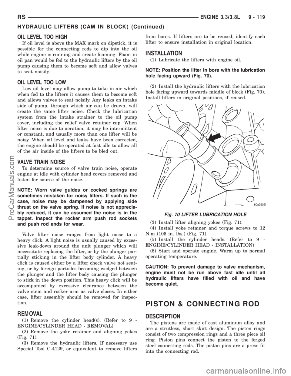
NOTE: Position the lifter in bore with the lubrication
hole facing upward (Fig. 70).
(2) Install the hydraulic lifters with the lubrication
hole facing upward towards middle of block (Fig. 70).
Install lifters in original positions, if reused.
(3) Install lifter aligning yokes (Fig. 71).
(4) Install yoke retainer and torque screws to 12
N´m (105 in. lbs.) (Fig. 71).
(5) Install the cylinder heads. (Refer to 9 -
ENGINE/CYLINDER HEAD - INSTALLATION)
(6) Start and operate engine. Warm up to normal
operating temperature.
CAUTION: To prevent damage to valve mechanism,
engine must not be run above fast idle until all
hydraulic lifters have filled with oil and have
become quiet.
PISTON & CONNECTING ROD
DESCRIPTION
The pistons are made of cast aluminum alloy and
are a strutless, short skirt design. The piston rings
consist of two compression rings and a three piece oil
ring. Piston pins connect the piston to the forged
steel connecting rods. The piston pins are a press fit
into the connecting rod.
Fig. 70 LIFTER LUBRICATION HOLE
RSENGINE 3.3/3.8L9 - 119
HYDRAULIC LIFTERS (CAM IN BLOCK) (Continued)
ProCarManuals.com
Page 1278 of 2321
STANDARD PROCEDURES - FITTING PISTONS
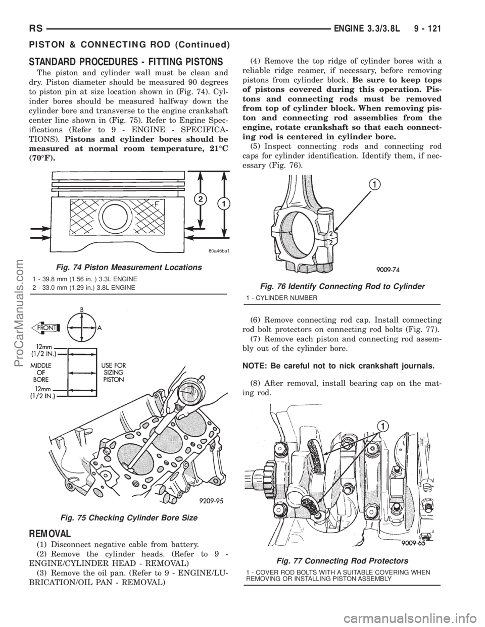
The piston and cylinder wall must be clean and
dry. Piston diameter should be measured 90 degrees
to piston pin at size location shown in (Fig. 74). Cyl-
inder bores should be measured halfway down the
cylinder bore and transverse to the engine crankshaft
center line shown in (Fig. 75). Refer to Engine Spec-
ifications (Refer to 9 - ENGINE - SPECIFICA-
TIONS).Pistons and cylinder bores should be
measured at normal room temperature, 21ÉC
(70ÉF).
REMOVAL
(1) Disconnect negative cable from battery.
(2) Remove the cylinder heads. (Refer to 9 -
ENGINE/CYLINDER HEAD - REMOVAL)
(3) Remove the oil pan. (Refer to 9 - ENGINE/LU-
BRICATION/OIL PAN - REMOVAL)(4) Remove the top ridge of cylinder bores with a
reliable ridge reamer, if necessary, before removing
pistons from cylinder block.Be sure to keep tops
of pistons covered during this operation. Pis-
tons and connecting rods must be removed
from top of cylinder block. When removing pis-
ton and connecting rod assemblies from the
engine, rotate crankshaft so that each connect-
ing rod is centered in cylinder bore.
(5) Inspect connecting rods and connecting rod
caps for cylinder identification. Identify them, if nec-
essary (Fig. 76).
(6) Remove connecting rod cap. Install connecting
rod bolt protectors on connecting rod bolts (Fig. 77).
(7) Remove each piston and connecting rod assem-
bly out of the cylinder bore.
NOTE: Be careful not to nick crankshaft journals.
(8) After removal, install bearing cap on the mat-
ing rod.
Fig. 74 Piston Measurement Locations
1 - 39.8 mm (1.56 in. ) 3.3L ENGINE
2 - 33.0 mm (1.29 in.) 3.8L ENGINE
Fig. 75 Checking Cylinder Bore Size
Fig. 76 Identify Connecting Rod to Cylinder
1 - CYLINDER NUMBER
Fig. 77 Connecting Rod Protectors
1 - COVER ROD BOLTS WITH A SUITABLE COVERING WHEN
REMOVING OR INSTALLING PISTON ASSEMBLY
RSENGINE 3.3/3.8L9 - 121
PISTON & CONNECTING ROD (Continued)
ProCarManuals.com
Page 1305 of 2321

(11) Install throttle and speed control cables.
(Refer to 14 - FUEL SYSTEM/FUEL INJECTION/
THROTTLE CONTROL CABLE - INSTALLATION)
(12) Attach make up air hose clip into the hole in
the throttle cable bracket.
(13) Connect the vapor purge vacuum hose to
throttle body.
(14) Connect the wiring connectors to the throttle
position sensor (TPS) and Automatic Idle Speed (AIS)
motor. (Refer to 9 - ENGINE/MANIFOLDS/INTAKE
MANIFOLD - COMPONENT LOCATION)
(15) Install air cleaner and air inlet hose assembly.
(16) Connect the inlet air sensor electrical connec-
tor. (Refer to 14 - FUEL SYSTEM/FUEL INJEC-
TION/INLET AIR TEMPERATURE SENSOR -
COMPONENT LOCATION)
(17) Connect battery negative cable.
INTAKE MANIFOLD - LOWER
REMOVAL
(1) Perform fuel system pressure release procedure
(before attempting any repairs).(Refer to 14 -
FUEL SYSTEM/FUEL DELIVERY - STANDARD
PROCEDURE)
(2) Drain the cooling system. (Refer to 7 - COOL-
ING - STANDARD PROCEDURE)
(3) Remove the upper intake manifold. (Refer to 9
- ENGINE/MANIFOLDS/INTAKE MANIFOLD -
REMOVAL)
(4) Remove the fuel line. (Refer to 14 - FUEL SYS-
TEM/FUEL DELIVERY/FUEL LINES - STANDARD
PROCEDURE) (Refer to 14 - FUEL SYSTEM/FUEL
DELIVERY/QUICK CONNECT FITTING - STAN-
DARD PROCEDURE)
(5) Remove ignition coil and bracket (Fig. 135).
(6) Disconnect heater supply hose and engine cool-
ant temperature sensor (Fig. 136).
(7) Disconnect the fuel injector wire harness.
(8) Remove the fuel injectors and rail assembly
(Fig. 135).
(9) Remove radiator upper hose.
(10) Remove the intake manifold bolts.
(11) Remove lower intake manifold (Fig. 137).
WARNING: INTAKE MANIFOLD GASKET IS MADE
OF VERY THIN METAL AND MAY CAUSE PER-
SONAL INJURY, HANDLE WITH CARE.
(12) Remove intake manifold seal retainers screws
(Fig. 137). Remove intake manifold gasket.
(13) Inspect and clean manifold. (Refer to 9 -
ENGINE/MANIFOLDS/INTAKE MANIFOLD -
INSPECTION) (Refer to 9 - ENGINE/MANIFOLDS/
INTAKE MANIFOLD - CLEANING)
CLEANING
(1) Discard gasket(s).
(2) Clean all sealing surfaces.
INSPECTION
Check for:
²Damage and cracks of each section.
²Clogged water passages in end cross-overs (if
equipped).
²Check for cylinder head mounting surface distor-
tion using a straightedge and thickness gauge. (Refer
to 9 - ENGINE/CYLINDER HEAD - INSPECTION)
Fig. 135 FUEL RAIL AND IGNITION COIL &
BRACKET
1 - FUEL RAIL
2 - BOLT - FUEL RAIL
3 - NUT - IGNITION COIL
4 - BOLT - IGNITION COIL
5 - IGNITION COIL
6 - BRACKET - IGNITION COIL
7 - STUD - IGNITION COIL
8 - SEPARATOR - SPARK PLUG CABLE
9 - BRACKET - SPARK PLUG CABLE SEPARATOR
10 - BOLT - SEPARATOR BRACKET
11 - BRACKET - SPARK PLUG CABLE SEPARATOR
9 - 148 ENGINE 3.3/3.8LRS
INTAKE MANIFOLD - UPPER 3.8L (Continued)
ProCarManuals.com
Page 1316 of 2321
ENGINE 2.5L TURBO DIESEL
TABLE OF CONTENTS
page page
ENGINE 2.5L TURBO DIESEL
DESCRIPTION............................2
REMOVAL...............................3
INSTALLATION............................6
SPECIFICATIONS.........................7
SPECIAL TOOLS.........................12
CYLINDER HEAD
STANDARD PROCEDURE..................18
VALVE SERVICE.......................18
MEASURING PISTON PROTRUSION........19
REMOVAL..............................20
CLEANING..............................21
INSPECTION............................22
INSTALLATION...........................22
CAMSHAFT(S)
DESCRIPTION...........................23
OPERATION.............................23
REMOVAL..............................23
INSTALLATION...........................24
CYLINDER HEAD COVER(S)
DESCRIPTION...........................24
REMOVAL..............................24
INSTALLATION...........................26
CAMSHAFT OIL SEAL(S)
REMOVAL..............................28
INSTALLATION...........................28
ROCKER ARMS
DESCRIPTION...........................28
OPERATION.............................28
REMOVAL..............................28
INSTALLATION...........................29
HYDRAULIC LIFTERS
DESCRIPTION...........................30
REMOVAL..............................30
INSPECTION............................31
INSTALLATION...........................31
ENGINE BLOCK
DESCRIPTION...........................31
CRANKSHAFT
DESCRIPTION...........................31
OPERATION.............................31
STANDARD PROCEDURE..................32
CHECKING CRANKSHAFT END PLAY.......32
REMOVAL..............................32
INSTALLATION...........................33
CYLINDER LINERS
DESCRIPTION...........................34
REMOVAL..............................34
INSPECTION............................34INSTALLATION...........................35
INTERNAL VACUUM PUMP
DESCRIPTION...........................36
REMOVAL..............................36
INSTALLATION...........................36
PISTON & CONNECTING ROD
DESCRIPTION...........................37
STANDARD PROCEDURE..................37
PISTON RING FITTING..................37
REMOVAL..............................38
INSPECTION............................38
INSTALLATION...........................40
CRANKSHAFT OIL SEAL - FRONT
REMOVAL..............................42
INSTALLATION...........................42
VIBRATION DAMPER
REMOVAL..............................43
INSTALLATION...........................44
ENGINE COVER - FRONT
DESCRIPTION...........................44
REMOVAL..............................44
INSTALLATION...........................45
CRANKSHAFT MAIN BEARINGS
REMOVAL..............................45
INSTALLATION...........................46
CRANKSHAFT OIL SEAL - REAR
REMOVAL..............................46
INSTALLATION...........................46
OIL PAN
REMOVAL..............................46
INSTALLATION...........................47
OIL PUMP
REMOVAL..............................47
INSTALLATION...........................48
OIL PRESSURE SENSOR/SWITCH
DESCRIPTION...........................49
REMOVAL..............................49
INSTALLATION...........................50
OIL TEMPERATURE SENSOR
DESCRIPTION...........................50
REMOVAL..............................50
INSTALLATION...........................50
OIL PRESSURE RELIEF VALVE
DESCRIPTION...........................50
REMOVAL..............................51
INSTALLATION...........................51
OIL COOLER & LINES
REMOVAL..............................51
INSTALLATION...........................52
RGENGINE 2.5L TURBO DIESEL9a-1
ProCarManuals.com
Page 1321 of 2321

(47) Remove left engine mount through bolt.
(48) Raise vehicle, leaving engine and transmis-
sion on engine cradle.
(49) Lift engine from engine cradle and diassemble
as necessary.
REMOVAL - ENGINE COVER
(1) Remove the engine cover retaining bolts.
(2) Remove the engine cover from the engine.
INSTALLATION - 2.5L TURBO DIESEL ENGINE
(1) Reassembly engine and transmission assembly
and install on engine cradle.
(2) Position engine and cradle assembly under
vehicle.
(3) Slowly lower the vehicle down over the engine
and cradle assembly.
(4) Install right engine mount bolts. Torque to
54N´m (40 ft. lbs.)
(5) Install left engine mount through bolt. Torque
to 75N´m (55 ft. lbs.)
(6) Raise vehicle and engine from engine cradle.
Fig. 9 ENGINE COMPONENT LOCATIONS
1 - FUEL INJECTOR RETURN LINE
2 - FUEL INJECTOR SUPPLY LINE
3 - OIL SEPARATOR
4 - FUEL INJECTOR
5 - CAMSHAFT POSITION SENSOR
6 - BOOST PRESSURE/INTAKE AIR TEMPERATURE SENSOR
7 - EGR SOLENOID
8 - FUEL PRESSURE SENSOR
9 - CYLINDER HEAD COVER/INTAKE MANIFOL
10 - FUEL RAIL
11 - WIRING HARNESS RETAINING CLIPS
Fig. 10 REAR ENGINE VIEW
1 - SUSPENSION CRADLE
2 - ENGINE BLOCK
3 - OIL PRESSURE SWITCH
4 - OIL TEMPERATURE SENSOR
5 - VEHICLE SPEED SENSOR
6 - TRANSMISSION
Fig. 11 Figure Caption Here
1 - ENGINE COVER MOUNTING BOLTS
2 - ENGINE COVER
9a - 6 ENGINE 2.5L TURBO DIESELRG
ENGINE 2.5L TURBO DIESEL (Continued)
ProCarManuals.com
Page 1322 of 2321
(7) Attach front engine mount bracket to lower
radiator support. Torque to 54N´m (40 ft. lbs.)
(8) Connect cabin heater coolant hose.
(9) Connect exhaust pipe to the turbocharger
downpipe flange. Torque to 28 N´m (250 in. lbs.)
(10) Connect reverse lamp electrical connector at
transmission.
(11) Connect both shifter cables (Refer to 21 -
TRANSMISSION/TRANSAXLE/MANUAL/GEAR
SHIFT CABLE - INSTALLATION).
(12) Connect the clutch slave cylinder quick dis-
connect connector (RHD only)(Refer to 6 - CLUTCH/
SLAVE CYLINDER - INSTALLATION).
(13) Install engine harness into bracket on trans-
mission.
(14) Lower vehicle.
(15) Connect fuel supply and return lines.
(16) Connect A/C lines to A/C compressor. Torque
to 23N´m (17 ft. lbs.)
(17) Route engine wiring harnes to proper location.
(18) Connect engine harness ground cables to
engine block
(19) Connect starter solenoid electrical connector
and battery feed wire to starter. Torque to 10N´m (90
in. lbs.)
(20) Connect A/C compressor, injection pump, glow
plugs, and coolant temperature sensor electrical con-
nectors.
(21) Connect generator electrical connector. Torque
to 9N´m (75 in. lbs.)
(22) Connect the fuel injector, fuel pressure sensor,
boost pressure/intake air temp sensor, cam sensor,
and egr solenoid electrical connectors (Fig. 9).
(23) Connect egr solenoid vacuum supply line to
brake boost vacuum supply line.
(24) Connect brake booster vacuum supply line.
(25) Connect heater core return hose to coolant
pipe.
(26) Connect lower radiator hose to engine (Fig. 8).
(27) Install charger air cooler inlet hose (Fig. 7).
(28) Install charge air cooler outlet hose (Fig. 7).
(29) Connect upper radiator hose to engine (Fig.
8).
(30) Install battery shield.
(31) Install coolant reserve pressure container
(Refer to 7 - COOLING/ENGINE/COOLANT RECOV-
ERY PRESS CONTAINER - INSTALLATION).
(32) Install power steering reservoir and bracket
(Fig. 5).
(33) Raise vehicle
(34) Connect oil pressure sensor, oil temperature
sensor, engine speed sensor, and vehicle speed sensor
electrical connector (Fig. 10).(35) Install suspension cradle in vehicle (Refer to
13 - FRAME & BUMPERS/FRAME/ENGINE CRA-
DLE CROSSMEMBER - INSTALLATION).
(36) Install both axle shaft assemblies (Refer to 3 -
DIFFERENTIAL & DRIVELINE/HALF SHAFT -
INSTALLATION).
(37) Connect the power steering supply, pressure,
and return lines to power steering pump (Fig. 5).
(38) Install the power steering line brackets on oil
pan (Fig. 5).
(39) Install lower splash shield and side panels.
(40) Install both front wheel and tire assemblies.
(41) Lower vehicle.
(42) Install air cleaner housing, MAF sensor, and
air intake tube assembly (Fig. 4).
(43) Refill transmission to proper level (Refer to 21
- TRANSMISSION/TRANSAXLE/MANUAL/FLUID -
STANDARD PROCEDURE).
(44) Refill engine coolant (Refer to 7 - COOLING/
ENGINE/COOLANT - STANDARD PROCEDURE).
(45) Recharge A/C system (Refer to 24 - HEATING
& AIR CONDITIONING/PLUMBING/REFRIGER-
ANT - STANDARD PROCEDURE) .
(46) Install engine cover (Refer to 9 - ENGINE -
INSTALLATION) (Fig. 3).
(47) Connect negative battery cable.
INSTALLATION - ENGINE COVER
(1) Install engine cover on engine.
(2) Install the engine cover mounting bolts (Fig.
11).
SPECIFICATIONS
SPECIFICATIONS - 2.5L COMMON RAIL
DIESEL ENGINE
ENGINE SPECIFICATIONS
DESCRIPTION SPECIFICATION
Type R2516C
Number of Cylinders 4
Bore 92 mm
Stroke 94 mm
Displacement 2499.5cc
Injection Order 1-3-4-2
Compression Ratio 17.5:1 ( 0.5)
Maximum Power 103kW (140 HP) @ 4000
RPM
Peak Torque 340Nm (34.6 kgm) @
1800 RPM
RGENGINE 2.5L TURBO DIESEL9a-7
ENGINE 2.5L TURBO DIESEL (Continued)
ProCarManuals.com
Page 1337 of 2321

INSPECTION
Use a straightedge and feeler gauge to check the
flatness of the engine cylinder head and block mating
surfaces.
The minimum cylinder head thickness is 89.95mm
(3.541 in.).
INSTALLATION
CAUTION: Piston protrusion must be measured to
determine cylinder head gasket thickness if one or
more cylinder liners have benn replaced (Refer to 9
- ENGINE/CYLINDER HEAD - STANDARD PROCE-
DURE).
NOTE: If cylinder liner(s) have not been removed,
the same thickness head gasket that was removed
can be used.(1) Clean and inspect gasket mating surfaces.
(2) Position correct head gasket on engine block.
(3) Place cylinder head on engine block (Fig. 19).
CAUTION: New cylinder head bolts must be uesd.
(4) Tighten cylinder head bolts following procedure
below.
Cylinder Head Bolt Torquing Procedure
(1) Lubricate cylinder head bolts with engine oil.
(2) Torque bolts to 30N´m in numerical starting
with bolt #1 (Fig. 20).
(3) Tighten all bolts an additional 50É, starting
with bolt #4 then 5-6-7-8-9-10-1-2-3-11-12-13-14-15-
16-17-18 (Fig. 20).
(4) Finally tighten all bolts an additional 75É in
numerical order starting with bolt #1 (Fig. 20).
(5) Slide exhaust manifold and turbocharger on
exhaust manifold studs (Fig. 18).
(6) Install exhaust manifold retaining nuts. Torque
nuts to 32.4N´m.
(7) Install exhaust manifold heat shield (Fig. 18).
Torque bolts to 27.5N´m.
(8) Install turbocharger outlet to charge air cooler
pipe (Fig. 17).
(9) Install thermostat housing to upper radiator
hose pipe (Fig. 17). Install retaining bolt and torque
to 47.1N´m.
(10) Install coolant recovery pressure container
(Refer to 7 - COOLING/ENGINE/COOLANT RECOV-
ERY PRESS CONTAINER - INSTALLATION).
Fig. 19 CYLINDER HEAD ASSEMBLY
1 - VALVE SPRING
2 - CYLINDER HEAD BOLT
3 - GLOW PLUG
4 - COOLANT TEMPERATURE SENSOR
5 - CYLINDER HEAD ALIGNMENT DOWEL
6 - CYLINDER BLOCK
7 - CYLINDER LINER
8 - ENGINE BLOCK DECK
9 - CYLINDER HEAD GASKET
10 - CYLINDER HEAD
11 - ROCKER ARM AND LIFTER ASSEMBLY
Fig. 20 CYLINDER HEAD TORQUE SEQUENCE
9a - 22 ENGINE 2.5L TURBO DIESELRG
CYLINDER HEAD (Continued)
ProCarManuals.com