torque DODGE TOWN AND COUNTRY 2001 Manual PDF
[x] Cancel search | Manufacturer: DODGE, Model Year: 2001, Model line: TOWN AND COUNTRY, Model: DODGE TOWN AND COUNTRY 2001Pages: 2321, PDF Size: 68.09 MB
Page 189 of 2321
(2) Install adapter mounting bolts and tighten to
169 N´m (125 ft. lbs.) torque.
(3) Install brake shoes, disc brake caliper and
wheel and tire assembly. (Refer to 5 - BRAKES/HY-
DRAULIC/MECHANICAL/BRAKE PADS/SHOES -
INSTALLATION)
(4) Lower vehicle.
(5) Pump the brake pedal several times to set the
pads to the brake rotor.
(6) Check and adjust brake fluid level as neces-
sary.
DISC BRAKE CALIPER GUIDE
PINS
REMOVAL - DISC BRAKE CALIPER GUIDE PINS
(DISC/DRUM BRAKES)
(1) Raise the vehicle. Refer to HOISTING in
LUBRICATION AND MAINTENANCE.
(2) Remove the front tire and wheel assembly.
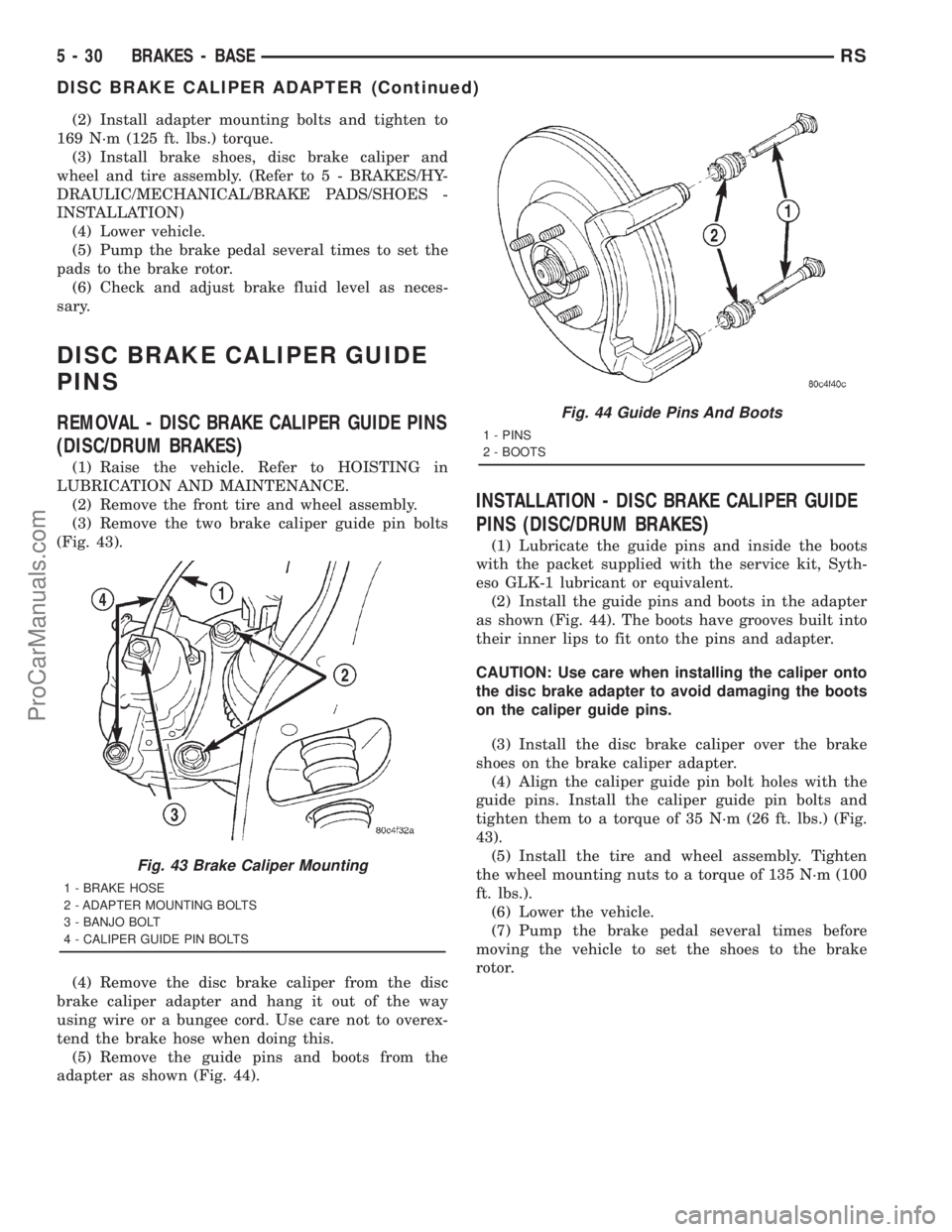
(3) Remove the two brake caliper guide pin bolts
(Fig. 43).
(4) Remove the disc brake caliper from the disc
brake caliper adapter and hang it out of the way
using wire or a bungee cord. Use care not to overex-
tend the brake hose when doing this.
(5) Remove the guide pins and boots from the
adapter as shown (Fig. 44).
INSTALLATION - DISC BRAKE CALIPER GUIDE
PINS (DISC/DRUM BRAKES)
(1) Lubricate the guide pins and inside the boots
with the packet supplied with the service kit, Syth-
eso GLK-1 lubricant or equivalent.
(2) Install the guide pins and boots in the adapter
as shown (Fig. 44). The boots have grooves built into
their inner lips to fit onto the pins and adapter.
CAUTION: Use care when installing the caliper onto
the disc brake adapter to avoid damaging the boots
on the caliper guide pins.
(3) Install the disc brake caliper over the brake
shoes on the brake caliper adapter.
(4) Align the caliper guide pin bolt holes with the
guide pins. Install the caliper guide pin bolts and
tighten them to a torque of 35 N´m (26 ft. lbs.) (Fig.
43).
(5) Install the tire and wheel assembly. Tighten
the wheel mounting nuts to a torque of 135 N´m (100
ft. lbs.).
(6) Lower the vehicle.
(7) Pump the brake pedal several times before
moving the vehicle to set the shoes to the brake
rotor.
Fig. 43 Brake Caliper Mounting
1 - BRAKE HOSE
2 - ADAPTER MOUNTING BOLTS
3 - BANJO BOLT
4 - CALIPER GUIDE PIN BOLTS
Fig. 44 Guide Pins And Boots
1 - PINS
2 - BOOTS
5 - 30 BRAKES - BASERS
DISC BRAKE CALIPER ADAPTER (Continued)
ProCarManuals.com
Page 190 of 2321
DRUM
STANDARD PROCEDURE - BRAKE DRUM
MACHINING
Measure the runout and diameter of the rear brake
using only accurate measuring equipment. There
should be no variation in the drum diameter greater
than 0.090 mm (0.004 inch). Drum runout should not
exceed 0.15 mm (0.006 inch) out of round. If the
drum runout or diameter variation exceed these val-
ues the drum should be refaced. For best results in
eliminating the irregularities that cause brake rough-
ness and surge, the amount of material removed dur-
ing a single cut should be limited to 0.13 mm (0.005
inch). When the entire braking surface has been
cleaned, a final cut of 0.0254 mm (0.001 inch) will
assure a good drum surface providing the equipment
used is capable of the precision required for resurfac-
ing brake drums. Deeper cuts are permissible for the
sole purpose of removing deep score marks.Do not
reface more than 1.52 mm (0.060 inch) over the
standard drum diameter.
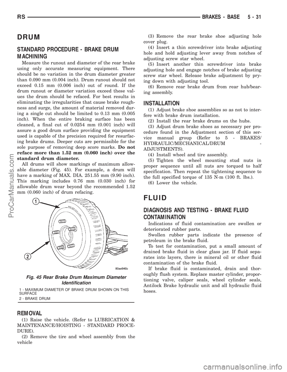
All drums will show markings of maximum allow-
able diameter (Fig. 45). For example, a drum will
have a marking of MAX. DIA. 251.55 mm (9.90 inch).
This marking includes 0.76 mm (0.030 inch) for
allowable drum wear beyond the recommended 1.52
mm (0.060 inch) of drum refacing.
REMOVAL
(1) Raise the vehicle. (Refer to LUBRICATION &
MAINTENANCE/HOISTING - STANDARD PROCE-
DURE).
(2) Remove the tire and wheel assembly from the
vehicle(3) Remove the rear brake shoe adjusting hole
cover plug.
(4) Insert a thin screwdriver into brake adjusting
hole and hold adjusting lever away from notches of
adjusting screw star wheel.
(5) Insert another thin screwdriver into brake
adjusting hole and engage notches of brake adjusting
screw star wheel. Release brake adjustment by pry-
ing down with adjusting tool.
(6) Remove rear brake drum from rear hub/bear-
ing assembly.
INSTALLATION
(1) Adjust brake shoe assemblies so as not to inter-
fere with brake drum installation.
(2) Install the rear brake drums on the hubs.
(3) Adjust drum brake shoes as necessary per pro-
cedure found in the Adjustment section of this ser-
vice manual group (Refer to 5 - BRAKES/
HYDRAULIC/MECHANICAL/DRUM -
ADJUSTMENTS).
(4) Install wheel and tire assembly.
(5) Tighten the wheel mounting stud nuts in
proper sequence until all nuts are torqued to half
specification. Then repeat the tightening sequence to
the full specified torque of 135 N´m (100 ft. lbs.).
(6) Lower the vehicle.
FLUID
DIAGNOSIS AND TESTING - BRAKE FLUID
CONTAMINATION
Indications of fluid contamination are swollen or
deteriorated rubber parts.
Swollen rubber parts indicate the presence of
petroleum in the brake fluid.
To test for contamination, put a small amount of
drained brake fluid in clear glass jar. If fluid sepa-
rates into layers, there is mineral oil or other fluid
contamination of the brake fluid.
If brake fluid is contaminated, drain and thor-
oughly flush system. Replace master cylinder, propor-
tioning valve, caliper seals, wheel cylinder seals,
Antilock Brake hydraulic unit and all hydraulic fluid
hoses.
Fig. 45 Rear Brake Drum Maximum Diameter
Identification
1 - MAXIMUM DIAMETER OF BRAKE DRUM SHOWN ON THIS
SURFACE
2 - BRAKE DRUM
RSBRAKES - BASE5-31
ProCarManuals.com
Page 192 of 2321
(4) Remove the four chassis brake tubes from the
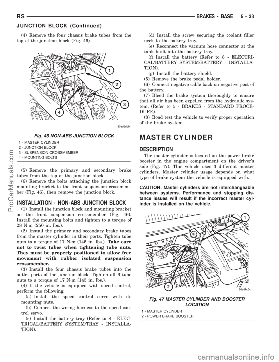
top of the junction block (Fig. 46).
(5) Remove the primary and secondary brake
tubes from the top of the junction block.
(6) Remove the bolts attaching the junction block
mounting bracket to the front suspension crossmem-
ber (Fig. 46), then remove the junction block.
INSTALLATION - NON-ABS JUNCTION BLOCK
(1) Install the junction block and mounting bracket
on the front suspension crossmember (Fig. 46).
Install the mounting bolts and tighten to a torque of
28 N´m (250 in. lbs.).
(2) Install the primary and secondary brake tubes
from the master cylinder in their ports. Tighten tube
nuts to a torque of 17 N´m (145 in. lbs.).Take care
not to twist tubes when tightening tube nuts.
They must be properly positioned to allow free
movement with rubber isolated suspension
crossmember.
(3) Install the four chassis brake tubes into the
outlet ports of the junction block. Tighten all 6 tube
nuts to a torque of 17 N´m (145 in. lbs.).
(4) If the vehicle is equipped with speed control,
perform the following:
(a) Install the speed control servo with its
mounting nuts.
(b) Connect the wiring harness to the speed con-
trol servo.
(c) Install the battery tray (Refer to 8 - ELEC-
TRICAL/BATTERY SYSTEM/TRAY - INSTALLA-
TION).(d) Install the screw securing the coolant filler
neck to the battery tray.
(e) Reconnect the vacuum hose connector at the
tank built into the battery tray.
(f) Install the battery (Refer to 8 - ELECTRI-
CAL/BATTERY SYSTEM/BATTERY - INSTALLA-
TION).
(g) Install the battery shield.
(5) Remove the brake pedal holder.
(6) Connect negative cable back on negative post of
the battery.
(7) Bleed the brake system thoroughly to ensure
that all air has been expelled from the hydraulic sys-
tem. (Refer to 5 - BRAKES - STANDARD PROCE-
DURE).
(8) Road test the vehicle to verify proper operation
of the brake system.
MASTER CYLINDER
DESCRIPTION
The master cylinder is located on the power brake
booster in the engine compartment on the driver's
side (Fig. 47). This vehicle uses 3 different master
cylinders. Master cylinder usage depends on what
type of brake system the vehicle is equipped with.
CAUTION: Master cylinders are not interchangeable
between systems. Performance and stopping dis-
tance issues will result if the incorrect master cyl-
inder is installed on the vehicle.
Fig. 46 NON-ABS JUNCTION BLOCK
1 - MASTER CYLINDER
2 - JUNCTION BLOCK
3 - SUSPENSION CROSSMEMBER
4 - MOUNTING BOLTS
Fig. 47 MASTER CYLINDER AND BOOSTER
LOCATION
1 - MASTER CYLINDER
2 - POWER BRAKE BOOSTER
RSBRAKES - BASE5-33
JUNCTION BLOCK (Continued)
ProCarManuals.com
Page 195 of 2321
ASSEMBLY - MASTER CYLINDER (FLUID
RESERVOIR)
(1) Install new master cylinder housing to brake
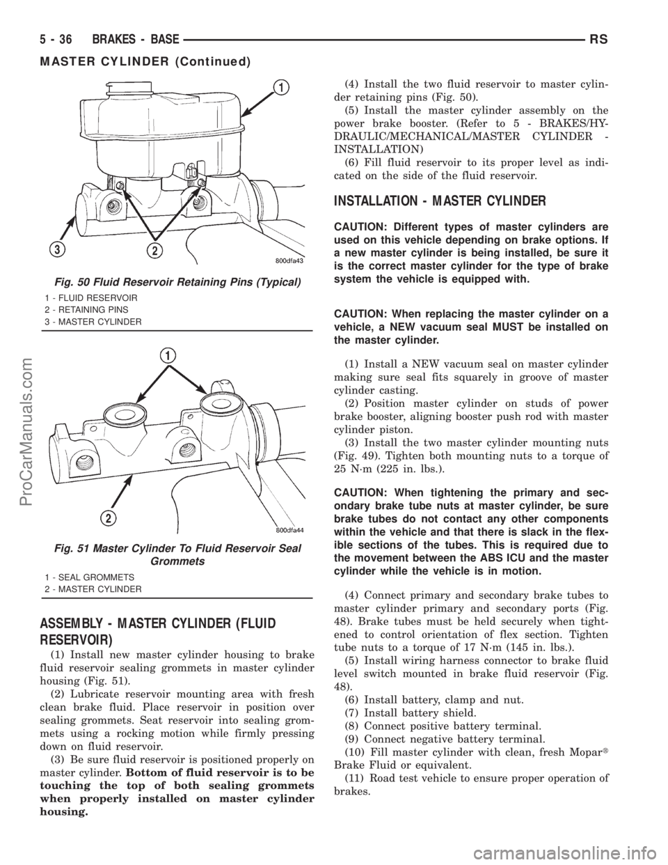
fluid reservoir sealing grommets in master cylinder
housing (Fig. 51).
(2) Lubricate reservoir mounting area with fresh
clean brake fluid. Place reservoir in position over
sealing grommets. Seat reservoir into sealing grom-
mets using a rocking motion while firmly pressing
down on fluid reservoir.
(3) Be sure fluid reservoir is positioned properly on
master cylinder.Bottom of fluid reservoir is to be
touching the top of both sealing grommets
when properly installed on master cylinder
housing.(4) Install the two fluid reservoir to master cylin-
der retaining pins (Fig. 50).
(5) Install the master cylinder assembly on the
power brake booster. (Refer to 5 - BRAKES/HY-
DRAULIC/MECHANICAL/MASTER CYLINDER -
INSTALLATION)
(6) Fill fluid reservoir to its proper level as indi-
cated on the side of the fluid reservoir.
INSTALLATION - MASTER CYLINDER
CAUTION: Different types of master cylinders are
used on this vehicle depending on brake options. If
a new master cylinder is being installed, be sure it
is the correct master cylinder for the type of brake
system the vehicle is equipped with.
CAUTION: When replacing the master cylinder on a
vehicle, a NEW vacuum seal MUST be installed on
the master cylinder.
(1) Install a NEW vacuum seal on master cylinder
making sure seal fits squarely in groove of master
cylinder casting.
(2) Position master cylinder on studs of power
brake booster, aligning booster push rod with master
cylinder piston.
(3) Install the two master cylinder mounting nuts
(Fig. 49). Tighten both mounting nuts to a torque of
25 N´m (225 in. lbs.).
CAUTION: When tightening the primary and sec-
ondary brake tube nuts at master cylinder, be sure
brake tubes do not contact any other components
within the vehicle and that there is slack in the flex-
ible sections of the tubes. This is required due to
the movement between the ABS ICU and the master
cylinder while the vehicle is in motion.
(4) Connect primary and secondary brake tubes to
master cylinder primary and secondary ports (Fig.
48). Brake tubes must be held securely when tight-
ened to control orientation of flex section. Tighten
tube nuts to a torque of 17 N´m (145 in. lbs.).
(5) Install wiring harness connector to brake fluid
level switch mounted in brake fluid reservoir (Fig.
48).
(6) Install battery, clamp and nut.
(7) Install battery shield.
(8) Connect positive battery terminal.
(9) Connect negative battery terminal.
(10) Fill master cylinder with clean, fresh Mopart
Brake Fluid or equivalent.
(11) Road test vehicle to ensure proper operation of
brakes.
Fig. 50 Fluid Reservoir Retaining Pins (Typical)
1 - FLUID RESERVOIR
2 - RETAINING PINS
3 - MASTER CYLINDER
Fig. 51 Master Cylinder To Fluid Reservoir Seal
Grommets
1 - SEAL GROMMETS
2 - MASTER CYLINDER
5 - 36 BRAKES - BASERS
MASTER CYLINDER (Continued)
ProCarManuals.com
Page 199 of 2321
(19) Rotate screwdriver enough to allow retaining
clip center tang to pass over end of brake pedal pin.
Then pull retaining clip off brake pedal pin.Discard
retaining clip. It is not to be reused. Replace
only with a new retaining clip when assem-
bling.
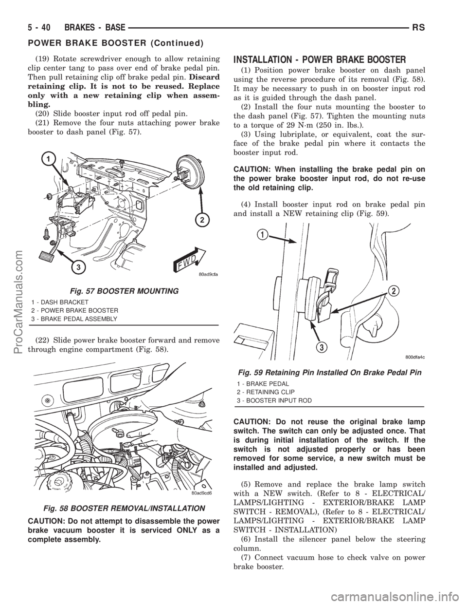
(20) Slide booster input rod off pedal pin.
(21) Remove the four nuts attaching power brake
booster to dash panel (Fig. 57).
(22) Slide power brake booster forward and remove
through engine compartment (Fig. 58).
CAUTION: Do not attempt to disassemble the power
brake vacuum booster it is serviced ONLY as a
complete assembly.INSTALLATION - POWER BRAKE BOOSTER
(1) Position power brake booster on dash panel
using the reverse procedure of its removal (Fig. 58).
It may be necessary to push in on booster input rod
as it is guided through the dash panel.
(2) Install the four nuts mounting the booster to
the dash panel (Fig. 57). Tighten the mounting nuts
to a torque of 29 N´m (250 in. lbs.).
(3) Using lubriplate, or equivalent, coat the sur-
face of the brake pedal pin where it contacts the
booster input rod.
CAUTION: When installing the brake pedal pin on
the power brake booster input rod, do not re-use
the old retaining clip.
(4) Install booster input rod on brake pedal pin
and install a NEW retaining clip (Fig. 59).
CAUTION: Do not reuse the original brake lamp
switch. The switch can only be adjusted once. That
is during initial installation of the switch. If the
switch is not adjusted properly or has been
removed for some service, a new switch must be
installed and adjusted.
(5) Remove and replace the brake lamp switch
with a NEW switch. (Refer to 8 - ELECTRICAL/
LAMPS/LIGHTING - EXTERIOR/BRAKE LAMP
SWITCH - REMOVAL), (Refer to 8 - ELECTRICAL/
LAMPS/LIGHTING - EXTERIOR/BRAKE LAMP
SWITCH - INSTALLATION)
(6) Install the silencer panel below the steering
column.
(7) Connect vacuum hose to check valve on power
brake booster.
Fig. 57 BOOSTER MOUNTING
1 - DASH BRACKET
2 - POWER BRAKE BOOSTER
3 - BRAKE PEDAL ASSEMBLY
Fig. 58 BOOSTER REMOVAL/INSTALLATION
Fig. 59 Retaining Pin Installed On Brake Pedal Pin
1 - BRAKE PEDAL
2 - RETAINING CLIP
3 - BOOSTER INPUT ROD
5 - 40 BRAKES - BASERS
POWER BRAKE BOOSTER (Continued)
ProCarManuals.com
Page 200 of 2321
CAUTION: The master cylinder (and its rear seal) is
used to create the seal for holding vacuum in the
vacuum booster. The vacuum seal on the master
cylinder MUST be replaced with a NEW seal when-
ever the master cylinder is removed from the vac-
uum booster.
CAUTION: When removing the vacuum seal from
the master cylinder do not use a sharp tool.
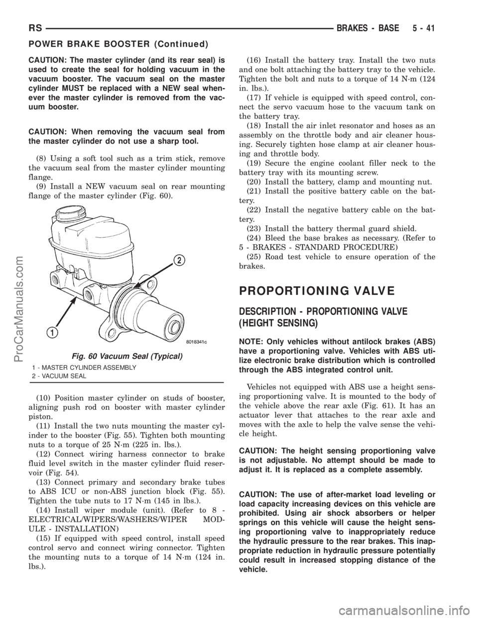
(8) Using a soft tool such as a trim stick, remove
the vacuum seal from the master cylinder mounting
flange.
(9) Install a NEW vacuum seal on rear mounting
flange of the master cylinder (Fig. 60).
(10) Position master cylinder on studs of booster,
aligning push rod on booster with master cylinder
piston.
(11) Install the two nuts mounting the master cyl-
inder to the booster (Fig. 55). Tighten both mounting
nuts to a torque of 25 N´m (225 in. lbs.).
(12) Connect wiring harness connector to brake
fluid level switch in the master cylinder fluid reser-
voir (Fig. 54).
(13) Connect primary and secondary brake tubes
to ABS ICU or non-ABS junction block (Fig. 55).
Tighten the tube nuts to 17 N´m (145 in lbs.).
(14) Install wiper module (unit). (Refer to 8 -
ELECTRICAL/WIPERS/WASHERS/WIPER MOD-
ULE - INSTALLATION)
(15) If equipped with speed control, install speed
control servo and connect wiring connector. Tighten
the mounting nuts to a torque of 14 N´m (124 in.
lbs.).(16) Install the battery tray. Install the two nuts
and one bolt attaching the battery tray to the vehicle.
Tighten the bolt and nuts to a torque of 14 N´m (124
in. lbs.).
(17) If vehicle is equipped with speed control, con-
nect the servo vacuum hose to the vacuum tank on
the battery tray.
(18) Install the air inlet resonator and hoses as an
assembly on the throttle body and air cleaner hous-
ing. Securely tighten hose clamp at air cleaner hous-
ing and throttle body.
(19) Secure the engine coolant filler neck to the
battery tray with its mounting screw.
(20) Install the battery, clamp and mounting nut.
(21) Install the positive battery cable on the bat-
tery.
(22) Install the negative battery cable on the bat-
tery.
(23) Install the battery thermal guard shield.
(24) Bleed the base brakes as necessary. (Refer to
5 - BRAKES - STANDARD PROCEDURE)
(25) Road test vehicle to ensure operation of the
brakes.
PROPORTIONING VALVE
DESCRIPTION - PROPORTIONING VALVE
(HEIGHT SENSING)
NOTE: Only vehicles without antilock brakes (ABS)
have a proportioning valve. Vehicles with ABS uti-
lize electronic brake distribution which is controlled
through the ABS integrated control unit.
Vehicles not equipped with ABS use a height sens-
ing proportioning valve. It is mounted to the body of
the vehicle above the rear axle (Fig. 61). It has an
actuator lever that attaches to the rear axle and
moves with the axle to help the valve sense the vehi-
cle height.
CAUTION: The height sensing proportioning valve
is not adjustable. No attempt should be made to
adjust it. It is replaced as a complete assembly.
CAUTION: The use of after-market load leveling or
load capacity increasing devices on this vehicle are
prohibited. Using air shock absorbers or helper
springs on this vehicle will cause the height sens-
ing proportioning valve to inappropriately reduce
the hydraulic pressure to the rear brakes. This inap-
propriate reduction in hydraulic pressure potentially
could result in increased stopping distance of the
vehicle.
Fig. 60 Vacuum Seal (Typical)
1 - MASTER CYLINDER ASSEMBLY
2 - VACUUM SEAL
RSBRAKES - BASE5-41
POWER BRAKE BOOSTER (Continued)
ProCarManuals.com
Page 202 of 2321
(2) Raise vehicle. (Refer to LUBRICATION &
MAINTENANCE/HOISTING - STANDARD PROCE-
DURE)
(3) Remove the chassis brake tube going to the
rear brake in question at the proportioning valve.
Remove the chassis brake tube coming from the junc-
tion block at the proportioning valve (Fig. 62).
(4) Install the appropriate fittings from Pressure
Test Fittings, Special Tool 6833, into the open ports
of the proportioning valve.
(5) Install the previously removed brake lines into
the Pressure Test Fittings. Tighten all tube nuts to
17 N´m (145 in. lbs.).
(6) Install a pressure gauge from Gauge Set, Spe-
cial Tool C-4007-A into the open port on each pres-
sure test fitting. Bleed air out of hose from pressure
test fittings to pressure gauges at the pressure
gauges. Then bleed air out of the brake line being
tested at that rear wheel brake bleeder.
(7) Remove the screw fastening the proportioning
valve actuator lever bracket to the rear axle. Raise
the actuator lever to the full-upward position.
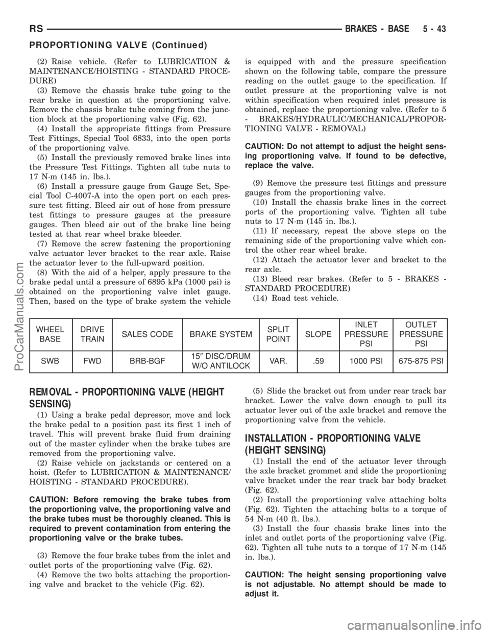
(8) With the aid of a helper, apply pressure to the
brake pedal until a pressure of 6895 kPa (1000 psi) is
obtained on the proportioning valve inlet gauge.
Then, based on the type of brake system the vehicleis equipped with and the pressure specification
shown on the following table, compare the pressure
reading on the outlet gauge to the specification. If
outlet pressure at the proportioning valve is not
within specification when required inlet pressure is
obtained, replace the proportioning valve. (Refer to 5
- BRAKES/HYDRAULIC/MECHANICAL/PROPOR-
TIONING VALVE - REMOVAL)
CAUTION: Do not attempt to adjust the height sens-
ing proportioning valve. If found to be defective,
replace the valve.
(9) Remove the pressure test fittings and pressure
gauges from the proportioning valve.
(10) Install the chassis brake lines in the correct
ports of the proportioning valve. Tighten all tube
nuts to 17 N´m (145 in. lbs.).
(11) If necessary, repeat the above steps on the
remaining side of the proportioning valve which con-
trol the other rear wheel brake.
(12) Attach the actuator lever and bracket to the
rear axle.
(13) Bleed rear brakes. (Refer to 5 - BRAKES -
STANDARD PROCEDURE)
(14) Road test vehicle.
WHEEL
BASEDRIVE
TRAINSALES CODE BRAKE SYSTEMSPLIT
POINTSLOPEINLET
PRESSURE
PSIOUTLET
PRESSURE
PSI
SWB FWD BRB-BGF159DISC/DRUM
W/O ANTILOCKVAR. .59 1000 PSI 675-875 PSI
REMOVAL - PROPORTIONING VALVE (HEIGHT
SENSING)
(1) Using a brake pedal depressor, move and lock
the brake pedal to a position past its first 1 inch of
travel. This will prevent brake fluid from draining
out of the master cylinder when the brake tubes are
removed from the proportioning valve.
(2) Raise vehicle on jackstands or centered on a
hoist. (Refer to LUBRICATION & MAINTENANCE/
HOISTING - STANDARD PROCEDURE).
CAUTION: Before removing the brake tubes from
the proportioning valve, the proportioning valve and
the brake tubes must be thoroughly cleaned. This is
required to prevent contamination from entering the
proportioning valve or the brake tubes.
(3) Remove the four brake tubes from the inlet and
outlet ports of the proportioning valve (Fig. 62).
(4) Remove the two bolts attaching the proportion-
ing valve and bracket to the vehicle (Fig. 62).(5) Slide the bracket out from under rear track bar
bracket. Lower the valve down enough to pull its
actuator lever out of the axle bracket and remove the
proportioning valve from the vehicle.
INSTALLATION - PROPORTIONING VALVE
(HEIGHT SENSING)
(1) Install the end of the actuator lever through
the axle bracket grommet and slide the proportioning
valve bracket under the rear track bar body bracket
(Fig. 62).
(2) Install the proportioning valve attaching bolts
(Fig. 62). Tighten the attaching bolts to a torque of
54 N´m (40 ft. lbs.).
(3) Install the four chassis brake lines into the
inlet and outlet ports of the proportioning valve (Fig.
62). Tighten all tube nuts to a torque of 17 N´m (145
in. lbs.).
CAUTION: The height sensing proportioning valve
is not adjustable. No attempt should be made to
adjust it.
RSBRAKES - BASE5-43
PROPORTIONING VALVE (Continued)
ProCarManuals.com
Page 205 of 2321
must be replaced. (Refer to 2 - SUSPENSION/
FRONT/HUB / BEARING - REMOVAL).
If the hub runout does not exceed this specifica-
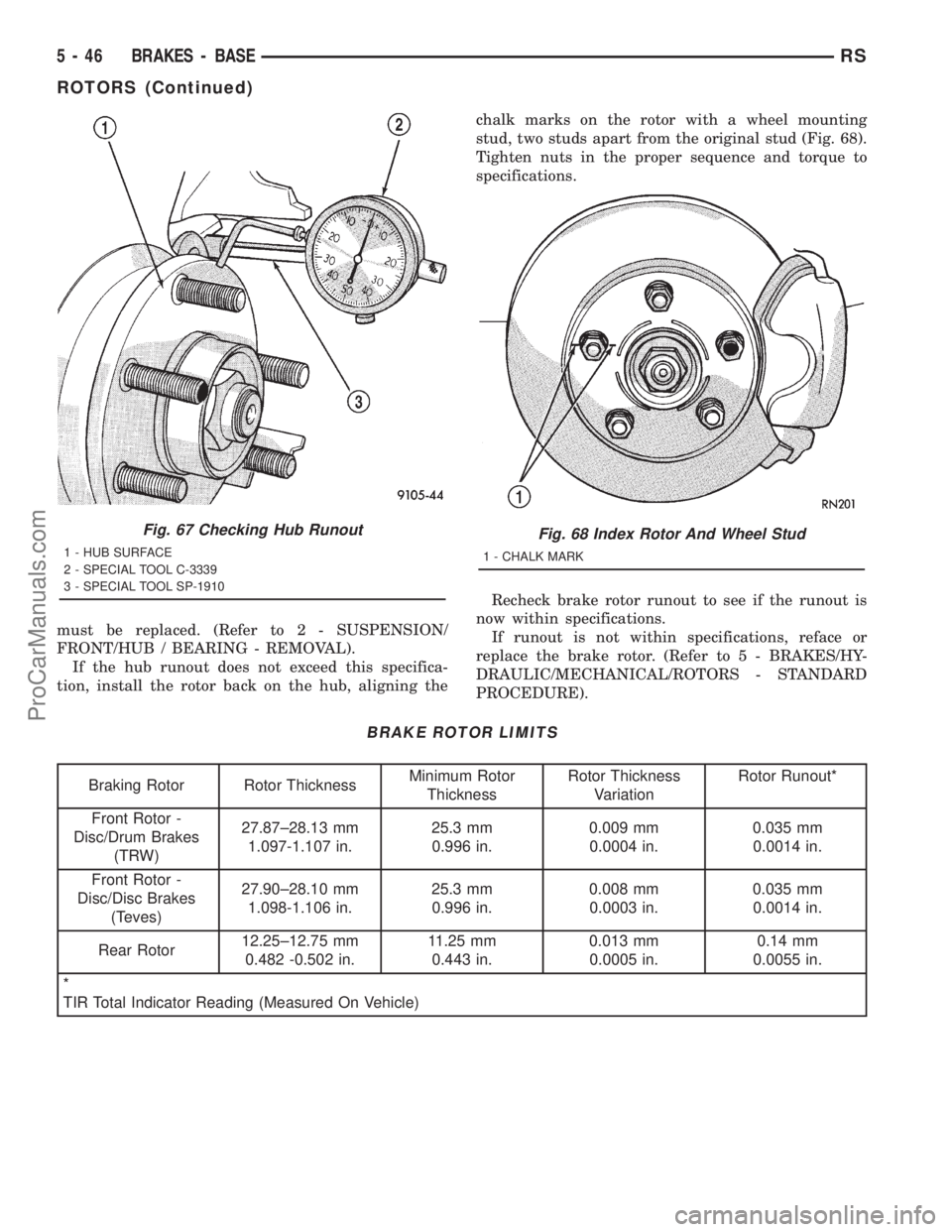
tion, install the rotor back on the hub, aligning thechalk marks on the rotor with a wheel mounting
stud, two studs apart from the original stud (Fig. 68).
Tighten nuts in the proper sequence and torque to
specifications.
Recheck brake rotor runout to see if the runout is
now within specifications.
If runout is not within specifications, reface or
replace the brake rotor. (Refer to 5 - BRAKES/HY-
DRAULIC/MECHANICAL/ROTORS - STANDARD
PROCEDURE).
BRAKE ROTOR LIMITS
Braking Rotor Rotor ThicknessMinimum Rotor
ThicknessRotor Thickness
VariationRotor Runout*
Front Rotor -
Disc/Drum Brakes
(TRW)27.87±28.13 mm
1.097-1.107 in.25.3 mm
0.996 in.0.009 mm
0.0004 in.0.035 mm
0.0014 in.
Front Rotor -
Disc/Disc Brakes
(Teves)27.90±28.10 mm
1.098-1.106 in.25.3 mm
0.996 in.0.008 mm
0.0003 in.0.035 mm
0.0014 in.
Rear Rotor12.25±12.75 mm
0.482 -0.502 in.11.25 mm
0.443 in.0.013 mm
0.0005 in.0.14 mm
0.0055 in.
*
TIR Total Indicator Reading (Measured On Vehicle)
Fig. 67 Checking Hub Runout
1 - HUB SURFACE
2 - SPECIAL TOOL C-3339
3 - SPECIAL TOOL SP-1910
Fig. 68 Index Rotor And Wheel Stud
1 - CHALK MARK
5 - 46 BRAKES - BASERS
ROTORS (Continued)
ProCarManuals.com
Page 207 of 2321
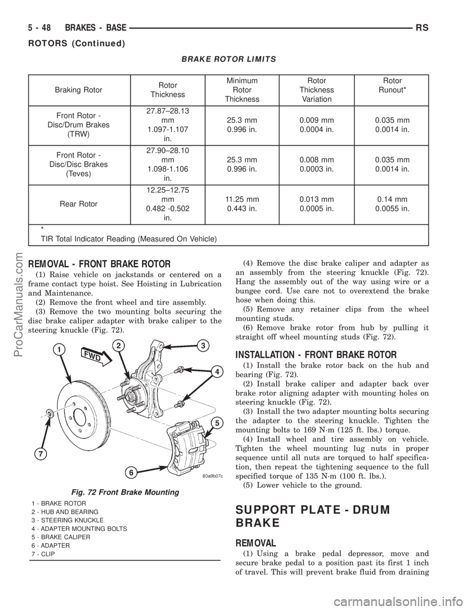
BRAKE ROTOR LIMITS
Braking RotorRotor
ThicknessMinimum
Rotor
ThicknessRotor
Thickness
VariationRotor
Runout*
Front Rotor -
Disc/Drum Brakes
(TRW)27.87±28.13
mm
1.097-1.107
in.25.3 mm
0.996 in.0.009 mm
0.0004 in.0.035 mm
0.0014 in.
Front Rotor -
Disc/Disc Brakes
(Teves)27.90±28.10
mm
1.098-1.106
in.25.3 mm
0.996 in.0.008 mm
0.0003 in.0.035 mm
0.0014 in.
Rear Rotor12.25±12.75
mm
0.482 -0.502
in.11.25 mm
0.443 in.0.013 mm
0.0005 in.0.14 mm
0.0055 in.
*
TIR Total Indicator Reading (Measured On Vehicle)
REMOVAL - FRONT BRAKE ROTOR
(1) Raise vehicle on jackstands or centered on a
frame contact type hoist. See Hoisting in Lubrication
and Maintenance.
(2) Remove the front wheel and tire assembly.
(3) Remove the two mounting bolts securing the
disc brake caliper adapter with brake caliper to the
steering knuckle (Fig. 72).(4) Remove the disc brake caliper and adapter as
an assembly from the steering knuckle (Fig. 72).
Hang the assembly out of the way using wire or a
bungee cord. Use care not to overextend the brake
hose when doing this.
(5) Remove any retainer clips from the wheel
mounting studs.
(6) Remove brake rotor from hub by pulling it
straight off wheel mounting studs (Fig. 72).
INSTALLATION - FRONT BRAKE ROTOR
(1) Install the brake rotor back on the hub and
bearing (Fig. 72).
(2) Install brake caliper and adapter back over
brake rotor aligning adapter with mounting holes on
steering knuckle (Fig. 72).
(3) Install the two adapter mounting bolts securing
the adapter to the steering knuckle. Tighten the
mounting bolts to 169 N´m (125 ft. lbs.) torque.
(4) Install wheel and tire assembly on vehicle.
Tighten the wheel mounting lug nuts in proper
sequence until all nuts are torqued to half specifica-
tion, then repeat the tightening sequence to the full
specified torque of 135 N´m (100 ft. lbs.).
(5) Lower vehicle to the ground.
SUPPORT PLATE - DRUM
BRAKE
REMOVAL
(1) Using a brake pedal depressor, move and
secure brake pedal to a position past its first 1 inch
of travel. This will prevent brake fluid from draining
Fig. 72 Front Brake Mounting
1 - BRAKE ROTOR
2 - HUB AND BEARING
3 - STEERING KNUCKLE
4 - ADAPTER MOUNTING BOLTS
5 - BRAKE CALIPER
6 - ADAPTER
7 - CLIP
5 - 48 BRAKES - BASERS
ROTORS (Continued)
ProCarManuals.com
Page 208 of 2321
out of master cylinder when brake tube is remove
from wheel cylinder.
(2) Raise vehicle. (Refer to LUBRICATION &
MAINTENANCE/HOISTING - STANDARD PROCE-
DURE).
(3) Remove wheel and tire assembly.
(4) Disconnect brake tube from rear of wheel cylin-
der. Cap open ends
(5) Remove brake drum.
(6) Remove brake shoes from brake support plate.
(Refer to 5 - BRAKES/HYDRAULIC/MECHANICAL/
BRAKE PADS/SHOES - REMOVAL).
(7) Remove the 2 bolts attaching the wheel cylin-
der to the brake support plate.
(8) Remove the wheel cylinder from the brake sup-
port plate.
(9) Disconnect the park brake cable from the park
brake actuation lever.
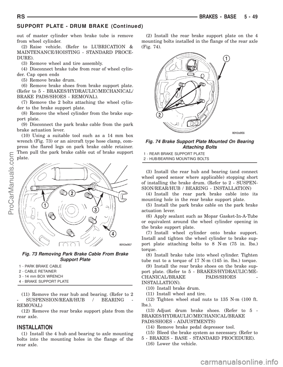
(10) Using a suitable tool such as a 14 mm box
wrench (Fig. 73) or an aircraft type hose clamp, com-
press the flared legs on park brake cable retainer.
Then pull the park brake cable out of brake support
plate.
(11) Remove the rear hub and bearing. (Refer to 2
- SUSPENSION/REAR/HUB / BEARING -
REMOVAL)
(12) Remove the rear brake support plate from the
rear axle.
INSTALLATION
(1) Install the 4 hub and bearing to axle mounting
bolts into the mounting holes in the flange of the
rear axle.(2) Install the rear brake support plate on the 4
mounting bolts installed in the flange of the rear axle
(Fig. 74).
(3) Install the rear hub and bearing (and connect
wheel speed sensor where applicable) stopping short
of installing the brake drum. (Refer to 2 - SUSPEN-
SION/REAR/HUB / BEARING - INSTALLATION)
(4) Install the rear park brake cable into its
mounting hole in the rear brake support plate.
(5) Install the park brake cable on the park brake
actuation lever.
(6) Apply sealant such as Mopar Gasket-In-A-Tube
or equivalent around the wheel cylinder opening in
the brake support plate.
(7) Install wheel cylinder onto brake support.
Install and tighten the wheel cylinder to brake sup-
port plate attaching bolts to 8 N´m (75 in. lbs.)
torque.
(8) Install brake tube into wheel cylinder. Tighten
tube nut to a torque of 17 N´m (145 in. lbs.) torque.
(9) Install the rear brake shoes on the brake sup-
port plate. (Refer to 5 - BRAKES/HYDRAULIC/ME-
CHANICAL/BRAKE PADS/SHOES -
INSTALLATION).
(10) Install brake drum.
(11) Install wheel and tire.
(12) Tighten wheel stud nuts to 135 N´m (100 ft.
lbs.).
(13) Adjust drum brake shoes. (Refer to 5 -
BRAKES/HYDRAULIC/MECHANICAL/BRAKE
PADS/SHOES - ADJUSTMENTS)
(14) Remove brake pedal depressor tool.
(15) Bleed the brake system as necessary. (Refer to
5 - BRAKES - BASE - STANDARD PROCEDURE).
(16) Lower the vehicle.
Fig. 73 Removing Park Brake Cable From Brake
Support Plate
1 - PARK BRAKE CABLE
2 - CABLE RETAINER
3 - 14 mm BOX WRENCH
4 - BRAKE SUPPORT PLATE
Fig. 74 Brake Support Plate Mounted On Bearing
Attaching Bolts
1 - REAR BRAKE SUPPORT PLATE
2 - HUB/BEARING MOUNTING BOLTS
RSBRAKES - BASE5-49
SUPPORT PLATE - DRUM BRAKE (Continued)
ProCarManuals.com