hood open DODGE TOWN AND COUNTRY 2001 Service Manual
[x] Cancel search | Manufacturer: DODGE, Model Year: 2001, Model line: TOWN AND COUNTRY, Model: DODGE TOWN AND COUNTRY 2001Pages: 2321, PDF Size: 68.09 MB
Page 296 of 2321
REMOVAL
There are no repairs to be made to the fan or
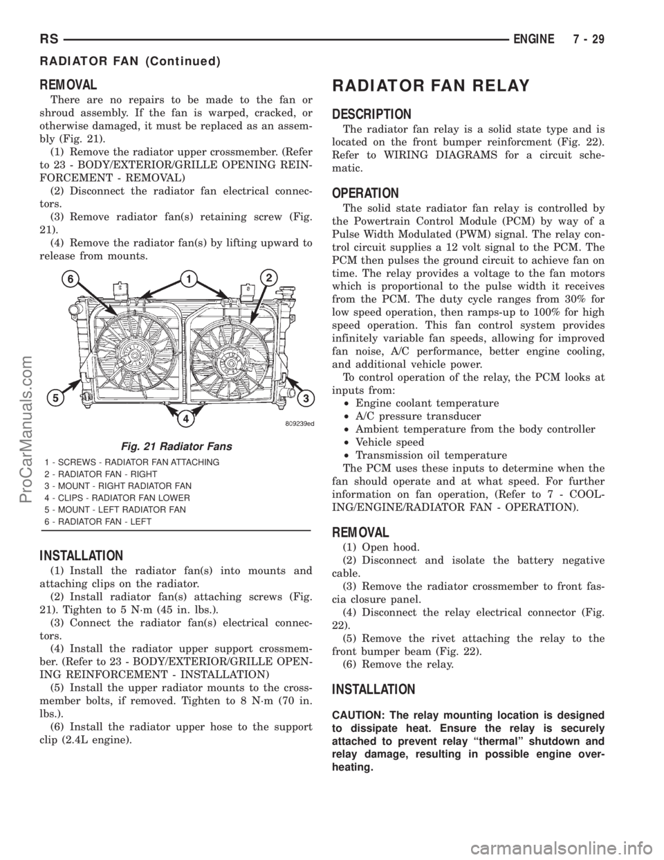
shroud assembly. If the fan is warped, cracked, or
otherwise damaged, it must be replaced as an assem-
bly (Fig. 21).
(1) Remove the radiator upper crossmember. (Refer
to 23 - BODY/EXTERIOR/GRILLE OPENING REIN-
FORCEMENT - REMOVAL)
(2) Disconnect the radiator fan electrical connec-
tors.
(3) Remove radiator fan(s) retaining screw (Fig.
21).
(4) Remove the radiator fan(s) by lifting upward to
release from mounts.
INSTALLATION
(1) Install the radiator fan(s) into mounts and
attaching clips on the radiator.
(2) Install radiator fan(s) attaching screws (Fig.
21). Tighten to 5 N´m (45 in. lbs.).
(3) Connect the radiator fan(s) electrical connec-
tors.
(4) Install the radiator upper support crossmem-
ber. (Refer to 23 - BODY/EXTERIOR/GRILLE OPEN-
ING REINFORCEMENT - INSTALLATION)
(5) Install the upper radiator mounts to the cross-
member bolts, if removed. Tighten to 8 N´m (70 in.
lbs.).
(6) Install the radiator upper hose to the support
clip (2.4L engine).
RADIATOR FAN RELAY
DESCRIPTION
The radiator fan relay is a solid state type and is
located on the front bumper reinforcment (Fig. 22).
Refer to WIRING DIAGRAMS for a circuit sche-
matic.
OPERATION
The solid state radiator fan relay is controlled by
the Powertrain Control Module (PCM) by way of a
Pulse Width Modulated (PWM) signal. The relay con-
trol circuit supplies a 12 volt signal to the PCM. The
PCM then pulses the ground circuit to achieve fan on
time. The relay provides a voltage to the fan motors
which is proportional to the pulse width it receives
from the PCM. The duty cycle ranges from 30% for
low speed operation, then ramps-up to 100% for high
speed operation. This fan control system provides
infinitely variable fan speeds, allowing for improved
fan noise, A/C performance, better engine cooling,
and additional vehicle power.
To control operation of the relay, the PCM looks at
inputs from:
²Engine coolant temperature
²A/C pressure transducer
²Ambient temperature from the body controller
²Vehicle speed
²Transmission oil temperature
The PCM uses these inputs to determine when the
fan should operate and at what speed. For further
information on fan operation, (Refer to 7 - COOL-
ING/ENGINE/RADIATOR FAN - OPERATION).
REMOVAL
(1) Open hood.
(2) Disconnect and isolate the battery negative
cable.
(3) Remove the radiator crossmember to front fas-
cia closure panel.
(4) Disconnect the relay electrical connector (Fig.
22).
(5) Remove the rivet attaching the relay to the
front bumper beam (Fig. 22).
(6) Remove the relay.
INSTALLATION
CAUTION: The relay mounting location is designed
to dissipate heat. Ensure the relay is securely
attached to prevent relay ªthermalº shutdown and
relay damage, resulting in possible engine over-
heating.
Fig. 21 Radiator Fans
1 - SCREWS - RADIATOR FAN ATTACHING
2 - RADIATOR FAN - RIGHT
3 - MOUNT - RIGHT RADIATOR FAN
4 - CLIPS - RADIATOR FAN LOWER
5 - MOUNT - LEFT RADIATOR FAN
6 - RADIATOR FAN - LEFT
RSENGINE7-29
RADIATOR FAN (Continued)
ProCarManuals.com
Page 323 of 2321
STANDARD PROCEDURE - COOLANT LEVEL
CHECK
NOTE: Do not remove pressure/vent cap for routine
coolant level inspections.
The coolant reserve system provides a quick visual
method for determining the coolant level without
removing the pressure/vent cap.With the engine
cold and not running,simply observe the level of
the coolant in the coolant recovery pressure container
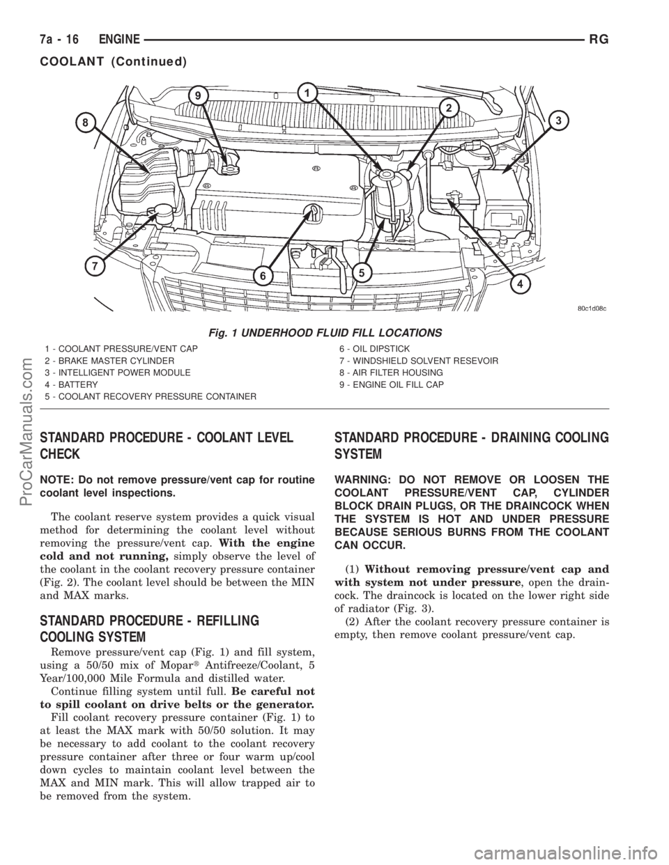
(Fig. 2). The coolant level should be between the MIN
and MAX marks.
STANDARD PROCEDURE - REFILLING
COOLING SYSTEM
Remove pressure/vent cap (Fig. 1) and fill system,
using a 50/50 mix of MopartAntifreeze/Coolant, 5
Year/100,000 Mile Formula and distilled water.
Continue filling system until full.Be careful not
to spill coolant on drive belts or the generator.
Fill coolant recovery pressure container (Fig. 1) to
at least the MAX mark with 50/50 solution. It may
be necessary to add coolant to the coolant recovery
pressure container after three or four warm up/cool
down cycles to maintain coolant level between the
MAX and MIN mark. This will allow trapped air to
be removed from the system.
STANDARD PROCEDURE - DRAINING COOLING
SYSTEM
WARNING: DO NOT REMOVE OR LOOSEN THE
COOLANT PRESSURE/VENT CAP, CYLINDER
BLOCK DRAIN PLUGS, OR THE DRAINCOCK WHEN
THE SYSTEM IS HOT AND UNDER PRESSURE
BECAUSE SERIOUS BURNS FROM THE COOLANT
CAN OCCUR.
(1)Without removing pressure/vent cap and
with system not under pressure, open the drain-
cock. The draincock is located on the lower right side
of radiator (Fig. 3).
(2) After the coolant recovery pressure container is
empty, then remove coolant pressure/vent cap.
Fig. 1 UNDERHOOD FLUID FILL LOCATIONS
1 - COOLANT PRESSURE/VENT CAP
2 - BRAKE MASTER CYLINDER
3 - INTELLIGENT POWER MODULE
4 - BATTERY
5 - COOLANT RECOVERY PRESSURE CONTAINER6 - OIL DIPSTICK
7 - WINDSHIELD SOLVENT RESEVOIR
8 - AIR FILTER HOUSING
9 - ENGINE OIL FILL CAP
7a - 16 ENGINERG
COOLANT (Continued)
ProCarManuals.com
Page 410 of 2321
SPECIAL TOOLS
SPECIAL TOOLS
BATTERY TEMPERATURE
SENSOR
DESCRIPTION
The PCM incorporates a Battery Temperature Sen-
sor (BTS) on its circuit board.
OPERATION
The PCM uses the temperature of the battery area
to control the charge rate. This temperature data,
along with data from monitored line voltage, is used
by the PCM to vary the battery charging rate. The
system voltage is higher at cold temperatures and is
gradually reduced as temperature around the battery
increases.
The function of the battery temperature sensor
(BTS) is to enable control of the generator output
based upon ambient battery temperature. As battery
temperature increases, the charging rate should
decrease. As battery temperature decreases, the
charging rate should increase. The sensor functions
similar to the ECT sensor with one major difference,
the ambient sensor does not have a dual temperature
range program. The PCM maintains the optimal out-
put of the generator by monitoring battery voltage
and controlling battery voltage to a range of
13.5-14.7 volts based on battery temperature.
The battery temperature sensor is also used for
OBD II diagnostics. Certain faults and OBD II mon-
itors are either enabled or disabled depending upon
the battery temperature sensor input (example: dis-
able purge and EGR, enable LDP). Most OBD II
monitors are disabled below 20ÉF.
REMOVAL
The battery temperature sensor is not a serviced
separately. If replacement is necessary, the PCM
must be replaced.
GENERATOR
DESCRIPTION
The generator is belt-driven by the engine. It is
serviced only as a complete assembly. The generator
produces DC voltage at the B+ terminal. If the gen-
erator is failed, the generator assembly subcompo-
nents (generator and decoupler pulley) must be
inspected for individual failure and replaced accord-
ingly.
OPERATION
As the energized rotor begins to rotate within the
generator, the spinning magnetic field induces a cur-
rent into the windings of the stator coil. Once the
generator begins producing sufficient current, it also
provides the current needed to energize the rotor.
The Y type stator winding connections deliver the
induced AC current to 3 positive and 3 negative
diodes for rectification. From the diodes, rectified DC
current is delivered to the vehicles electrical system
through the generator, battery, and ground terminals.
Noise emitting from the generator may be caused
by:
²Worn, loose or defective bearings
²Loose or defective drive pulley (2.4L) or decou-
pler (3.3/3.8L)
²Incorrect, worn, damaged or misadjusted drive
belt
²Loose mounting bolts
²Misaligned drive pulley
²Defective stator or diode
²Damaged internal fins
REMOVAL - 2.4L
(1) Release hood latch and open hood.
(2) Disconnect battery negative cable.
(3) Disconnect the Inlet Air Temperature sensor.
(4) Remove the Air Box, refer to the Engine/Air
Cleaner for more information.
(5) Remove the EVAP Purge solenoid from its
bracket and reposition.
(6) Disconnect the push-in field wire connector
from back of generator.
(7) Remove nut holding B+ wire terminal to back
of generator.
(8) Separate B+ terminal from generator.
(9) Remove accessory drive belt, refer to the Cool-
ing System section for proper procedures.
(10) Remove the generator.
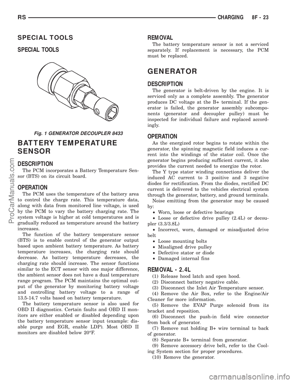
Fig. 1 GENERATOR DECOUPLER 8433
RSCHARGING8F-23
ProCarManuals.com
Page 411 of 2321
REMOVAL - 3.3/3.8L
(1) Release hood latch and open hood.
(2) Disconnect battery negative cable.
(3) Disconnect the push-in field wire connector
from back of generator.
(4) Remove nut holding B+ wire terminal to back
of generator.
(5) Separate B+ terminal from generator.
(6) Raise vehicle and support.
(7) Remove the right front lower splash shield.
(8) Remove accessory drive belt, refer to the Cool-
ing System section for proper procedures.
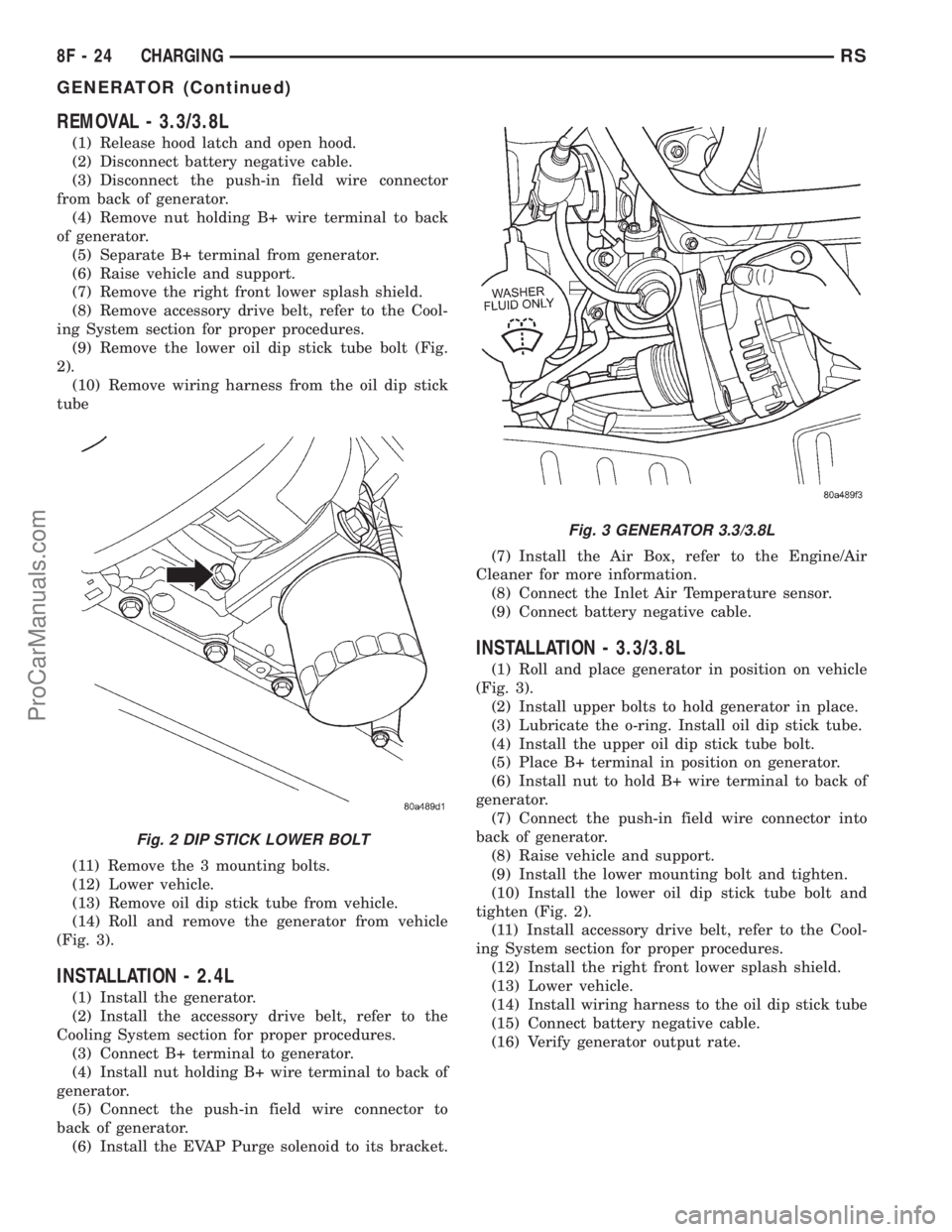
(9) Remove the lower oil dip stick tube bolt (Fig.
2).
(10) Remove wiring harness from the oil dip stick
tube
(11) Remove the 3 mounting bolts.
(12) Lower vehicle.
(13) Remove oil dip stick tube from vehicle.
(14) Roll and remove the generator from vehicle
(Fig. 3).
INSTALLATION - 2.4L
(1) Install the generator.
(2) Install the accessory drive belt, refer to the
Cooling System section for proper procedures.
(3) Connect B+ terminal to generator.
(4) Install nut holding B+ wire terminal to back of
generator.
(5) Connect the push-in field wire connector to
back of generator.
(6) Install the EVAP Purge solenoid to its bracket.(7) Install the Air Box, refer to the Engine/Air
Cleaner for more information.
(8) Connect the Inlet Air Temperature sensor.
(9) Connect battery negative cable.
INSTALLATION - 3.3/3.8L
(1) Roll and place generator in position on vehicle
(Fig. 3).
(2) Install upper bolts to hold generator in place.
(3) Lubricate the o-ring. Install oil dip stick tube.
(4) Install the upper oil dip stick tube bolt.
(5) Place B+ terminal in position on generator.
(6) Install nut to hold B+ wire terminal to back of
generator.
(7) Connect the push-in field wire connector into
back of generator.
(8) Raise vehicle and support.
(9) Install the lower mounting bolt and tighten.
(10) Install the lower oil dip stick tube bolt and
tighten (Fig. 2).
(11) Install accessory drive belt, refer to the Cool-
ing System section for proper procedures.
(12) Install the right front lower splash shield.
(13) Lower vehicle.
(14) Install wiring harness to the oil dip stick tube
(15) Connect battery negative cable.
(16) Verify generator output rate.
Fig. 2 DIP STICK LOWER BOLT
Fig. 3 GENERATOR 3.3/3.8L
8F - 24 CHARGINGRS
GENERATOR (Continued)
ProCarManuals.com
Page 412 of 2321
GENERATOR DECOUPLER
PULLEY
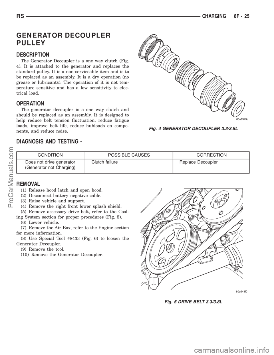
DESCRIPTION
The Generator Decoupler is a one way clutch (Fig.
4). It is attached to the generator and replaces the
standard pulley. It is a non-serviceable item and is to
be replaced as an assembly. It is a dry operation (no
grease or lubricants). The operation of it is not tem-
perature sensitive and has a low sensitivity to elec-
trical load.
OPERATION
The generator decoupler is a one way clutch and
should be replaced as an assembly. It is designed to
help reduce belt tension fluctuation, reduce fatigue
loads, improve belt life, reduce hubloads on compo-
nents, and reduce noise.
DIAGNOSIS AND TESTING -
CONDITION POSSIBLE CAUSES CORRECTION
Does not drive generator
(Generator not Charging)Clutch failure Replace Decoupler
REMOVAL
(1) Release hood latch and open hood.
(2) Disconnect battery negative cable.
(3) Raise vehicle and support.
(4) Remove the right front lower splash shield.
(5) Remove accessory drive belt, refer to the Cool-
ing System section for proper procedures (Fig. 5).
(6) Lower vehicle.
(7) Remove the Air Box, refer to the Engine section
for more information.
(8) Use Special Tool #8433 (Fig. 6) to loosen the
Generator Decoupler.
(9) Remove the tool.
(10) Remove the Generator Decoupler.
Fig. 4 GENERATOR DECOUPLER 3.3/3.8L
Fig. 5 DRIVE BELT 3.3/3.8L
RSCHARGING8F-25
ProCarManuals.com
Page 420 of 2321
STARTER MOTOR
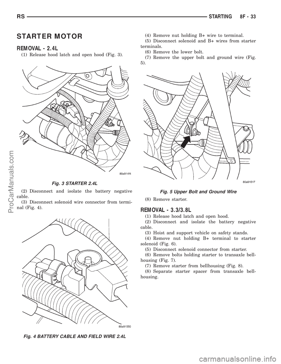
REMOVAL - 2.4L
(1) Release hood latch and open hood (Fig. 3).
(2) Disconnect and isolate the battery negative
cable.
(3) Disconnect solenoid wire connector from termi-
nal (Fig. 4).(4) Remove nut holding B+ wire to terminal.
(5) Disconnect solenoid and B+ wires from starter
terminals.
(6) Remove the lower bolt.
(7) Remove the upper bolt and ground wire (Fig.
5).
(8) Remove starter.
REMOVAL - 3.3/3.8L
(1) Release hood latch and open hood.
(2) Disconnect and isolate the battery negative
cable.
(3) Hoist and support vehicle on safety stands.
(4) Remove nut holding B+ terminal to starter
solenoid (Fig. 6).
(5) Disconnect solenoid connector from starter.
(6) Remove bolts holding starter to transaxle bell-
housing (Fig. 7).
(7) Remove starter from bellhousing (Fig. 8).
(8) Separate starter spacer from transaxle bell-
housing.
Fig. 3 STARTER 2.4L
Fig. 4 BATTERY CABLE AND FIELD WIRE 2.4L
Fig. 5 Upper Bolt and Ground Wire
RSSTARTING8F-33
ProCarManuals.com
Page 505 of 2321
more faulty electronic modules in the vehicle, or from
a faulty PCI data bus. The use of a DRB IIItscan
tool and the proper Diagnostic Procedures manual
are required for further diagnosis.
NOTE: If the compass functions, but accuracy is
suspect, it may be necessary to perform a variation
adjustment. This procedure allows the compass
unit to accommodate variations in the earth's mag-
netic field strength, based on geographic location.
Refer to Compass Variation Adjustment in the Ser-
vice Procedures section of this group.
NOTE: If the compass reading displays dashes, and
only ªCALº appears in the display, demagnetizing
may be necessary to remove excessive residual
magnetic fields from the vehicle. Refer to Compass
Demagnetizing in the Service Procedures section of
this group.
STANDARD PROCEDURE - READING/
COURTESY LAMP REPLACEMENT
(1) Open hood, disconnect and isolate the negative
battery cable remote terminal from the remote bat-
tery post.
(2) Remove the reading/courtesy lamp lens. Using
a trim stick, gently pry the forward edge of the read-
ing/courtesy lamp lens outward.
(3) Remove the reading/courtesy lamp socket from
the overhead console. Rotate the reading/courtesy
lamp socket one quarter turn counter clockwise.
(4) Remove the lamp and socket assembly.
(5) Reverse the above procedure to install.
STANDARD PROCEDURE - COMPASS
CALIBRATION
CAUTION: Do not place any external magnets, such
as magnetic roof mount antennas, in the vicinity of
the compass. Do not use magnetic tools when ser-
vicing the overhead console.
The electronic compass unit features a self-cali-
brating design, which simplifies the calibration pro-
cedure. This feature automatically updates the
compass calibration while the vehicle is being driven.
This allows the compass unit to compensate for small
changes in the residual magnetism that the vehicle
may acquire during normal use. If the compass read-
ings appear to be erratic or out of calibration, per-
form the following calibration procedure. Also, new
service replacement Electronic Modules (EVIC,
CMTC, CT) must have their compass calibrated
using this procedure. Do not attempt to calibrate the
compass near large metal objects such as other vehi-cles, large buildings, or bridges; or, near overhead or
underground power lines.
NOTE: Whenever the compass is calibrated manu-
ally, the variance number must also be reset. Refer
to Compass Variation Adjustment in this group.
Calibrate the compass manually as follows:
(1) Turn the ignition switch to the On position. If
the compass/thermometer data is not currently being
displayed, momentarily depress and release the C/T
push button to reach the compass/thermometer dis-
play.
(2) On Electronic Vehicle Information Center
(EVIC) and Compass Mini-Trip Computer (CMTC)
equipped vehicles depress the Reset push button and
hold the button down until ªCALº appears in the dis-
play. This takes about ten seconds, and appears
about five seconds after ªVAR = XXº is displayed. On
Compass Temperature Module (CT) equipped vehicles
depress the C/T push button and US/M push button
down until ªCALº appears in the display. This takes
about ten seconds, and appears about five seconds
after ªVAR = XXº is displayed.
(3) Release the push button(s).
(4) Drive the vehicle on a level surface, away from
large metal objects and power lines, through three or
more complete circles at between five and eight kilo-
meters-per-hour (three and five miles-per-hour) in
not less than 48 seconds. The ªCALº message will
disappear from the display to indicate that the com-
pass is now calibrated.
NOTE: If the ªCALº message remains in the display,
either there is excessive magnetism near the com-
pass, or the unit is faulty. Repeat the calibration
procedure one more time.
NOTE: If the wrong direction is still indicated in the
compass display, the area selected for calibration
may be too close to a strong magnetic field. Repeat
the calibration procedure in another location.
STANDARD PROCEDURE - COMPASS
DEMAGNETIZING
A degaussing tool (Special Tool 6029) is used to
demagnetize, or degauss, the overhead console for-
ward mounting screw and the roof panel above the
overhead console. Equivalent units must be rated as
continuous duty for 110/115 volts and 60 Hz. They
must also have a field strength of over 350 gauss at 7
millimeters (0.25 inch) beyond the tip of the probe.
To demagnetize the roof panel and the overhead
console forward mounting screw, proceed as follows:
8M - 4 OVERHEAD CONSOLERS
OVERHEAD CONSOLE (Continued)
ProCarManuals.com
Page 528 of 2321
LATCH
DESCRIPTION
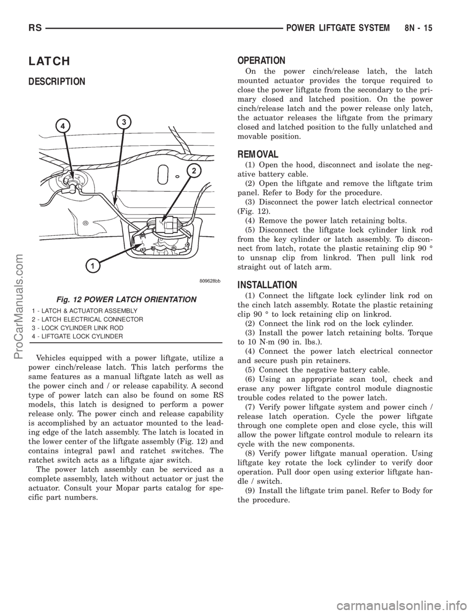
Vehicles equipped with a power liftgate, utilize a
power cinch/release latch. This latch performs the
same features as a manual liftgate latch as well as
the power cinch and / or release capability. A second
type of power latch can also be found on some RS
models, this latch is designed to perform a power
release only. The power cinch and release capability
is accomplished by an actuator mounted to the lead-
ing edge of the latch assembly. The latch is located in
the lower center of the liftgate assembly (Fig. 12) and
contains integral pawl and ratchet switches. The
ratchet switch acts as a liftgate ajar switch.
The power latch assembly can be serviced as a
complete assembly, latch without actuator or just the
actuator. Consult your Mopar parts catalog for spe-
cific part numbers.
OPERATION
On the power cinch/release latch, the latch
mounted actuator provides the torque required to
close the power liftgate from the secondary to the pri-
mary closed and latched position. On the power
cinch/release latch and the power release only latch,
the actuator releases the liftgate from the primary
closed and latched position to the fully unlatched and
movable position.
REMOVAL
(1) Open the hood, disconnect and isolate the neg-
ative battery cable.
(2) Open the liftgate and remove the liftgate trim
panel. Refer to Body for the procedure.
(3) Disconnect the power latch electrical connector
(Fig. 12).
(4) Remove the power latch retaining bolts.
(5) Disconnect the liftgate lock cylinder link rod
from the key cylinder or latch assembly. To discon-
nect from latch, rotate the plastic retaining clip 90 É
to unsnap clip from linkrod. Then pull link rod
straight out of latch arm.
INSTALLATION
(1) Connect the liftgate lock cylinder link rod on
the cinch latch assembly. Rotate the plastic retaining
clip 90 É to lock retaining clip on linkrod.
(2) Connect the link rod on the lock cylinder.
(3) Install the power latch retaining bolts. Torque
to 10 N´m (90 in. lbs.).
(4) Connect the power latch electrical connector
and secure push pin retainers.
(5) Connect the negative battery cable.
(6) Using an appropriate scan tool, check and
erase any power liftgate control module diagnostic
trouble codes related to the power latch.
(7) Verify power liftgate system and power cinch /
release latch operation. Cycle the power liftgate
through one complete open and close cycle, this will
allow the power liftgate control module to relearn its
cycle with the new components.
(8) Verify power liftgate manual operation. Using
liftgate key rotate the lock cylinder to verify door
operation. Pull door open using exterior liftgate han-
dle / switch.
(9) Install the liftgate trim panel. Refer to Body for
the procedure.Fig. 12 POWER LATCH ORIENTATION
1 - LATCH & ACTUATOR ASSEMBLY
2 - LATCH ELECTRICAL CONNECTOR
3 - LOCK CYLINDER LINK ROD
4 - LIFTGATE LOCK CYLINDER
RSPOWER LIFTGATE SYSTEM8N-15
ProCarManuals.com
Page 583 of 2321
(4) Remove steering wheel.
(5) Depress the two plastic locking pins to disen-
gage lock mechanism.
(6) With lock mechanism disengaged, rotate the
clock spring rotor clockwise until the rotor stops. Do
not apply excessive force.
(7) From the end of travel, rotate the rotor three
turns counterclockwise. The wires should end up at
the top. Release locking pins to engage clock spring
lock mechanism.
(8) Install steering wheel and airbag.
WARNING: DO NOT CONNECT THE BATTERY NEG-
ATIVE CABLE. REFER TO ELECTRICAL,
RESTRAINTS, DIAGNOSIS AND TESTING - AIRBAG
SYSTEM FIRST.
REMOVAL
(1) Position steering wheel and front wheels
straight ahead.
(2) Release hood latch and open hood. Disconnect
and isolate the battery negative cable.
(3) Remove driver airbag from steering wheel.
(4) Disconnect wire connectors from back of driver
airbag.
(5) Disconnect the 2±way connector from remote
radio control harness.
(6) Remove steering wheel.
(7) Remove steering column shrouds.
(8) Disconnect 2-way and 5-way connectors
between the clock spring and the instrument panel
wiring harness.
(9) Remove clock spring from housing assembly by
removing the two retaining screws retaining the
clock spring.
INSTALLATION
(1) Position the clock spring into the housing.
Install the two retaining screws to clock spring.
(2) Connect the two way and five way harness
between the clock spring and the instrument panel.
(3) Install the steering wheel. Refer to Steering,
Column, Steering Wheel, Installation.
(4) Connect the harness connector to the driver
airbag.
(5) Connect the remote radio control harness.
(6)
Install the driver airbag into the steering wheel.
(7) Install the steering column upper and lower
shrouds.
WARNING: DO NOT CONNECT THE BATTERY NEG-
ATIVE CABLE. REFER TO ELECTRICAL,
RESTRAINTS, DIAGNOSIS AND TESTING - AIRBAG
SYSTEM FIRST.
DRIVER AIRBAG
DESCRIPTION
The Driver Airbag is located in the center of the
steering wheel. The most visible part of the airbag is
the cover/horn switch.
OPERATION
The Driver Airbag cover contains the horn switch,
inflator device, and a fabric bag. The airbag cover/
horn switch is serviced separately from the inflator
and bag components.
WHEN THE FRONT AIRBAG SYSTEM IS
DEPLOYED BECAUSE OF A COLLISION, THE
FOLLOWING MUST BE REPLACED:
²COMPLETE STEERING COLUMN ASSEMBLY
²LOWER STEERING COUPLER
²STEERING WHEEL
²STEERING COLUMN CLOCK SPRING
²DRIVER AIRBAG
²PASSENGER AIRBAG
²UPPER INSTRUMENT PANEL WITH PAD
CARE OF UNDEPLOYED AIRBAGS
Airbags must be stored in their original special
container until used for service. At no time should a
source of electricity be permitted near the inflator on
the back of an airbag. When carrying or handling an
undeployed airbag, the trim side of the airbag should
be pointing away from the body to minimize possibil-
ity of injury if accidental deployment occurs. Do not
place undeployed airbag face down on a solid surface,
the airbag will propel into the air if accidental
deployment occurs.
STANDARD PROCEDURE - DEPLOYED DRIVER
AIRBAG CLEAN UP
Roll or fold the driver airbag towards the steering
wheel and then tape the bag to the steering wheel.
Use a vacuum cleaner to remove any residual pow-
der from the vehicle interior. Work from the outside
in to avoid kneeling or sitting in a contaminated
area. Vacuum the heater and A/C outlets as well. If
HVAC was in RECIRC mode at time of airbag
deployment, operate HVAC blower on low speed/heat
and vacuum powder residue expelled from the heat
outlets. Multiple vacuum cleaning may be necessary
to decontaminate the interior of the vehicle.
SERVICE OF DEPLOYED AIRBAG
If a Driver Airbag has been deployed, but not due
to a collision, replace the following:
²Driver Airbag
²Clock Spring Assembly
8O - 4 RESTRAINTSRS
CLOCK SPRING (Continued)
ProCarManuals.com
Page 594 of 2321
defective they must be replaced. After an airbag
deployment, the tensioner must be replaced.
OPERATION
At the onset of an impact event, each tensioner
uses a pyrotechnic device which is triggered simulta-
neously with the airbags to rapidly retract the seat
belts. With the slack removed, the occupant's forward
motion in an impact will be reduced as will the like-
lihood of contacting interior components. After an
impact that deploys the airbags, the seat belt ten-
sioner assembly must be replaced.
The Occupant Restraint Controller (ORC) monitors
the seat belt tensioner circuit resistance and reports
active and stored Diagnostic Trouble Codes (DTC's) if
any problem is found.
Once a vehicle has been in an accident, the tensioner
must be replaced along with any deployed airbags and
broken or damaged parts. Refer to the proper Body
Diagnostic Procedures manual for diagnosis and testing.
WARNING: WHEN THE FRONT AIRBAG IS
DEPLOYED, THE TENSIONER WILL HAVE
DEPLOYED ALSO AND SHOULD BE REPLACED.
SHOULDER BELT HEIGHT
ADJUSTER
REMOVAL
(1) Remove B or C-pillar trim cover.
(2) Remove screws attaching shoulder belt height
adjuster to pillar.
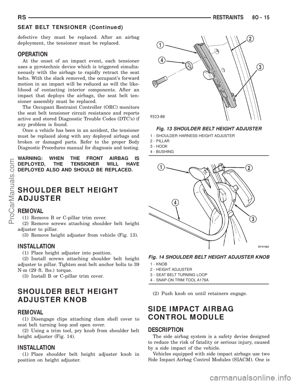
(3) Remove height adjuster from vehicle (Fig. 13).
INSTALLATION
(1) Place height adjuster into position.
(2) Install screws attaching shoulder belt height
adjuster to pillar. Tighten seat belt anchor bolts to 39
N´m (29 ft. lbs.) torque.
(3) Install B or C-pillar trim cover.
SHOULDER BELT HEIGHT
ADJUSTER KNOB
REMOVAL
(1) Disengage clips attaching clam shell cover to
seat belt turning loop and open cover.
(2) Using a trim tool, pry knob from shoulder belt
height adjuster (Fig. 14).
INSTALLATION
(1) Place shoulder belt height adjuster knob in
position on height adjuster.(2) Push knob on until retainers engage.
SIDE IMPACT AIRBAG
CONTROL MODULE
DESCRIPTION
The side airbag system is a safety devise designed
to reduce the risk of fatality or serious injury, caused
by a side impact of the vehicle.
Vehicles equipped with side impact airbags use two
Side Impact Airbag Control Modules (SIACM). One is
Fig. 13 SHOULDER BELT HEIGHT ADJUSTER
1 - SHOULDER HARNESS HEIGHT ADJUSTER
2 - PILLAR
3 - HOOK
4 - BUSHING
Fig. 14 SHOULDER BELT HEIGHT ADJUSTER KNOB
1 - KNOB
2 - HEIGHT ADJUSTER
3 - SEAT BELT TURNING LOOP
4 - SNAP-ON TRIM TOOL A179A
RSRESTRAINTS8O-15
SEAT BELT TENSIONER (Continued)
ProCarManuals.com