timing belt DODGE TOWN AND COUNTRY 2001 Service Manual
[x] Cancel search | Manufacturer: DODGE, Model Year: 2001, Model line: TOWN AND COUNTRY, Model: DODGE TOWN AND COUNTRY 2001Pages: 2321, PDF Size: 68.09 MB
Page 34 of 2321
²Inspect the generator belt on 2.4 liter engines
and replace if necessary.
²Inspect the serpentine drive belt on 3.3 liter and
3.8 liter engines. Not required if replaced at 75,000,
90,000 or 105,000 miles.
²Replace theengine timing belton 2.4 liter
engine only.
²Inspect the tie rod ends and boot seals.
* This maintenance is recommended by Daimler-
Chrysler Corporation to the owner but is not
required to maintain the emissions warranty.
Inspection and service should also be performed
anytime a malfunction is observed or suspected.
Retain all receipts.
SCHEDULE±B±DODGE VEHICLES, CHRYSLER
VOYAGER
Follow this schedule if the vehicle is usually oper-
ates under one or more of the following conditions.
²Frequent short trips of less than 5 miles
²Frequent driving in dusty conditions
²Frequent trailer towing
²Day and night temperatures are below freezing
²Frequent stop and go driving
²Extensive periods of idling
²Frequent operation at sustained high speeds
during hot weather, above 90ÉF (32ÉC)
²Use of E-85 (ethanol) fuel in 3.3 liter engines.
3,000 Miles (5 000 km)
²Change the engine oil.
²Replace the engine oil filter.
6,000 Miles (10 000 km)
²Change the engine oil.
²Replace the engine oil filter.
9,000 Miles (14 000 km)
²Change the engine oil.
²Replace the engine oil filter.
²Inspect the brake linings.
12,000 Miles (19 000 km)
²Change the engine oil.
²Replace the engine oil filter.
15,000 Miles (24 000 km)
²Change the engine oil.
²Replace the engine oil filter.
²Inspect theengine air cleaner element (fil-
ter).Replace as necessary.*
²Change the All Wheel Drive (AWD) power trans-
fer unit fluid. (See the note at the end of Schedule ±
B.)
²Inspect the generator belt on 2.4 liter engines
and replace if necessary.
18,000 Miles (29 000 km)
²Change the engine oil.
²Replace the engine oil filter.
²Inspect the brake linings.
21,000 Miles (34 000 km)
²Change the engine oil.
²Replace the engine oil filter.
²Change the All Wheel Drive (AWD) overrunning
clutch and rear carrier fluid. (See the note at the end
of Schedule ± B.)
24,000 Miles (38 000 km)
²Change the engine oil.
²Replace the engine oil filter.
27,000 Miles (43 000 km)
²Change the engine oil.
²Replace the engine oil filter.
²Inspect the brake linings.
30,000 Miles (48 000 km)
²Change the engine oil.
²Replace the engine oil filter.
²Replace theengine air cleaner element (fil-
ter).
²Inspect thePCV valveand replace as neces-
sary.*
²Replace thespark plugs2.4 liter engines.
²Inspect and adjust the generator belt and power
steering pump belt tension on 2.4 liter engines.
²Change the All Wheel Drive (AWD) power trans-
fer unit fluid. (See the note at the end of Schedule ±
B.)
²Inspect the tie rod ends and boot seals.
33,000 Miles (53 000 km)
²Change the engine oil.
²Replace the engine oil filter.
36,000 Miles (58 000 km)
²Change the engine oil.
²Replace the engine oil filter.
²Inspect the brake linings.
39,000 Miles (62 000 km)
²Change the engine oil.
²Replace the engine oil filter.
42,000 Miles (67 000 km)
²Change the engine oil.
²Replace the engine oil filter.
²Change the All Wheel Drive (AWD) overrunning
clutch and rear carrier fluid. (See the note at the end
of Schedule ± B.)
RSLUBRICATION & MAINTENANCE0-13
MAINTENANCE SCHEDULES (Continued)
ProCarManuals.com
Page 36 of 2321
²Check thePCV valveand replace if necessary.
Not required if previously changed.*
²Replace thespark plugson 2.4 liter engines.
²Inspect the generator belt on 2.4 liter engines
and replace if necessary.
²Inspect the serpentine drive belt (3.3 liter and
3.8 liter engines) and replace if necessary. This main-
tenance is not required if belt was previously
replaced.
²Change the All Wheel Drive (AWD) power trans-
fer unit fluid. (See the note at the end of Schedule ±
B.)
²Inspect the tie rod ends and boot seals.
²Inspect the brake linings.
93,000 Miles (149 000 km)
²Change the engine oil.
²Replace the engine oil filter.
96,000 Miles (154 000 km)
²Change the engine oil.
²Replace the engine oil filter.
²Drain and replace the automatic transmission
fluid and filter.
²Adjust bands on 3±speed transmission. (See the
note at the end of Schedule ± B.)
99,000 Miles (158 000 km)
²Change the engine oil.
²Replace the engine oil filter.
²Inspect the brake linings.
100,000 Miles (160 000 km)
²Flush and replace engine coolant at 60 months
or 100,000 miles (160 000 km).
102,000 Miles (163 000 km)
²Change the engine oil.
²Replace the engine oil filter.
105,000 Miles (168 000 km)
²Change the engine oil.
²Replace the engine oil filter.
²Inspect theengine air cleaner element (fil-
ter)and replace as necessary.*
²Inspect the generator belt on 2.4 liter engines
and replace if necessary.
²Inspect the serpentine drive belt on 3.3 liter and
3.8 liter engines and replace if necessary. This main-
tenance is not required if the belt was previously
replaced.
²Change the All Wheel Drive (AWD) power trans-
fer unit fluid. (See the note at the end of Schedule ±
B.)
²Change the All Wheel Drive (AWD) overrunning
clutch and rear carrier fluid. (See the note at the end
of Schedule ± B.)
108,000 Miles (173 000 km)
²Change the engine oil.
²Replace the engine oil filter.
²Inspect the brake linings.
111,000 Miles (178 000 km)
²Change the engine oil.
²Replace the engine oil filter.
114,000 Miles (182 000 km)
²Change the engine oil.
²Replace the engine oil filter.
117,000 Miles (187 000 km)
²Change the engine oil.
²Replace the engine oil filter.
²Inspect the brake linings.
120,000 Miles (192 000 km)
²Change the engine oil.
²Replace the engine oil filter.
²Replace theengine air cleaner element (fil-
ter).
²Inspect thePCV valveand replace as neces-
sary.*
²Replace thespark plugson 2.4 liter engines.
²Inspect the generator belt and power steering
pump belt tension, replace the belt if necessary on
2.4 liter engines.
²Inspect the serpentine drive belt on 3.3 liter and
3.8 liter engines. Not required if replaced at 75,000,
90,000 or 105,000 miles.
²Replace theengine timing belton 2.4 liter
engines.
²Change the All Wheel Drive (AWD) power trans-
fer unit fluid. (See the note at the end of Schedule ±
B.)
²Inspect the tie rod ends and boot seals.
* This maintenance is recommended by Daimler-
Chrysler Corporation to the owner but is not
required to maintain the emissions warranty.
NOTE: Operating the vehicle more than 50% in
heavy traffic during hot weather, above 90ÉF (32ÉC),
using vehicle for police, taxi, limousine type opera-
tion or trailer towing require the more frequent tran-
saxle service noted in Schedule ± B. Perform these
services if vehicle usually operate under these con-
ditions.
NOTE: The AWD power transfer unit fluid and the
AWD overrunning clutch/rear carrier fluid must be
changed at the more frequent intervals shown in
schedule B if the vehicle is operated under any of
the conditions noted by an asterisk at the begin-
ning of the schedule.
RSLUBRICATION & MAINTENANCE0-15
MAINTENANCE SCHEDULES (Continued)
ProCarManuals.com
Page 297 of 2321
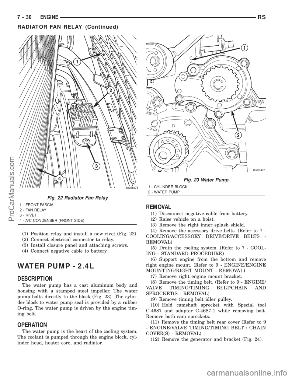
(1) Position relay and install a new rivet (Fig. 22).
(2) Connect electrical connector to relay.
(3) Install closure panel and attaching screws.
(4) Connect negative cable to battery.
WATER PUMP - 2.4L
DESCRIPTION
The water pump has a cast aluminum body and
housing with a stamped steel impeller. The water
pump bolts directly to the block (Fig. 23). The cylin-
der block to water pump seal is provided by a rubber
O-ring. The water pump is driven by the engine tim-
ing belt.
OPERATION
The water pump is the heart of the cooling system.
The coolant is pumped through the engine block, cyl-
inder head, heater core, and radiator.
REMOVAL
(1) Disconnect negative cable from battery.
(2) Raise vehicle on a hoist.
(3) Remove the right inner splash shield.
(4) Remove the accessory drive belts. (Refer to 7 -
COOLING/ACCESSORY DRIVE/DRIVE BELTS -
REMOVAL)
(5) Drain the cooling system. (Refer to 7 - COOL-
ING - STANDARD PROCEDURE)
(6) Support engine from the bottom and remove
right engine mount. (Refer to 9 - ENGINE/ENGINE
MOUNTING/RIGHT MOUNT - REMOVAL)
(7) Remove right engine mount bracket.
(8) Remove the timing belt. (Refer to 9 - ENGINE/
VALVE TIMING/TIMING BELT/CHAIN AND
SPROCKET(S - REMOVAL)
(9) Remove timing belt idler pulley.
(10) Hold camshaft sprocket with Special tool
C-4687 and adaptor C-4687-1 while removing bolt.
Remove both cam sprockets.
(11) Remove the timing belt rear cover (Refer to 9
- ENGINE/VALVE TIMING/TIMING BELT / CHAIN
COVER(S) - REMOVAL) .
(12) Remove the generator and bracket (Fig. 24).
Fig. 22 Radiator Fan Relay
1 - FRONT FASCIA
2 - FAN RELAY
3 - RIVET
4 - A/C CONDENSER (FRONT SIDE)
Fig. 23 Water Pump
1 - CYLINDER BLOCK
2 - WATER PUMP
7 - 30 ENGINERS
RADIATOR FAN RELAY (Continued)
ProCarManuals.com
Page 298 of 2321
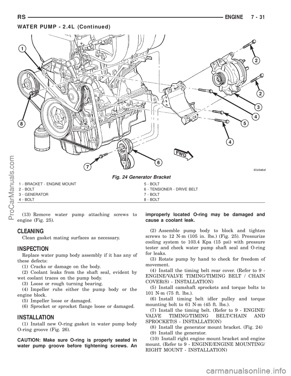
(13) Remove water pump attaching screws to
engine (Fig. 25).
CLEANING
Clean gasket mating surfaces as necessary.
INSPECTION
Replace water pump body assembly if it has any of
these defects:
(1) Cracks or damage on the body.
(2) Coolant leaks from the shaft seal, evident by
wet coolant traces on the pump body.
(3) Loose or rough turning bearing.
(4) Impeller rubs either the pump body or the
engine block.
(5) Impeller loose or damaged.
(6) Sprocket or sprocket flange loose or damaged.
INSTALLATION
(1) Install new O-ring gasket in water pump body
O-ring groove (Fig. 26).
CAUTION: Make sure O-ring is properly seated in
water pump groove before tightening screws. Animproperly located O-ring may be damaged and
cause a coolant leak.
(2) Assemble pump body to block and tighten
screws to 12 N´m (105 in. lbs.) (Fig. 25). Pressurize
cooling system to 103.4 Kpa (15 psi) with pressure
tester and check water pump shaft seal and O-ring
for leaks.
(3) Rotate pump by hand to check for freedom of
movement.
(4) Install the timing belt rear cover. (Refer to 9 -
ENGINE/VALVE TIMING/TIMING BELT / CHAIN
COVER(S) - INSTALLATION)
(5) Install camshaft sprockets and torque bolts to
101 N´m (75 ft. lbs.).
(6) Install timing belt idler pulley and torque
mounting bolt to 61 N´m (45 ft. lbs.).
(7) Install the timing belt. (Refer to 9 - ENGINE/
VALVE TIMING/TIMING BELT/CHAIN AND
SPROCKET(S - INSTALLATION)
(8) Install the generator mount bracket. (Fig. 24)
(9) Install the generator.
(10) Install right engine mount bracket and engine
mount. (Refer to 9 - ENGINE/ENGINE MOUNTING/
RIGHT MOUNT - INSTALLATION)
Fig. 24 Generator Bracket
1 - BRACKET - ENGINE MOUNT 5 - BOLT
2 - BOLT 6 - TENSIONER - DRIVE BELT
3 - GENERATOR 7 - BOLT
4 - BOLT 8 - BOLT
RSENGINE7-31
WATER PUMP - 2.4L (Continued)
ProCarManuals.com
Page 299 of 2321
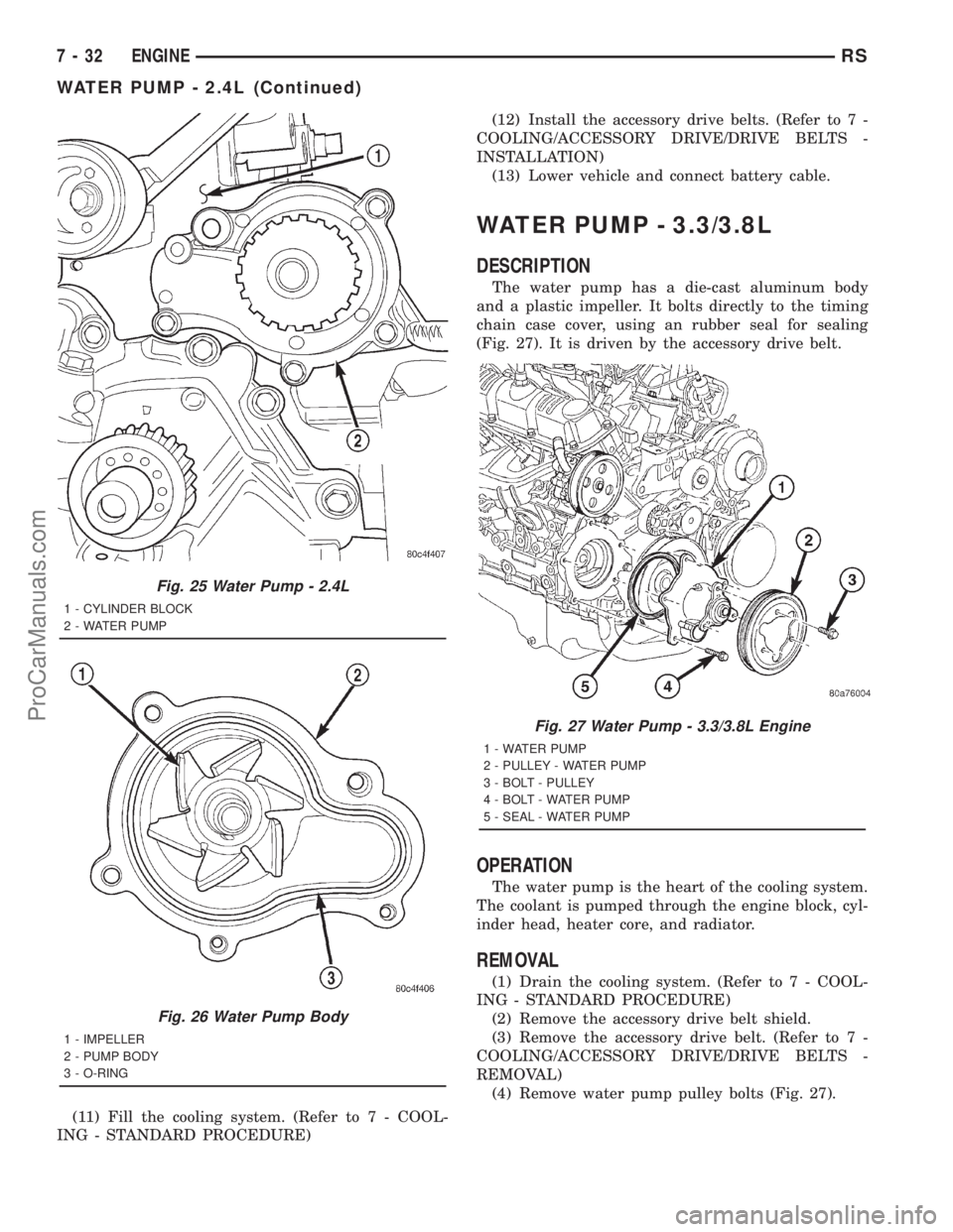
(11) Fill the cooling system. (Refer to 7 - COOL-
ING - STANDARD PROCEDURE)(12) Install the accessory drive belts. (Refer to 7 -
COOLING/ACCESSORY DRIVE/DRIVE BELTS -
INSTALLATION)
(13) Lower vehicle and connect battery cable.
WATER PUMP - 3.3/3.8L
DESCRIPTION
The water pump has a die-cast aluminum body
and a plastic impeller. It bolts directly to the timing
chain case cover, using an rubber seal for sealing
(Fig. 27). It is driven by the accessory drive belt.
OPERATION
The water pump is the heart of the cooling system.
The coolant is pumped through the engine block, cyl-
inder head, heater core, and radiator.
REMOVAL
(1) Drain the cooling system. (Refer to 7 - COOL-
ING - STANDARD PROCEDURE)
(2) Remove the accessory drive belt shield.
(3) Remove the accessory drive belt. (Refer to 7 -
COOLING/ACCESSORY DRIVE/DRIVE BELTS -
REMOVAL)
(4) Remove water pump pulley bolts (Fig. 27).
Fig. 25 Water Pump - 2.4L
1 - CYLINDER BLOCK
2 - WATER PUMP
Fig. 26 Water Pump Body
1 - IMPELLER
2 - PUMP BODY
3 - O-RING
Fig. 27 Water Pump - 3.3/3.8L Engine
1 - WATER PUMP
2 - PULLEY - WATER PUMP
3 - BOLT - PULLEY
4 - BOLT - WATER PUMP
5 - SEAL - WATER PUMP
7 - 32 ENGINERS
WATER PUMP - 2.4L (Continued)
ProCarManuals.com
Page 301 of 2321
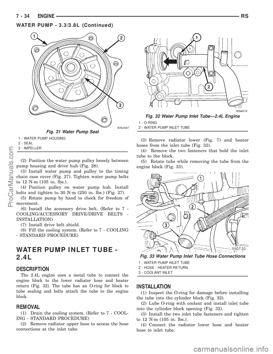
(2) Position the water pump pulley loosely between
pump housing and drive hub (Fig. 28).
(3) Install water pump and pulley to the timing
chain case cover (Fig. 27). Tighten water pump bolts
to 12 N´m (105 in. lbs.).
(4) Position pulley on water pump hub. Install
bolts and tighten to 30 N´m (250 in. lbs.) (Fig. 27).
(5) Rotate pump by hand to check for freedom of
movement.
(6) Install the accessory drive belt. (Refer to 7 -
COOLING/ACCESSORY DRIVE/DRIVE BELTS -
INSTALLATION)
(7) Install drive belt shield.
(8) Fill the cooling system. (Refer to 7 - COOLING
- STANDARD PROCEDURE)
WATER PUMP INLET TUBE -
2.4L
DESCRIPTION
The 2.4L engine uses a metal tube to connect the
engine block to the lower radiator hose and heater
return (Fig. 32). The tube has an O-ring for block to
tube sealing and bolts attach the tube to the engine
block.
REMOVAL
(1) Drain the cooling system. (Refer to 7 - COOL-
ING - STANDARD PROCEDURE)
(2) Remove radiator upper hose to access the hose
connections at the inlet tube.(3) Remove radiator lower (Fig. 7) and heater
hoses from the inlet tube (Fig. 33).
(4) Remove the two fasteners that hold the inlet
tube to the block.
(5) Rotate tube while removing the tube from the
engine block (Fig. 33).
INSTALLATION
(1) Inspect the O-ring for damage before installing
the tube into the cylinder block (Fig. 32).
(2) Lube O-ring with coolant and install inlet tube
into the cylinder block opening (Fig. 32).
(3) Install the two inlet tube fasteners and tighten
to 12 N´m (105 in. lbs.).
(4) Connect the radiator lower hose and heater
hose to inlet tube.
Fig. 31 Water Pump Seal
1 - WATER PUMP HOUSING
2 - SEAL
3 - IMPELLER
Fig. 32 Water Pump Inlet TubeÐ2.4L Engine
1 - O-RING
2 - WATER PUMP INLET TUBE
Fig. 33 Water Pump Inlet Tube Hose Connections
1 - WATER PUMP INLET TUBE
2 - HOSE - HEATER RETURN
3 - COOLANT INLET
7 - 34 ENGINERS
WATER PUMP - 3.3/3.8L (Continued)
ProCarManuals.com
Page 302 of 2321
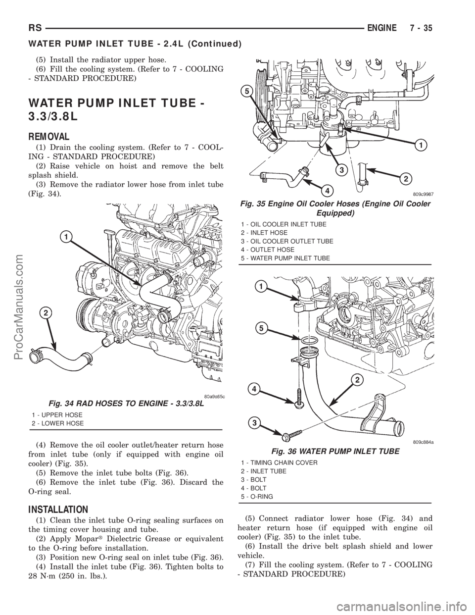
(5) Install the radiator upper hose.
(6) Fill the cooling system. (Refer to 7 - COOLING
- STANDARD PROCEDURE)
WATER PUMP INLET TUBE -
3.3/3.8L
REMOVAL
(1) Drain the cooling system. (Refer to 7 - COOL-
ING - STANDARD PROCEDURE)
(2) Raise vehicle on hoist and remove the belt
splash shield.
(3) Remove the radiator lower hose from inlet tube
(Fig. 34).
(4) Remove the oil cooler outlet/heater return hose
from inlet tube (only if equipped with engine oil
cooler) (Fig. 35).
(5) Remove the inlet tube bolts (Fig. 36).
(6) Remove the inlet tube (Fig. 36). Discard the
O-ring seal.
INSTALLATION
(1) Clean the inlet tube O-ring sealing surfaces on
the timing cover housing and tube.
(2) Apply MopartDielectric Grease or equivalent
to the O-ring before installation.
(3) Position new O-ring seal on inlet tube (Fig. 36).
(4) Install the inlet tube (Fig. 36). Tighten bolts to
28 N´m (250 in. lbs.).(5) Connect radiator lower hose (Fig. 34) and
heater return hose (if equipped with engine oil
cooler) (Fig. 35) to the inlet tube.
(6) Install the drive belt splash shield and lower
vehicle.
(7) Fill the cooling system. (Refer to 7 - COOLING
- STANDARD PROCEDURE)
Fig. 34 RAD HOSES TO ENGINE - 3.3/3.8L
1 - UPPER HOSE
2 - LOWER HOSE
Fig. 35 Engine Oil Cooler Hoses (Engine Oil Cooler
Equipped)
1 - OIL COOLER INLET TUBE
2 - INLET HOSE
3 - OIL COOLER OUTLET TUBE
4 - OUTLET HOSE
5 - WATER PUMP INLET TUBE
Fig. 36 WATER PUMP INLET TUBE
1 - TIMING CHAIN COVER
2 - INLET TUBE
3 - BOLT
4 - BOLT
5 - O-RING
RSENGINE7-35
WATER PUMP INLET TUBE - 2.4L (Continued)
ProCarManuals.com
Page 308 of 2321
COOLING 2.5L TURBO DIESEL
TABLE OF CONTENTS
page page
COOLING 2.5L TURBO DIESEL
DESCRIPTION............................1
DIAGNOSIS AND TESTING..................1
COOLING SYSTEM......................1
COOLING SYSTEM LEAK TEST.............6
COOLING SYSTEM FLOW CHECK..........7COOLING SYSTEM AERATION.............7
CLEANING...............................7
INSPECTION.............................7
SPECIFICATIONS.........................8
ACCESSORY DRIVE.......................9
ENGINE................................14
COOLING 2.5L TURBO DIESEL
DESCRIPTION - COOLING SYSTEM
The cooling system regulates engine operating tem-
perature. It allows the engine to reach normal oper-
ating temperature as quickly as possible, maintains
normal operating temperature and prevents over-
heating.
The cooling system also provides a means of heat-
ing the passenger compartment. The cooling system
is pressurized and uses a centrifugal water pump to
circulate coolant throughout the system. A separate
and remotely mounted, pressurized coolant tank
using a pressure/vent cap is used.
COOLING SYSTEM COMPONENTS
The cooling system consists of:
²Charge Air Cooler
²Electric Cooling Fans
²A aluminum-core radiator with plastic side
tanks
²A separate pressurized coolant tank
²A pressure/vent cap on the coolant tank
²Fan shroud
²Thermostat
²Coolant
²Low coolant warning lamp
²Coolant temperature gauge
²Water pump
²Hoses and hose clamps
DIAGNOSIS AND TESTING - COOLING SYSTEM
Establish what driving conditions caused the com-
plaint. Abnormal loads on the cooling system such as
the following may be the cause:
(1) PROLONGED IDLE, VERY HIGH AMBIENT
TEMPERATURE, SLIGHT TAIL WIND AT IDLE,
SLOW TRAFFIC, TRAFFIC JAMS, HIGH SPEED
OR STEEP GRADES.
Driving techniques that avoid overheating are:
²Idle with A/C off when temperature gauge is at
end of normal range.
²Increasing engine speed for more air flow is rec-
ommended.
(2) TRAILER TOWING:
Consult Trailer Towing section of owners manual.
Do not exceed limits.
(3) RECENT SERVICE OR ACCIDENT REPAIR:
Determine if any recent service has been per-
formed on vehicle that may effect cooling system.
This may be:
²Engine adjustments (incorrect timing)
²Slipping engine accessory drive belt
²Brakes (possibly dragging)
²Changed parts (incorrect water pump)
²Reconditioned radiator or cooling system refill-
ing (possibly under filled or air trapped in system).
NOTE: If investigation reveals none of the previous
items as a cause for an engine overheating com-
plaint, refer to following Cooling System Diagnosis
charts.
These charts are to be used as a quick-reference
only.
RGCOOLING 2.5L TURBO DIESEL7a-1
ProCarManuals.com
Page 329 of 2321
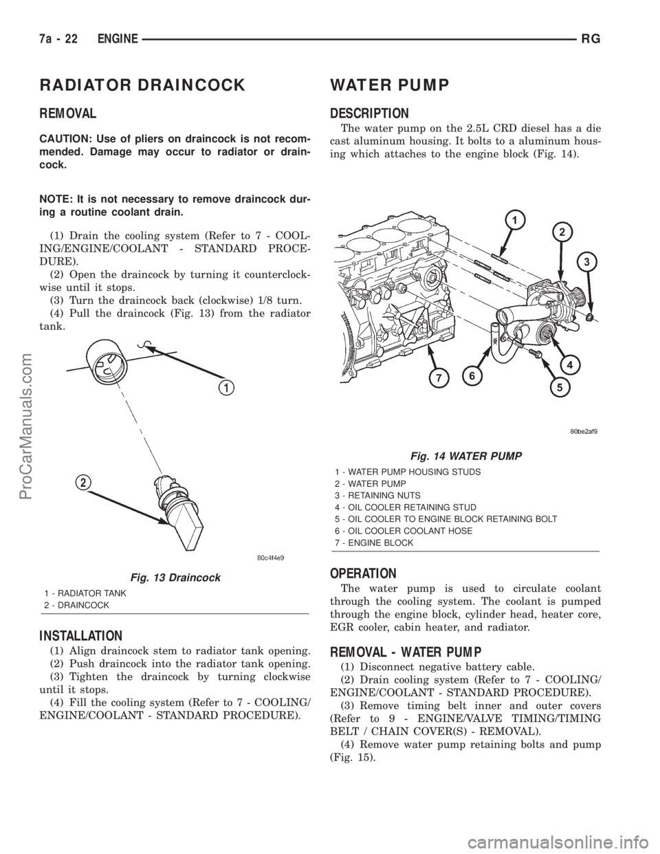
RADIATOR DRAINCOCK
REMOVAL
CAUTION: Use of pliers on draincock is not recom-
mended. Damage may occur to radiator or drain-
cock.
NOTE: It is not necessary to remove draincock dur-
ing a routine coolant drain.
(1) Drain the cooling system (Refer to 7 - COOL-
ING/ENGINE/COOLANT - STANDARD PROCE-
DURE).
(2) Open the draincock by turning it counterclock-
wise until it stops.
(3) Turn the draincock back (clockwise) 1/8 turn.
(4) Pull the draincock (Fig. 13) from the radiator
tank.
INSTALLATION
(1) Align draincock stem to radiator tank opening.
(2) Push draincock into the radiator tank opening.
(3) Tighten the draincock by turning clockwise
until it stops.
(4) Fill the cooling system (Refer to 7 - COOLING/
ENGINE/COOLANT - STANDARD PROCEDURE).
WATER PUMP
DESCRIPTION
The water pump on the 2.5L CRD diesel has a die
cast aluminum housing. It bolts to a aluminum hous-
ing which attaches to the engine block (Fig. 14).
OPERATION
The water pump is used to circulate coolant
through the cooling system. The coolant is pumped
through the engine block, cylinder head, heater core,
EGR cooler, cabin heater, and radiator.
REMOVAL - WATER PUMP
(1) Disconnect negative battery cable.
(2) Drain cooling system (Refer to 7 - COOLING/
ENGINE/COOLANT - STANDARD PROCEDURE).
(3) Remove timing belt inner and outer covers
(Refer to 9 - ENGINE/VALVE TIMING/TIMING
BELT / CHAIN COVER(S) - REMOVAL).
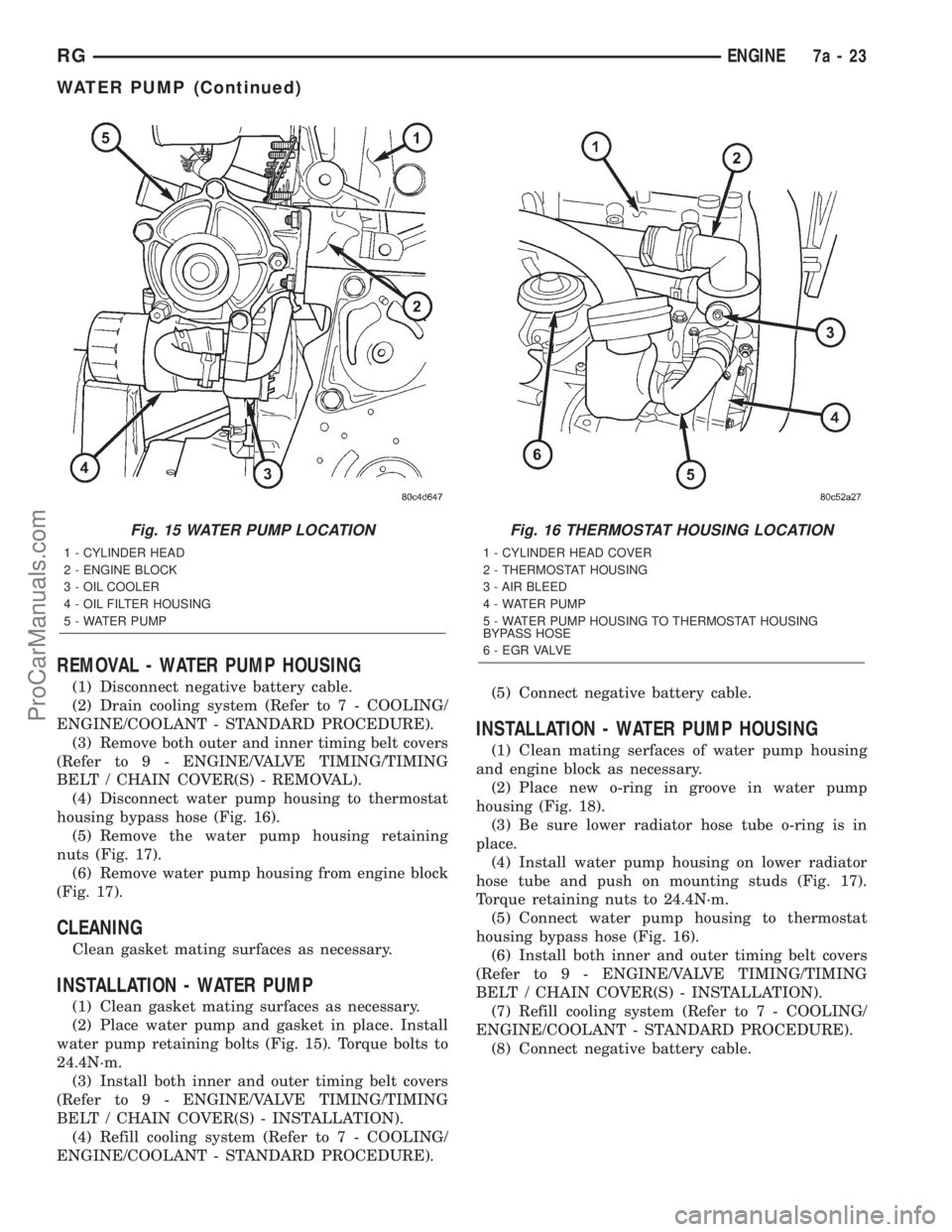
(4) Remove water pump retaining bolts and pump
(Fig. 15).
Fig. 13 Draincock
1 - RADIATOR TANK
2 - DRAINCOCK
Fig. 14 WATER PUMP
1 - WATER PUMP HOUSING STUDS
2 - WATER PUMP
3 - RETAINING NUTS
4 - OIL COOLER RETAINING STUD
5 - OIL COOLER TO ENGINE BLOCK RETAINING BOLT
6 - OIL COOLER COOLANT HOSE
7 - ENGINE BLOCK
7a - 22 ENGINERG
ProCarManuals.com
Page 330 of 2321
REMOVAL - WATER PUMP HOUSING
(1) Disconnect negative battery cable.
(2) Drain cooling system (Refer to 7 - COOLING/
ENGINE/COOLANT - STANDARD PROCEDURE).
(3) Remove both outer and inner timing belt covers
(Refer to 9 - ENGINE/VALVE TIMING/TIMING
BELT / CHAIN COVER(S) - REMOVAL).
(4) Disconnect water pump housing to thermostat
housing bypass hose (Fig. 16).
(5) Remove the water pump housing retaining
nuts (Fig. 17).
(6) Remove water pump housing from engine block
(Fig. 17).
CLEANING
Clean gasket mating surfaces as necessary.
INSTALLATION - WATER PUMP
(1) Clean gasket mating surfaces as necessary.
(2) Place water pump and gasket in place. Install
water pump retaining bolts (Fig. 15). Torque bolts to
24.4N´m.
(3) Install both inner and outer timing belt covers
(Refer to 9 - ENGINE/VALVE TIMING/TIMING
BELT / CHAIN COVER(S) - INSTALLATION).
(4) Refill cooling system (Refer to 7 - COOLING/
ENGINE/COOLANT - STANDARD PROCEDURE).(5) Connect negative battery cable.
INSTALLATION - WATER PUMP HOUSING
(1) Clean mating serfaces of water pump housing
and engine block as necessary.
(2) Place new o-ring in groove in water pump
housing (Fig. 18).
(3) Be sure lower radiator hose tube o-ring is in
place.
(4) Install water pump housing on lower radiator
hose tube and push on mounting studs (Fig. 17).
Torque retaining nuts to 24.4N´m.
(5) Connect water pump housing to thermostat
housing bypass hose (Fig. 16).
(6) Install both inner and outer timing belt covers
(Refer to 9 - ENGINE/VALVE TIMING/TIMING
BELT / CHAIN COVER(S) - INSTALLATION).
(7) Refill cooling system (Refer to 7 - COOLING/
ENGINE/COOLANT - STANDARD PROCEDURE).
(8) Connect negative battery cable.
Fig. 15 WATER PUMP LOCATION
1 - CYLINDER HEAD
2 - ENGINE BLOCK
3 - OIL COOLER
4 - OIL FILTER HOUSING
5 - WATER PUMP
Fig. 16 THERMOSTAT HOUSING LOCATION
1 - CYLINDER HEAD COVER
2 - THERMOSTAT HOUSING
3 - AIR BLEED
4 - WATER PUMP
5 - WATER PUMP HOUSING TO THERMOSTAT HOUSING
BYPASS HOSE
6 - E G R VA LV E
RGENGINE7a-23
WATER PUMP (Continued)
ProCarManuals.com