DODGE TOWN AND COUNTRY 2003 Service Manual
Manufacturer: DODGE, Model Year: 2003, Model line: TOWN AND COUNTRY, Model: DODGE TOWN AND COUNTRY 2003Pages: 2177, PDF Size: 59.81 MB
Page 1411 of 2177
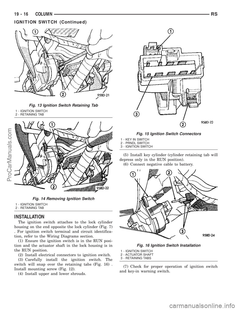
INSTALLATION
The ignition switch attaches to the lock cylinder
housing on the end opposite the lock cylinder (Fig. 7)
. For ignition switch terminal and circuit identifica-
tion, refer to the Wiring Diagrams section.
(1) Ensure the ignition switch is in the RUN posi-
tion and the actuator shaft in the lock housing is in
the RUN position.
(2) Install electrical connectors to ignition switch.
(3) Carefully install the ignition switch. The
switch will snap over the retaining tabs (Fig. 16) .
Install mounting screw (Fig. 12).
(4) Install upper and lower shrouds.(5) Install key cylinder (cylinder retaining tab will
depress only in the RUN position).
(6) Connect negative cable to battery.
(7) Check for proper operation of ignition switch
and key-in warning switch.
Fig. 13 Ignition Switch Retaining Tab
1 - IGNITION SWITCH
2 - RETAINING TAB
Fig. 14 Removing Ignition Switch
1 - IGNITION SWITCH
2 - RETAINING TAB
Fig. 15 Ignition Switch Connectors
1 - KEY IN SWITCH
2 - PRNDL SWITCH
3 - IGNITION SWITCH
Fig. 16 Ignition Switch Installation
1 - IGNITION SWITCH
2 - ACTUATOR SHAFT
3 - RETAINING TABS
19 - 16 COLUMNRS
IGNITION SWITCH (Continued)
ProCarManuals.com
Page 1412 of 2177
LOCK CYLINDER HOUSING
DESCRIPTION - IGNITION INTERLOCK
All vehicles equipped with automatic transaxles
have an interlock system. The system prevents shift-
ing the vehicle out of Park unless the ignition lock
cylinder is in the Unlock, Run or Start position. In
addition, the operator cannot rotate the key to the
lock position unless the shifter is in the park posi-
tion. On vehicles equipped with floor shift refer to
the - Transaxle for Automatic Transmission Shifter/
Ignition Interlock.
REMOVAL
NOTE: Before proceeding, review all Steering Col-
umn and Airbag Warnings and Cautions. (Refer to
19 - STEERING/COLUMN - WARNING)(Refer to 8 -
ELECTRICAL/RESTRAINTS - WARNING)
(1) Remove battery ground cable terminal from
battery negative post and isolate.
(2) Under instrument panel, remove silencer panel
below lower steering column cover.
(3) Remove screws securing lower steering column
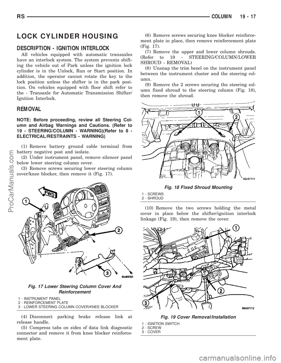
cover/knee blocker, then remove it (Fig. 17).
(4) Disconnect parking brake release link at
release handle.
(5) Compress tabs on sides of data link diagnostic
connector and remove it from knee blocker reinforce-
ment plate.(6) Remove screws securing knee blocker reinforce-
ment plate in place, then remove reinforcement plate
(Fig. 17).
(7) Remove the upper and lower column shrouds.
(Refer to 19 - STEERING/COLUMN/LOWER
SHROUD - REMOVAL)
(8) Unsnap the trim bezel on the instrument panel
between the instrument cluster and the steering col-
umn.
(9) Remove the 2 screws securing the steering col-
umn fixed shroud to the steering column (Fig. 18),
then remove the shroud.
(10) Remove the two screws holding the metal
cover in place below the shifter/ignition interlock
linkage (Fig. 19), then remove the cover.
Fig. 17 Lower Steering Column Cover And
Reinforcement
1 - INSTRUMENT PANEL
2 - REINFORCEMENT PLATE
3 - LOWER STEERING COLUMN COVER/KNEE BLOCKER
Fig. 18 Fixed Shroud Mounting
1 - SCREWS
2 - SHROUD
Fig. 19 Cover Removal/Installation
1 - IGNITION SWITCH
2 - SCREW
3 - COVER
RSCOLUMN19-17
ProCarManuals.com
Page 1413 of 2177
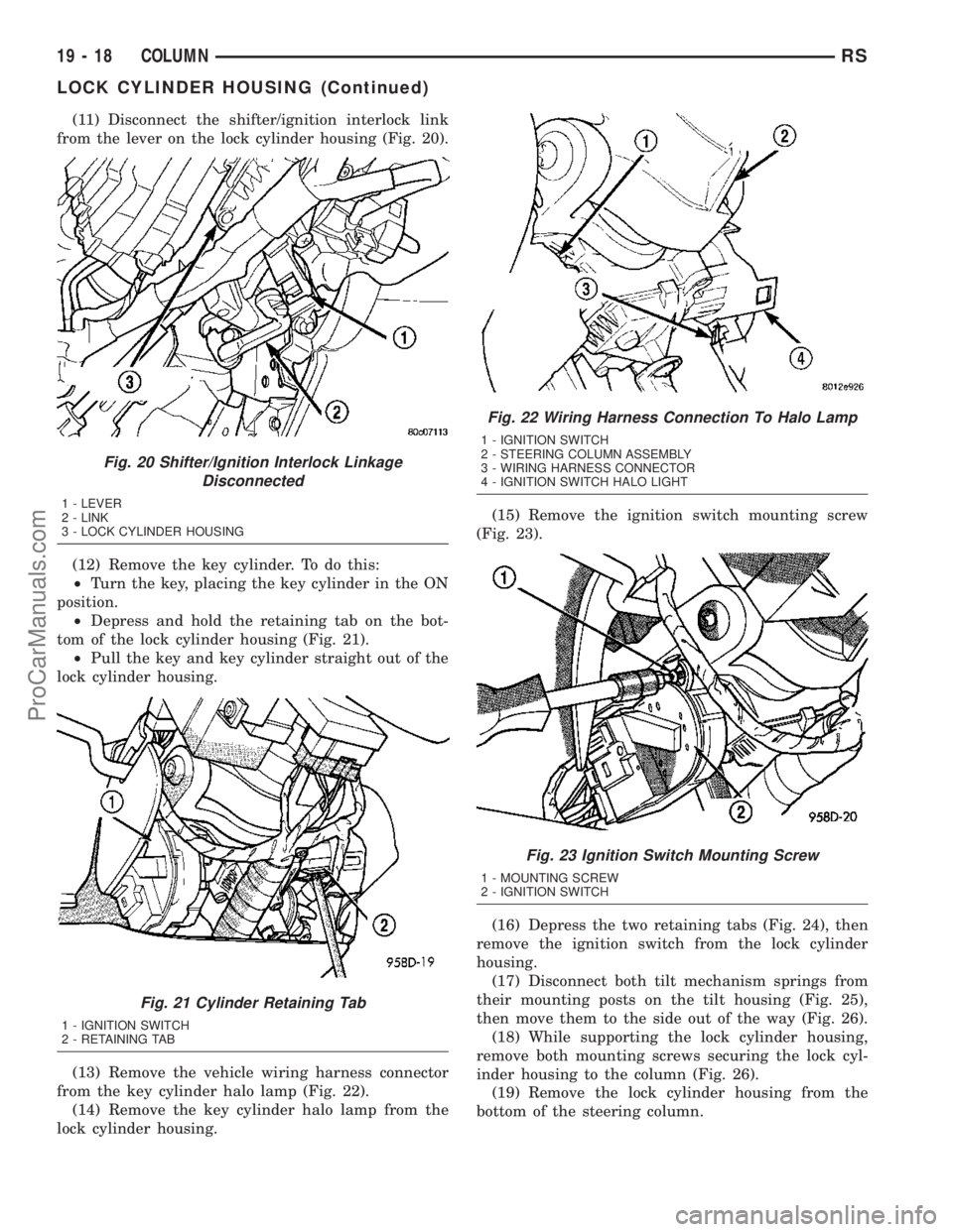
(11) Disconnect the shifter/ignition interlock link
from the lever on the lock cylinder housing (Fig. 20).
(12) Remove the key cylinder. To do this:
²Turn the key, placing the key cylinder in the ON
position.
²Depress and hold the retaining tab on the bot-
tom of the lock cylinder housing (Fig. 21).
²Pull the key and key cylinder straight out of the
lock cylinder housing.
(13) Remove the vehicle wiring harness connector
from the key cylinder halo lamp (Fig. 22).
(14) Remove the key cylinder halo lamp from the
lock cylinder housing.(15) Remove the ignition switch mounting screw
(Fig. 23).
(16) Depress the two retaining tabs (Fig. 24), then
remove the ignition switch from the lock cylinder
housing.
(17) Disconnect both tilt mechanism springs from
their mounting posts on the tilt housing (Fig. 25),
then move them to the side out of the way (Fig. 26).
(18) While supporting the lock cylinder housing,
remove both mounting screws securing the lock cyl-
inder housing to the column (Fig. 26).
(19) Remove the lock cylinder housing from the
bottom of the steering column.
Fig. 20 Shifter/Ignition Interlock Linkage
Disconnected
1 - LEVER
2 - LINK
3 - LOCK CYLINDER HOUSING
Fig. 21 Cylinder Retaining Tab
1 - IGNITION SWITCH
2 - RETAINING TAB
Fig. 22 Wiring Harness Connection To Halo Lamp
1 - IGNITION SWITCH
2 - STEERING COLUMN ASSEMBLY
3 - WIRING HARNESS CONNECTOR
4 - IGNITION SWITCH HALO LIGHT
Fig. 23 Ignition Switch Mounting Screw
1 - MOUNTING SCREW
2 - IGNITION SWITCH
19 - 18 COLUMNRS
LOCK CYLINDER HOUSING (Continued)
ProCarManuals.com
Page 1414 of 2177
INSTALLATION
(1) Install the lock cylinder housing in the bottom
of the steering column lining up the mounting holes.
(2) Install the self-tapping lock cylinder housing
mounting screws through the top of the column into
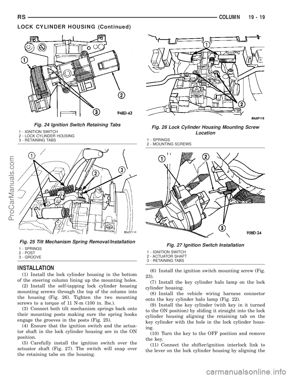
the housing (Fig. 26). Tighten the two mounting
screws to a torque of 11 N´m (100 in. lbs.).
(3) Connect both tilt mechanism springs back onto
their mounting posts making sure the spring hooks
engage the grooves in the posts (Fig. 25).
(4) Ensure that the ignition switch and the actua-
tor shaft in the lock cylinder housing are in the ON
position.
(5) Carefully install the ignition switch over the
actuator shaft (Fig. 27). The switch will snap over
the retaining tabs on the housing.(6) Install the ignition switch mounting screw (Fig.
23).
(7) Install the key cylinder halo lamp on the lock
cylinder housing.
(8) Install the vehicle wiring harness connector
onto the key cylinder halo lamp (Fig. 22).
(9) Install the key cylinder (with key in it turned
to the ON position) by sliding it straight into the lock
cylinder housing aligning the retaining tab on the
key cylinder with the hole in the lock cylinder hous-
ing.
(10) Turn the key to the OFF position and remove
the key.
(11) Connect the shifter/ignition interlock link to
the lever on the lock cylinder housing by aligning the
Fig. 24 Ignition Switch Retaining Tabs
1 - IGNITION SWITCH
2 - LOCK CYLINDER HOUSING
3 - RETAINING TABS
Fig. 25 Tilt Mechanism Spring Removal/Installation
1 - SPRINGS
2 - POST
3 - GROOVE
Fig. 26 Lock Cylinder Housing Mounting Screw
Location
1 - SPRINGS
2 - MOUNTING SCREWS
Fig. 27 Ignition Switch Installation
1 - IGNITION SWITCH
2 - ACTUATOR SHAFT
3 - RETAINING TABS
RSCOLUMN19-19
LOCK CYLINDER HOUSING (Continued)
ProCarManuals.com
Page 1415 of 2177
retaining tab on the lever with the ramp on the link
(Fig. 20), then pushing the two together.
(12) Install the metal cover in place below the
shifter/ignition interlock linkage using the two
screws (Fig. 19).
(13) Install the steering column fixed shroud on
the steering column (Fig. 18) using its 2 mounting
screws.
(14) Install the trim bezel on the instrument panel
above the steering column. The trim bezel is
mounted to the instrument panel using 2 screws (one
on each side of the column) and retaining clips.
(15) Install the lower and upper steering column
shrouds. (Refer to 19 - STEERING/COLUMN/
LOWER SHROUD - INSTALLATION)
(16) Install the knee blocker reinforcement plate
(Fig. 17).
(17) Connect the parking brake release link to the
release handle.
(18) Install the data link diagnostic connector to
the mounting hole in the reinforcement plate.
(19) Install the lower steering column cover/knee
blocker (Fig. 17).
(20) Connect the negative (ground) cable to the
battery terminal.
KEY/LOCK CYLINDER
DESCRIPTION
The lock cylinder is inserted in the end of the
housing opposite the ignition switch.
OPERATION
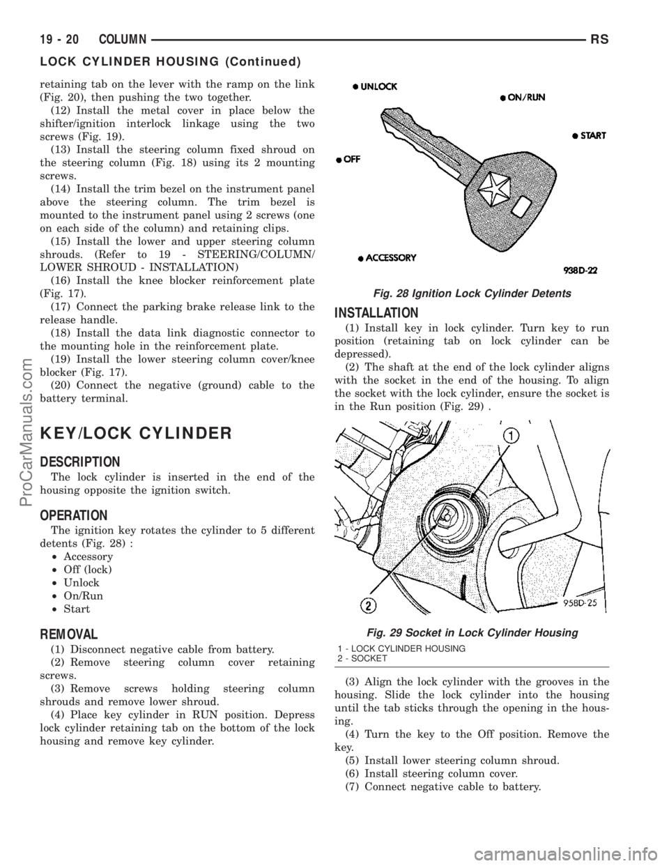
The ignition key rotates the cylinder to 5 different
detents (Fig. 28) :
²Accessory
²Off (lock)
²Unlock
²On/Run
²Start
REMOVAL
(1) Disconnect negative cable from battery.
(2) Remove steering column cover retaining
screws.
(3) Remove screws holding steering column
shrouds and remove lower shroud.
(4) Place key cylinder in RUN position. Depress
lock cylinder retaining tab on the bottom of the lock
housing and remove key cylinder.
INSTALLATION
(1) Install key in lock cylinder. Turn key to run
position (retaining tab on lock cylinder can be
depressed).
(2) The shaft at the end of the lock cylinder aligns
with the socket in the end of the housing. To align
the socket with the lock cylinder, ensure the socket is
in the Run position (Fig. 29) .
(3) Align the lock cylinder with the grooves in the
housing. Slide the lock cylinder into the housing
until the tab sticks through the opening in the hous-
ing.
(4) Turn the key to the Off position. Remove the
key.
(5) Install lower steering column shroud.
(6) Install steering column cover.
(7) Connect negative cable to battery.
Fig. 28 Ignition Lock Cylinder Detents
Fig. 29 Socket in Lock Cylinder Housing
1 - LOCK CYLINDER HOUSING
2 - SOCKET
19 - 20 COLUMNRS
LOCK CYLINDER HOUSING (Continued)
ProCarManuals.com
Page 1416 of 2177
GEAR SHIFT LEVER
REMOVAL
(1) Remove the knee blocker (Refer to 23 - BODY/
INSTRUMENT PANEL/STEERING COLUMN
OPENING COVER - REMOVAL).
(2) Remove the knee blocker reinforcement (Refer
to 23 - BODY/INSTRUMENT PANEL/KNEE
BLOCKER - REMOVAL).
(3) Remove the upper and lower shrouds (Refer to
19 - STEERING/COLUMN/LOWER SHROUD -
REMOVAL).
(4) Remove the cluster trim bezel (Refer to 23 -
BODY/INSTRUMENT PANEL/CLUSTER BEZEL -
REMOVAL).
(5) Remove the fixed shroud from the column.
(6) Disconnect the electrical connector to the BTSI.
(7) Remove the two screws securing the BTSI to
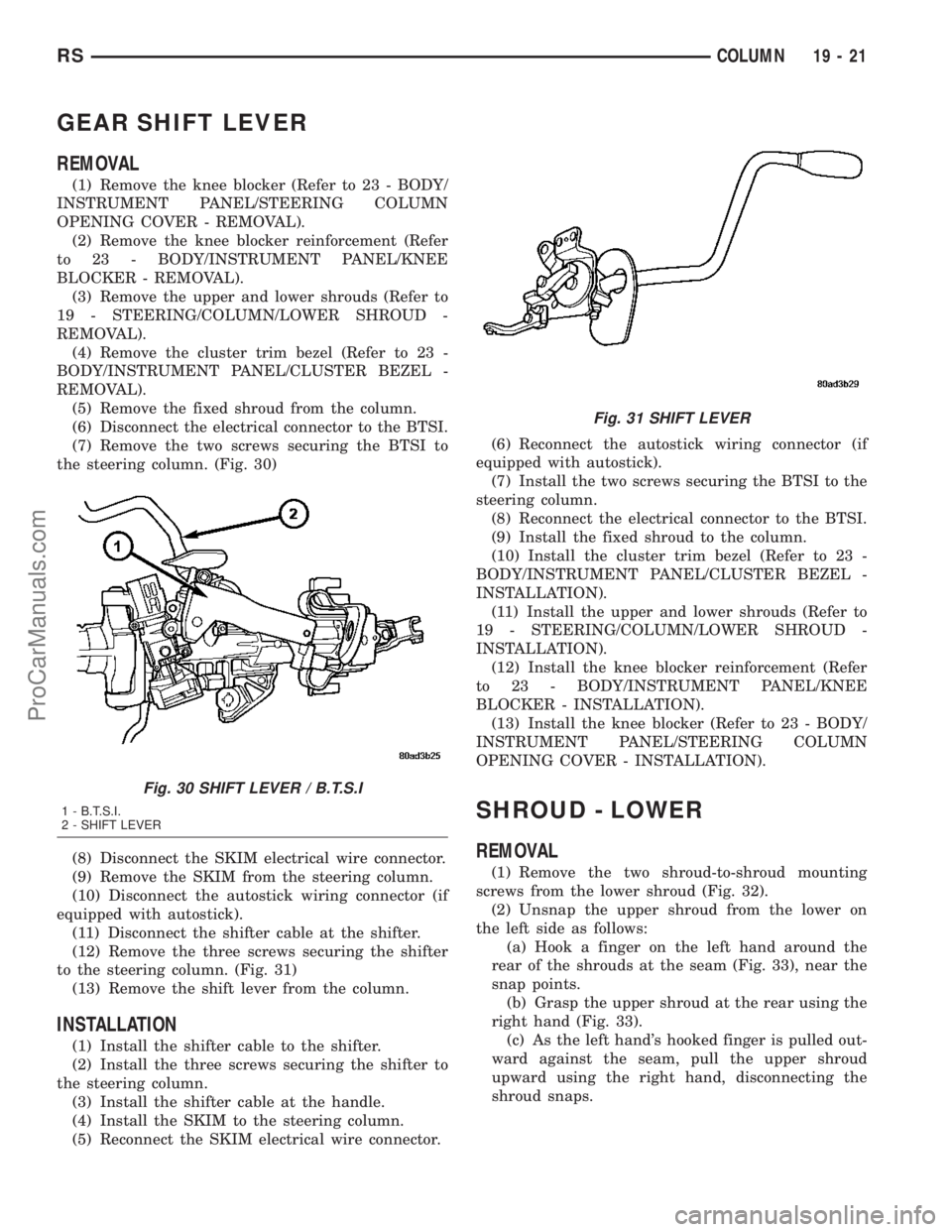
the steering column. (Fig. 30)
(8) Disconnect the SKIM electrical wire connector.
(9) Remove the SKIM from the steering column.
(10) Disconnect the autostick wiring connector (if
equipped with autostick).
(11) Disconnect the shifter cable at the shifter.
(12) Remove the three screws securing the shifter
to the steering column. (Fig. 31)
(13) Remove the shift lever from the column.
INSTALLATION
(1) Install the shifter cable to the shifter.
(2) Install the three screws securing the shifter to
the steering column.
(3) Install the shifter cable at the handle.
(4) Install the SKIM to the steering column.
(5) Reconnect the SKIM electrical wire connector.(6) Reconnect the autostick wiring connector (if
equipped with autostick).
(7) Install the two screws securing the BTSI to the
steering column.
(8) Reconnect the electrical connector to the BTSI.
(9) Install the fixed shroud to the column.
(10) Install the cluster trim bezel (Refer to 23 -
BODY/INSTRUMENT PANEL/CLUSTER BEZEL -
INSTALLATION).
(11) Install the upper and lower shrouds (Refer to
19 - STEERING/COLUMN/LOWER SHROUD -
INSTALLATION).
(12) Install the knee blocker reinforcement (Refer
to 23 - BODY/INSTRUMENT PANEL/KNEE
BLOCKER - INSTALLATION).
(13) Install the knee blocker (Refer to 23 - BODY/
INSTRUMENT PANEL/STEERING COLUMN
OPENING COVER - INSTALLATION).
SHROUD - LOWER
REMOVAL
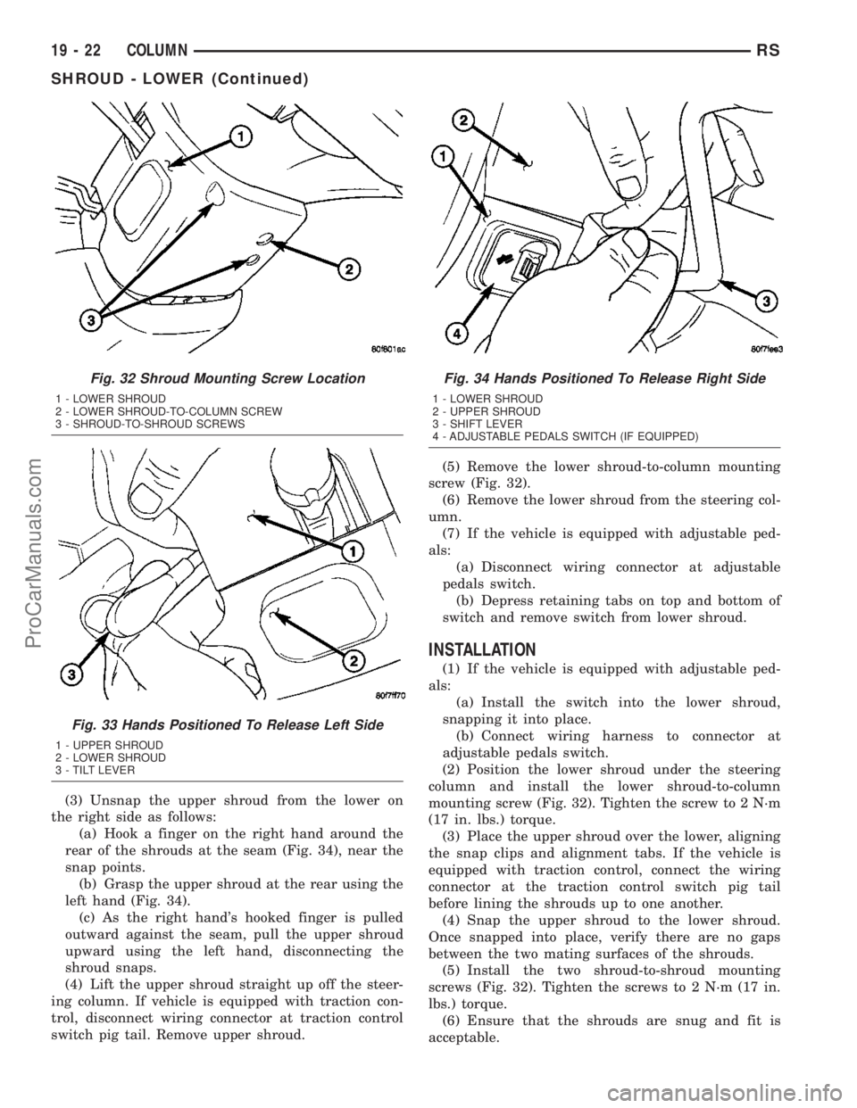
(1) Remove the two shroud-to-shroud mounting
screws from the lower shroud (Fig. 32).
(2) Unsnap the upper shroud from the lower on
the left side as follows:
(a) Hook a finger on the left hand around the
rear of the shrouds at the seam (Fig. 33), near the
snap points.
(b) Grasp the upper shroud at the rear using the
right hand (Fig. 33).
(c) As the left hand's hooked finger is pulled out-
ward against the seam, pull the upper shroud
upward using the right hand, disconnecting the
shroud snaps.
Fig. 30 SHIFT LEVER / B.T.S.I
1 - B.T.S.I.
2 - SHIFT LEVER
Fig. 31 SHIFT LEVER
RSCOLUMN19-21
ProCarManuals.com
Page 1417 of 2177
(3) Unsnap the upper shroud from the lower on
the right side as follows:
(a) Hook a finger on the right hand around the
rear of the shrouds at the seam (Fig. 34), near the
snap points.
(b) Grasp the upper shroud at the rear using the
left hand (Fig. 34).
(c) As the right hand's hooked finger is pulled
outward against the seam, pull the upper shroud
upward using the left hand, disconnecting the
shroud snaps.
(4) Lift the upper shroud straight up off the steer-
ing column. If vehicle is equipped with traction con-
trol, disconnect wiring connector at traction control
switch pig tail. Remove upper shroud.(5) Remove the lower shroud-to-column mounting
screw (Fig. 32).
(6) Remove the lower shroud from the steering col-
umn.
(7) If the vehicle is equipped with adjustable ped-
als:
(a) Disconnect wiring connector at adjustable
pedals switch.
(b) Depress retaining tabs on top and bottom of
switch and remove switch from lower shroud.
INSTALLATION
(1) If the vehicle is equipped with adjustable ped-
als:
(a) Install the switch into the lower shroud,
snapping it into place.
(b) Connect wiring harness to connector at
adjustable pedals switch.
(2) Position the lower shroud under the steering
column and install the lower shroud-to-column
mounting screw (Fig. 32). Tighten the screw to 2 N´m
(17 in. lbs.) torque.
(3) Place the upper shroud over the lower, aligning
the snap clips and alignment tabs. If the vehicle is
equipped with traction control, connect the wiring
connector at the traction control switch pig tail
before lining the shrouds up to one another.
(4) Snap the upper shroud to the lower shroud.
Once snapped into place, verify there are no gaps
between the two mating surfaces of the shrouds.
(5) Install the two shroud-to-shroud mounting
screws (Fig. 32). Tighten the screws to 2 N´m (17 in.
lbs.) torque.
(6) Ensure that the shrouds are snug and fit is
acceptable.
Fig. 32 Shroud Mounting Screw Location
1 - LOWER SHROUD
2 - LOWER SHROUD-TO-COLUMN SCREW
3 - SHROUD-TO-SHROUD SCREWS
Fig. 33 Hands Positioned To Release Left Side
1 - UPPER SHROUD
2 - LOWER SHROUD
3 - TILT LEVER
Fig. 34 Hands Positioned To Release Right Side
1 - LOWER SHROUD
2 - UPPER SHROUD
3 - SHIFT LEVER
4 - ADJUSTABLE PEDALS SWITCH (IF EQUIPPED)
19 - 22 COLUMNRS
SHROUD - LOWER (Continued)
ProCarManuals.com
Page 1418 of 2177
SHROUD - UPPER
REMOVAL
(1) Remove the two shroud-to-shroud mounting
screws from the lower shroud (Fig. 32).
(2) Unsnap the upper shroud from the lower on
the left side as follows:
(a) Hook a finger on the left hand around the
rear of the shrouds at the seam (Fig. 33), near the
snap points.
(b) Grasp the upper shroud at the rear using the
right hand (Fig. 33).
(c) As the left hand's hooked finger is pulled out-
ward against the seam, pull the upper shroud
upward using the right hand, disconnecting the
shroud snaps.
(3) Unsnap the upper shroud from the lower on
the right side as follows:
(a) Hook a finger on the right hand around the
rear of the shrouds at the seam (Fig. 34), near the
snap points.
(b) Grasp the upper shroud at the rear using the
left hand (Fig. 34).
(c) As the right hand's hooked finger is pulled
outward against the seam, pull the upper shroud
upward using the left hand, disconnecting the
shroud snaps.
(4) Lift the upper shroud straight up off the steer-
ing column. If vehicle is equipped with traction con-
trol, disconnect wiring connector at traction control
switch pig tail. If vehicle is equipped with power fold-
away mirrors (Export), disconnect wiring connector
at mirror switch pig tail. Remove upper shroud.
(5) If vehicle is equipped with traction control,
remove traction control switch from shroud.
(6) If vehicle is equipped with power foldaway mir-
rors (Export), remove power fold-away switch from
upper shroud.
INSTALLATION
(1) If the vehicle is equipped with power foldaway
mirrors (Export), install the power fold-away switch
in the upper shroud.
(2) If vehicle is equipped with traction control,
install the traction control switch in the upper
shroud.
(3) Place the upper shroud over the lower shroud,
aligning the snap clips and alignment tabs. If the
vehicle is equipped with traction control, connect the
wiring connector at the traction control switch pig
tail before lining the shrouds up to one another.
(4) Snap the upper shroud to the lower shroud.
Once snapped into place, verify there are no gaps
between the two mating surfaces of the shrouds.(5) Install the two shroud-to-shroud mounting
screws (Fig. 32). Tighten the screws to 2 N´m (17 in.
lbs.) torque.
(6) Ensure that the shrouds are snug and fit is
acceptable.
STEERING WHEEL
REMOVAL
NOTE: Before proceeding, (Refer to 19 - STEERING/
COLUMN - WARNING)(Refer to 8 - ELECTRICAL/RE-
STRAINTS - WARNING).
(1) Adjust the steering wheel so that the tires are
in thestraight-aheadposition.
(2) Disconnect and isolate the battery negative
cable.
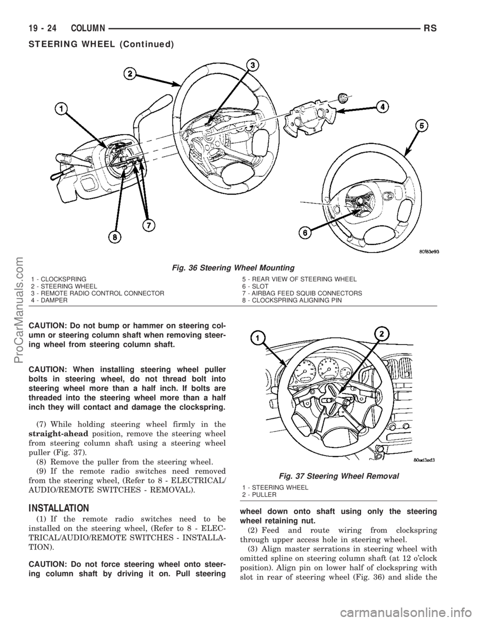
(3) Remove the two bolts from the rear of the
steering wheel attaching the driver airbag. Lift the
airbag from the steering wheel.
(4) Disconnect airbag squib wiring connectors from
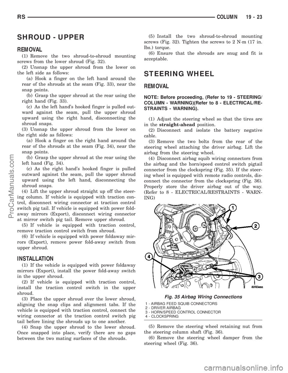
the airbag and the horn/speed control switch pigtail
connector from the clockspring (Fig. 35). If the steer-
ing wheel is equipped with remote radio controls, dis-
connect the connector from the clockspring (Fig. 36).
Properly store the driver airbag out of the way.
(Refer to 8 - ELECTRICAL/RESTRAINTS - WARN-
ING)
(5) Remove the steering wheel retaining nut from
the steering column shaft (Fig. 36).
(6) Remove the steering wheel damper from the
steering wheel (Fig. 36).
Fig. 35 Airbag Wiring Connections
1 - AIRBAG FEED SQUIB CONNECTORS
2 - DRIVER AIRBAG
3 - HORN/SPEED CONTROL CONNECTOR
4 - CLOCKSPRING
RSCOLUMN19-23
ProCarManuals.com
Page 1419 of 2177
CAUTION: Do not bump or hammer on steering col-
umn or steering column shaft when removing steer-
ing wheel from steering column shaft.
CAUTION: When installing steering wheel puller
bolts in steering wheel, do not thread bolt into
steering wheel more than a half inch. If bolts are
threaded into the steering wheel more than a half
inch they will contact and damage the clockspring.
(7) While holding steering wheel firmly in the
straight-aheadposition, remove the steering wheel
from steering column shaft using a steering wheel
puller (Fig. 37).
(8) Remove the puller from the steering wheel.
(9) If the remote radio switches need removed
from the steering wheel, (Refer to 8 - ELECTRICAL/
AUDIO/REMOTE SWITCHES - REMOVAL).
INSTALLATION
(1) If the remote radio switches need to be
installed on the steering wheel, (Refer to 8 - ELEC-
TRICAL/AUDIO/REMOTE SWITCHES - INSTALLA-
TION).
CAUTION: Do not force steering wheel onto steer-
ing column shaft by driving it on. Pull steeringwheel down onto shaft using only the steering
wheel retaining nut.
(2) Feed and route wiring from clockspring
through upper access hole in steering wheel.
(3) Align master serrations in steering wheel with
omitted spline on steering column shaft (at 12 o'clock
position). Align pin on lower half of clockspring with
slot in rear of steering wheel (Fig. 36) and slide the
Fig. 36 Steering Wheel Mounting
1 - CLOCKSPRING
2 - STEERING WHEEL
3 - REMOTE RADIO CONTROL CONNECTOR
4 - DAMPER5 - REAR VIEW OF STEERING WHEEL
6 - SLOT
7 - AIRBAG FEED SQUIB CONNECTORS
8 - CLOCKSPRING ALIGNING PIN
Fig. 37 Steering Wheel Removal
1 - STEERING WHEEL
2 - PULLER
19 - 24 COLUMNRS
STEERING WHEEL (Continued)
ProCarManuals.com
Page 1420 of 2177
steering wheel onto the steering column shaft by
hand. Use care not to pinch any wiring.
NOTE: Before installing the damper on the steering
wheel, inspect the damper to ensure the rubber iso-
lator on the damper is not deteriorated or damaged.
If the damper is installed with a damaged isolator, a
buzz, squeak or rattle condition may develop.
(4) Install the steering wheel damper on the steer-
ing wheel (Fig. 36).
(5) Install the steering wheel retaining nut.
Tighten the steering wheel retaining nut to 61 N´m
(45 ft. lbs.) torque.(6) If the steering wheel is equipped with remote
radio controls, connect the wiring connector to the
clockspring (Fig. 36).
(7) Connect the airbag squib wiring connectors to
the airbag and the horn/speed control switch pigtail
connector to the clockspring (Fig. 35).
(8) Install the driver airbag in the steering wheel.
Install and tighten the airbag attaching bolts to 10
N´m (90 in. lbs.) torque.
(9) To properly connect the battery and test the
airbag system, (Refer to 8 - ELECTRICAL/RE-
STRAINTS - DIAGNOSIS AND TESTING).
RSCOLUMN19-25
STEERING WHEEL (Continued)
ProCarManuals.com