DODGE TOWN AND COUNTRY 2003 Service Manual
TOWN AND COUNTRY 2003
DODGE
DODGE
https://www.carmanualsonline.info/img/12/56918/w960_56918-0.png
DODGE TOWN AND COUNTRY 2003 Service Manual
Trending: fuse box location, buttons, wheelbase, spark plugs, fuel tank capacity, fuel consumption, oil dipstick
Page 1701 of 2177
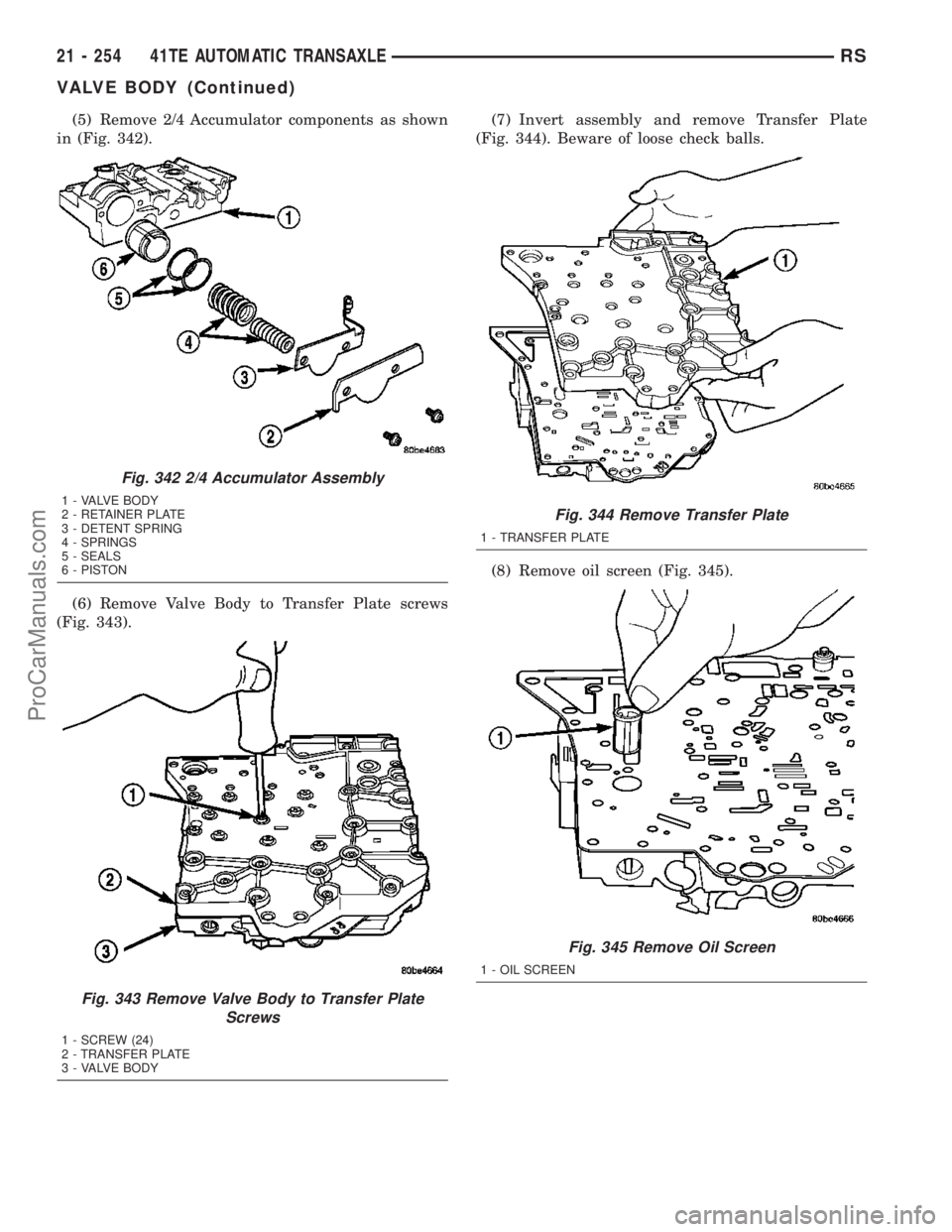
(5) Remove 2/4 Accumulator components as shown
in (Fig. 342).
(6) Remove Valve Body to Transfer Plate screws
(Fig. 343).(7) Invert assembly and remove Transfer Plate
(Fig. 344). Beware of loose check balls.
(8) Remove oil screen (Fig. 345).
Fig. 342 2/4 Accumulator Assembly
1 - VALVE BODY
2 - RETAINER PLATE
3 - DETENT SPRING
4 - SPRINGS
5 - SEALS
6 - PISTON
Fig. 343 Remove Valve Body to Transfer Plate
Screws
1 - SCREW (24)
2 - TRANSFER PLATE
3 - VALVE BODY
Fig. 344 Remove Transfer Plate
1 - TRANSFER PLATE
Fig. 345 Remove Oil Screen
1 - OIL SCREEN
21 - 254 41TE AUTOMATIC TRANSAXLERS
VALVE BODY (Continued)
ProCarManuals.com
Page 1702 of 2177
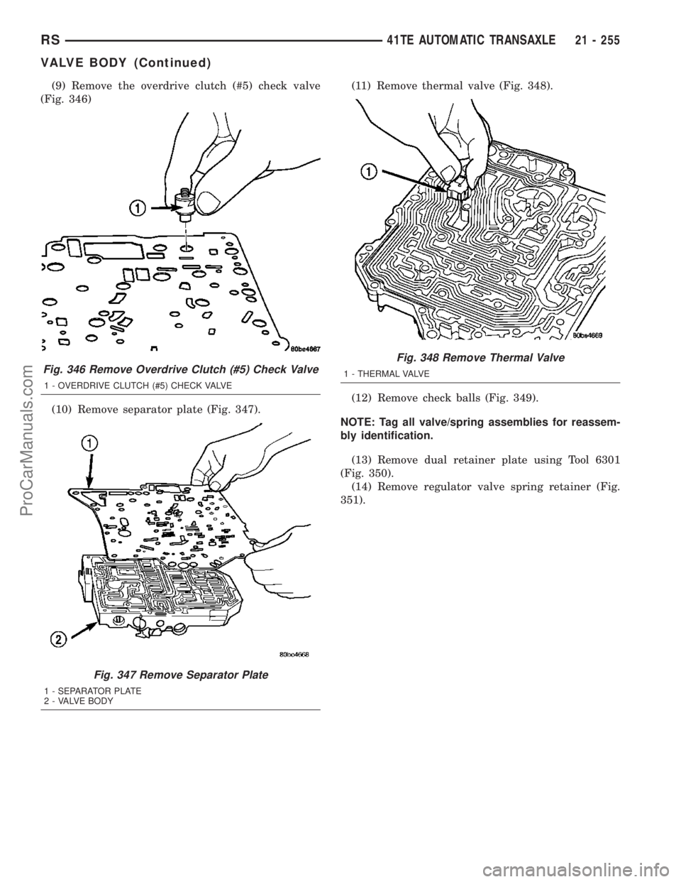
(9) Remove the overdrive clutch (#5) check valve
(Fig. 346)
(10) Remove separator plate (Fig. 347).(11) Remove thermal valve (Fig. 348).
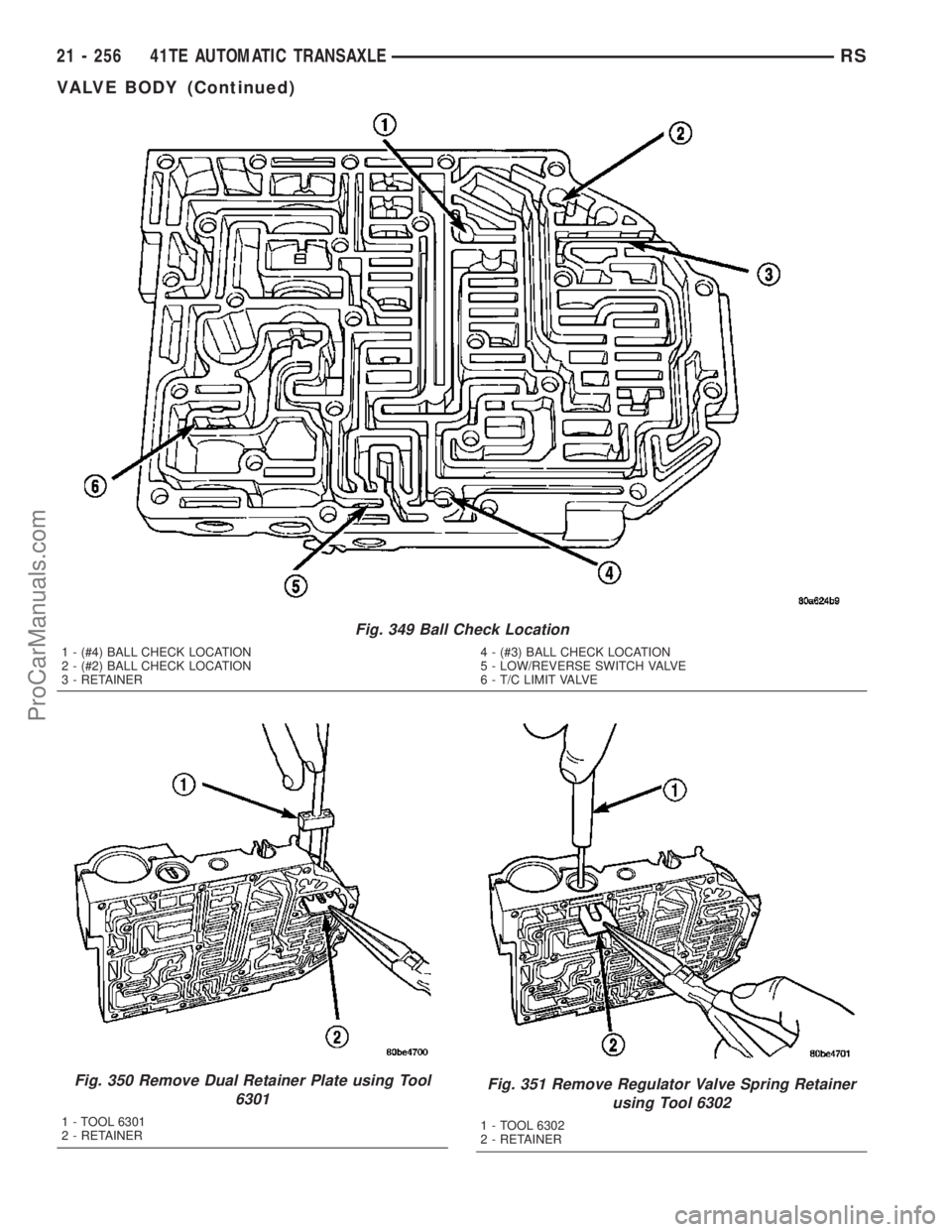
(12) Remove check balls (Fig. 349).
NOTE: Tag all valve/spring assemblies for reassem-
bly identification.
(13) Remove dual retainer plate using Tool 6301
(Fig. 350).
(14) Remove regulator valve spring retainer (Fig.
351).
Fig. 346 Remove Overdrive Clutch (#5) Check Valve
1 - OVERDRIVE CLUTCH (#5) CHECK VALVE
Fig. 347 Remove Separator Plate
1 - SEPARATOR PLATE
2 - VALVE BODY
Fig. 348 Remove Thermal Valve
1 - THERMAL VALVE
RS41TE AUTOMATIC TRANSAXLE21 - 255
VALVE BODY (Continued)
ProCarManuals.com
Page 1703 of 2177
Fig. 349 Ball Check Location
1 - (#4) BALL CHECK LOCATION
2 - (#2) BALL CHECK LOCATION
3 - RETAINER4 - (#3) BALL CHECK LOCATION
5 - LOW/REVERSE SWITCH VALVE
6 - T/C LIMIT VALVE
Fig. 350 Remove Dual Retainer Plate using Tool
6301
1 - TOOL 6301
2 - RETAINER
Fig. 351 Remove Regulator Valve Spring Retainer
using Tool 6302
1 - TOOL 6302
2 - RETAINER
21 - 256 41TE AUTOMATIC TRANSAXLERS
VALVE BODY (Continued)
ProCarManuals.com
Page 1704 of 2177
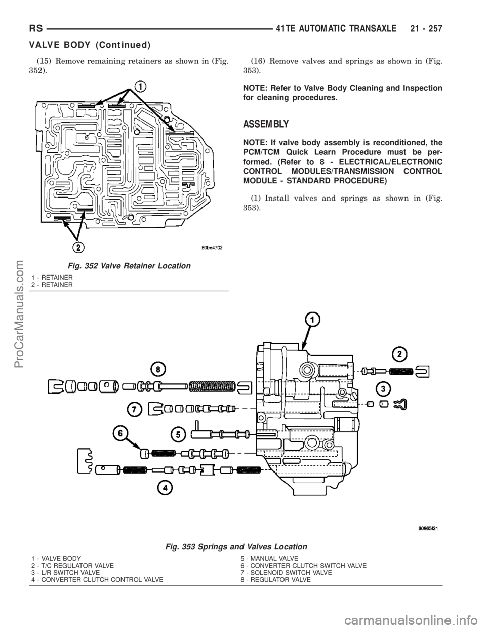
(15) Remove remaining retainers as shown in (Fig.
352).(16) Remove valves and springs as shown in (Fig.
353).
NOTE: Refer to Valve Body Cleaning and Inspection
for cleaning procedures.
ASSEMBLY
NOTE: If valve body assembly is reconditioned, the
PCM/TCM Quick Learn Procedure must be per-
formed. (Refer to 8 - ELECTRICAL/ELECTRONIC
CONTROL MODULES/TRANSMISSION CONTROL
MODULE - STANDARD PROCEDURE)
(1) Install valves and springs as shown in (Fig.
353).
Fig. 353 Springs and Valves Location
1 - VALVE BODY 5 - MANUAL VALVE
2 - T/C REGULATOR VALVE 6 - CONVERTER CLUTCH SWITCH VALVE
3 - L/R SWITCH VALVE 7 - SOLENOID SWITCH VALVE
4 - CONVERTER CLUTCH CONTROL VALVE 8 - REGULATOR VALVE
Fig. 352 Valve Retainer Location
1 - RETAINER
2 - RETAINER
RS41TE AUTOMATIC TRANSAXLE21 - 257
VALVE BODY (Continued)
ProCarManuals.com
Page 1705 of 2177
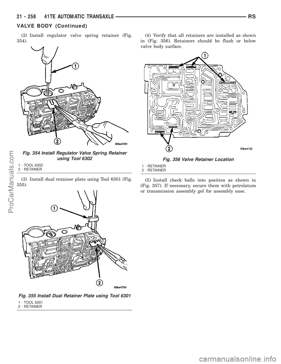
(2) Install regulator valve spring retainer (Fig.
354).
(3) Install dual retainer plate using Tool 6301 (Fig.
355).(4) Verify that all retainers are installed as shown
in (Fig. 356). Retainers should be flush or below
valve body surface.
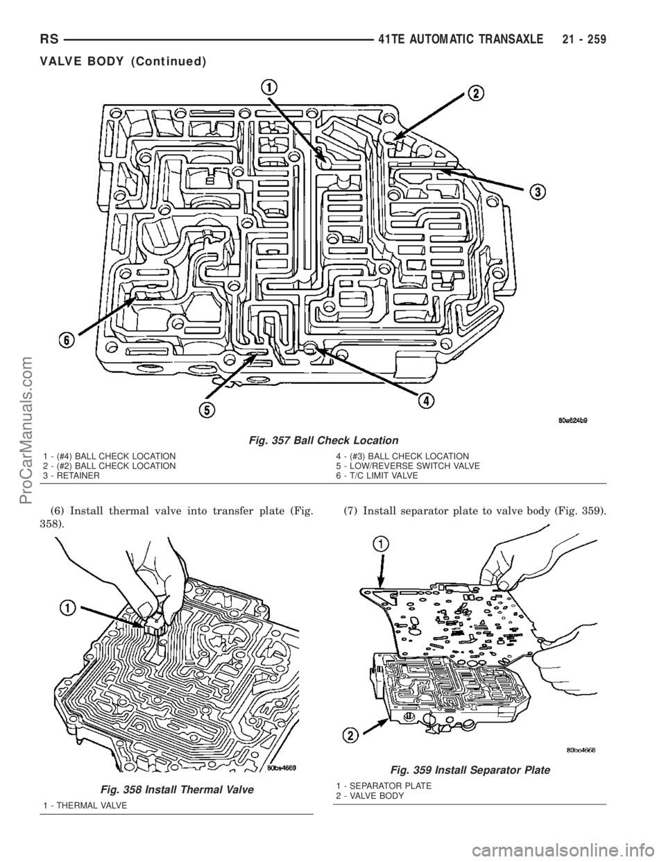
(5) Install check balls into position as shown in
(Fig. 357). If necessary, secure them with petrolatum
or transmission assembly gel for assembly ease.
Fig. 354 Install Regulator Valve Spring Retainer
using Tool 6302
1 - TOOL 6302
2 - RETAINER
Fig. 355 Install Dual Retainer Plate using Tool 6301
1 - TOOL 6301
2 - RETAINER
Fig. 356 Valve Retainer Location
1 - RETAINER
2 - RETAINER
21 - 258 41TE AUTOMATIC TRANSAXLERS
VALVE BODY (Continued)
ProCarManuals.com
Page 1706 of 2177
(6) Install thermal valve into transfer plate (Fig.
358).(7) Install separator plate to valve body (Fig. 359).
Fig. 357 Ball Check Location
1 - (#4) BALL CHECK LOCATION
2 - (#2) BALL CHECK LOCATION
3 - RETAINER4 - (#3) BALL CHECK LOCATION
5 - LOW/REVERSE SWITCH VALVE
6 - T/C LIMIT VALVE
Fig. 358 Install Thermal Valve
1 - THERMAL VALVE
Fig. 359 Install Separator Plate
1 - SEPARATOR PLATE
2 - VALVE BODY
RS41TE AUTOMATIC TRANSAXLE21 - 259
VALVE BODY (Continued)
ProCarManuals.com
Page 1707 of 2177
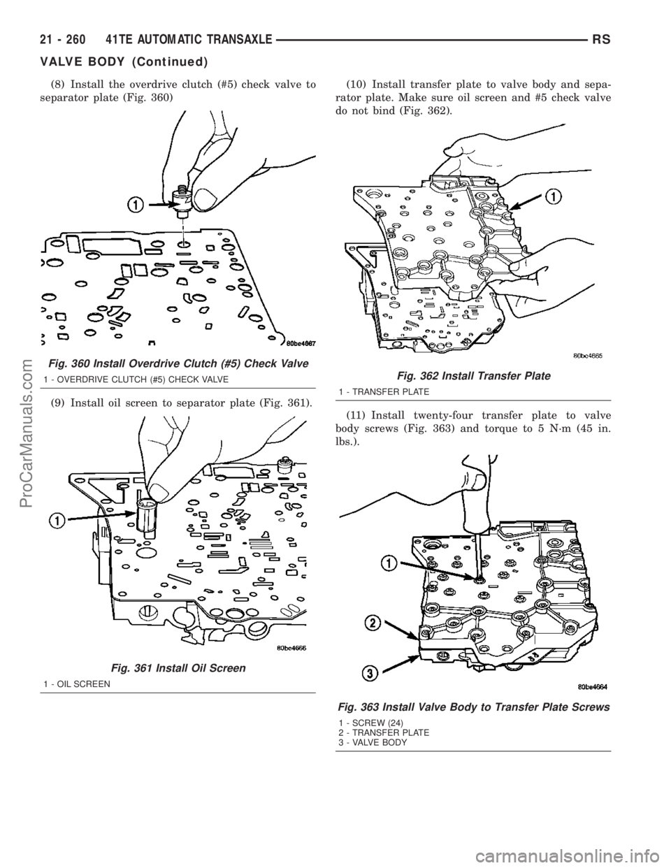
(8) Install the overdrive clutch (#5) check valve to
separator plate (Fig. 360)
(9) Install oil screen to separator plate (Fig. 361).(10) Install transfer plate to valve body and sepa-
rator plate. Make sure oil screen and #5 check valve
do not bind (Fig. 362).
(11) Install twenty-four transfer plate to valve
body screws (Fig. 363) and torque to 5 N´m (45 in.
lbs.).
Fig. 360 Install Overdrive Clutch (#5) Check Valve
1 - OVERDRIVE CLUTCH (#5) CHECK VALVE
Fig. 361 Install Oil Screen
1 - OIL SCREEN
Fig. 362 Install Transfer Plate
1 - TRANSFER PLATE
Fig. 363 Install Valve Body to Transfer Plate Screws
1 - SCREW (24)
2 - TRANSFER PLATE
3 - VALVE BODY
21 - 260 41TE AUTOMATIC TRANSAXLERS
VALVE BODY (Continued)
ProCarManuals.com
Page 1708 of 2177
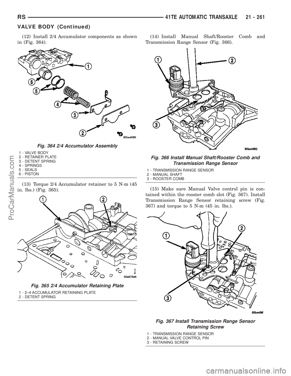
(12) Install 2/4 Accumulator components as shown
in (Fig. 364).
(13) Torque 2/4 Accumulator retainer to 5 N´m (45
in. lbs.) (Fig. 365).(14) Install Manual Shaft/Rooster Comb and
Transmission Range Sensor (Fig. 366).
(15) Make sure Manual Valve control pin is con-
tained within the rooster comb slot (Fig. 367). Install
Transmission Range Sensor retaining screw (Fig.
367) and torque to 5 N´m (45 in. lbs.).
Fig. 364 2/4 Accumulator Assembly
1 - VALVE BODY
2 - RETAINER PLATE
3 - DETENT SPRING
4 - SPRINGS
5 - SEALS
6 - PISTON
Fig. 365 2/4 Accumulator Retaining Plate
1 - 2±4 ACCUMULATOR RETAINING PLATE
2 - DETENT SPRING
Fig. 366 Install Manual Shaft/Rooster Comb and
Transmission Range Sensor
1 - TRANSMISSION RANGE SENSOR
2 - MANUAL SHAFT
3 - ROOSTER COMB
Fig. 367 Install Transmission Range Sensor
Retaining Screw
1 - TRANSMISSION RANGE SENSOR
2 - MANUAL VALVE CONTROL PIN
3 - RETAINING SCREW
RS41TE AUTOMATIC TRANSAXLE21 - 261
VALVE BODY (Continued)
ProCarManuals.com
Page 1709 of 2177
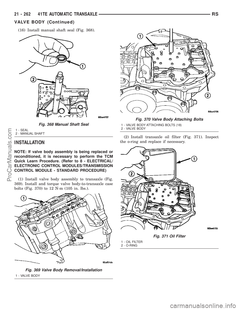
(16) Install manual shaft seal (Fig. 368).
INSTALLATION
NOTE: If valve body assembly is being replaced or
reconditioned, it is necessary to perform the TCM
Quick Learn Procedure. (Refer to 8 - ELECTRICAL/
ELECTRONIC CONTROL MODULES/TRANSMISSION
CONTROL MODULE - STANDARD PROCEDURE)
(1) Install valve body assembly to transaxle (Fig.
369). Install and torque valve body-to-transaxle case
bolts (Fig. 370) to 12 N´m (105 in. lbs.).(2) Install transaxle oil filter (Fig. 371). Inspect
the o-ring and replace if necessary.
Fig. 368 Manual Shaft Seal
1 - SEAL
2 - MANUAL SHAFT
Fig. 369 Valve Body Removal/Installation
1 - VALVE BODY
Fig. 370 Valve Body Attaching Bolts
1 - VALVE BODY ATTACHING BOLTS (18)
2 - VALVE BODY
Fig. 371 Oil Filter
1 - OIL FILTER
2 - O-RING
21 - 262 41TE AUTOMATIC TRANSAXLERS
VALVE BODY (Continued)
ProCarManuals.com
Page 1710 of 2177
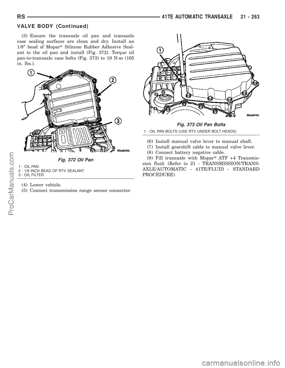
(3) Ensure the transaxle oil pan and transaxle
case sealing surfaces are clean and dry. Install an
1/8º bead of MopartSilicone Rubber Adhesive Seal-
ant to the oil pan and install (Fig. 372). Torque oil
pan-to-transaxle case bolts (Fig. 373) to 19 N´m (165
in. lbs.).
(4) Lower vehicle.
(5) Connect transmission range sensor connector.(6) Install manual valve lever to manual shaft.
(7) Install gearshift cable to manual valve lever.
(8) Connect battery negative cable.
(9) Fill transaxle with MopartATF +4 Transmis-
sion fluid. (Refer to 21 - TRANSMISSION/TRANS-
AXLE/AUTOMATIC - 41TE/FLUID - STANDARD
PROCEDURE)
Fig. 372 Oil Pan
1 - OIL PAN
2 - 1/8 INCH BEAD OF RTV SEALANT
3 - OIL FILTER
Fig. 373 Oil Pan Bolts
1 - OIL PAN BOLTS (USE RTV UNDER BOLT HEADS)
RS41TE AUTOMATIC TRANSAXLE21 - 263
VALVE BODY (Continued)
ProCarManuals.com
Trending: radio antenna, oil, diagram, tire size, air condition, flat tire, coolant reservoir
