fuel tank removal DODGE TOWN AND COUNTRY 2003 User Guide
[x] Cancel search | Manufacturer: DODGE, Model Year: 2003, Model line: TOWN AND COUNTRY, Model: DODGE TOWN AND COUNTRY 2003Pages: 2177, PDF Size: 59.81 MB
Page 1369 of 2177
(7) Remove fuel rail. Be careful not to damage the
injector O-rings upon removal from their ports.
INSTALLATION
INSTALLATION - 2.4L
(1) Ensure injector holes are clean. Replace
O-rings if damaged.
(2) Lubricate injector O-rings with a drop of clean
engine oil to ease installation.
(3) Put the tip of each injector into their ports.
Push the assembly into place until the injectors are
seated in the ports.
(4) Install the fuel rail mounting bolts. Tighten
bolts to 22 N´m (200 in. lbs.) torque.
(5) Connect the connectors to the fuel injectors.
(6) Install wiring harness to brackets.
(7) Connect the wiring connectors to fuel injectors
harness (Fig. 13).
(8) Connect negative battery cable.
(9) Use the DRBIIItscan tool to pressurize the
fuel system. Check for leaks.
INSTALLATION - 3.3/3.8L
(1) Ensure injector holes are clean. Replace
O-rings if damaged.
(2) Lubricate injector O-rings with a drop of clean
engine oil to ease installation.
(3) Put the tip of each injector into their ports.
Push the assembly into place until the injectors are
seated in the ports.
(4) Install the fuel rail mounting bolts. Tighten
bolts to 22 N´m (200 in. lbs.) torque.
(5) Remove covering on lower intake manifold and
clean surface.(6) Install the Upper Intake Manifold, refer to
Engine/Manifolds/Upper Intake for more information.
(7) Install fuel hose quick connector fitting to chas-
sis tubes.Refer to Fuel Hoses, Clamps and
Quick Connect Fittings in this Section.Push the
fitting onto the chassis tube until it clicks into place.
Pull on the fitting to ensure complete insertion.
(8) Connect negative cable to battery.
(9) Use the DRBIIItscan tool to pressurize the
fuel system. Check for leaks.
FUEL TANK
DESCRIPTION
The fuel tank is constructed of a plastic material.
Its main functions are for fuel storage and for place-
ment of the fuel pump module. The tank is made
from High density Polyethylene (HDPE) material.If
equipped with ORVR (Onboard Refueling Vapor
Recovery) it has been added to the fuel tank to con-
trol refueling vapor emissions.
OPERATION
All models pass a full 360 degree rollover test
without fuel leakage. To accomplish this, fuel and
vapor flow controls are required for all fuel tank con-
nections.
All models are equipped with either one or two
rollover valves mounted into the top of the fuel tank
(or pump module).
An evaporation control system is connected to the
rollover valve(s)/control valve(Refer to 25 - EMIS-
SIONS CONTROL/EVAPORATIVE EMISSIONS/
ORVR - OPERATION) to reduce emissions of fuel
vapors into the atmosphere, when the tank is vented
due to vapor expansion in the tank. When fuel evap-
orates from the fuel tank, vapors pass through vent
hoses or tubes to a charcoal canister where they are
temporarily held. When the engine is running, the
vapors are drawn into the intake manifold. In addi-
tion, fuel vapors produced during vehicle refueling
are allowed to pass through the vent hoses/tubes to
the charcoal canister(s) for temporary storage (prior
to being drawn into the intake manifold). All models
are equipped with a self-diagnosing system using a
Leak Detection Pump (LDP) or Natural Vacuum
Leak Detection (NVLD). Refer to the Emission Con-
trol System for additional information.
INLET CHECK VALVE
All vehicles have an inlet check valve on the inside
of the fuel tank at the filler inlet
The valve prevents fuel from splashing back on
customer during vehicle refueling. The valve is a
non-serviceable item.
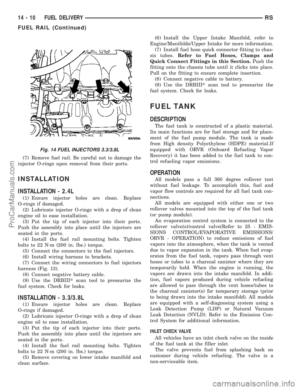
Fig. 14 FUEL INJECTORS 3.3/3.8L
14 - 10 FUEL DELIVERYRS
FUEL RAIL (Continued)
ProCarManuals.com
Page 1370 of 2177
REMOVAL
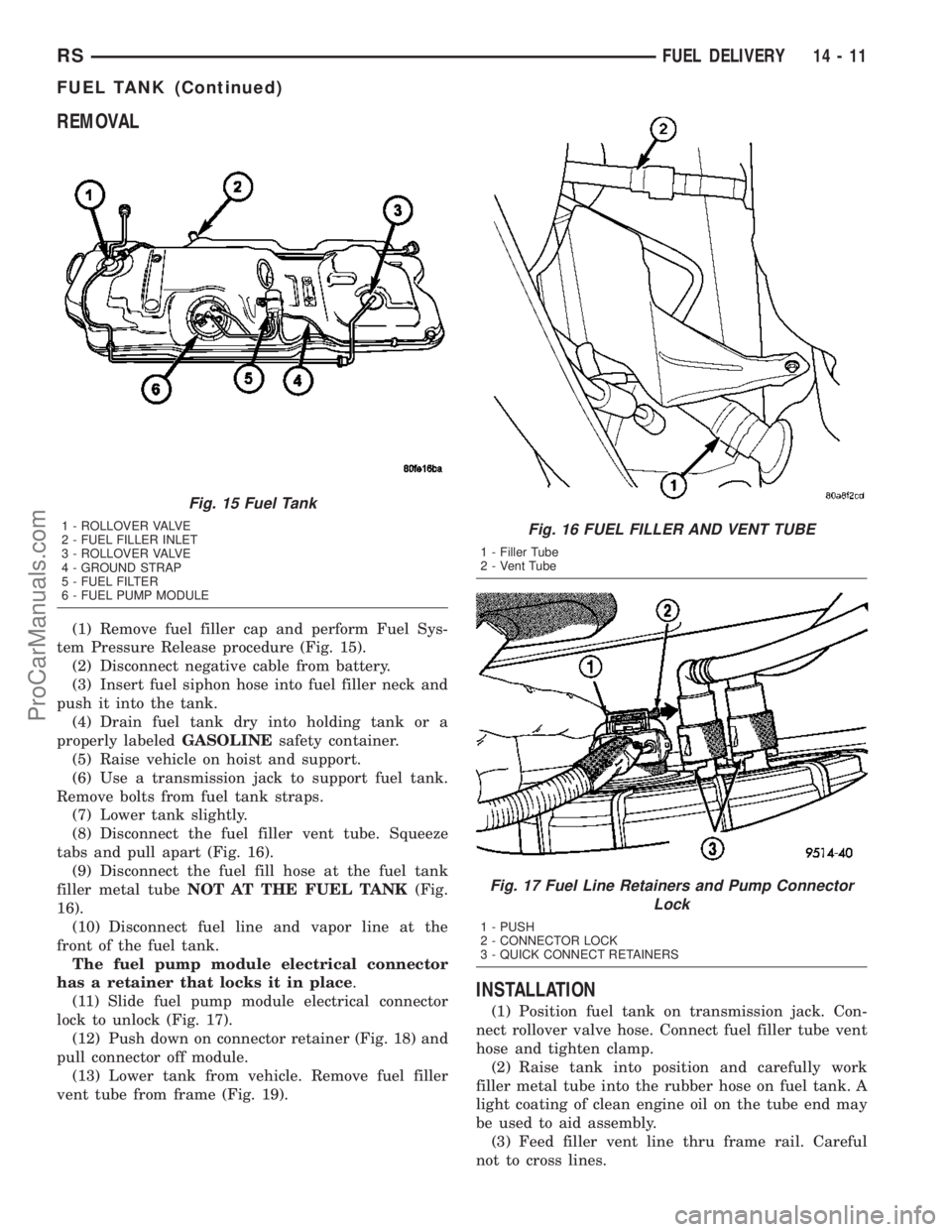
(1) Remove fuel filler cap and perform Fuel Sys-
tem Pressure Release procedure (Fig. 15).
(2) Disconnect negative cable from battery.
(3) Insert fuel siphon hose into fuel filler neck and
push it into the tank.
(4) Drain fuel tank dry into holding tank or a
properly labeledGASOLINEsafety container.
(5) Raise vehicle on hoist and support.
(6) Use a transmission jack to support fuel tank.
Remove bolts from fuel tank straps.
(7) Lower tank slightly.
(8) Disconnect the fuel filler vent tube. Squeeze
tabs and pull apart (Fig. 16).
(9) Disconnect the fuel fill hose at the fuel tank
filler metal tubeNOT AT THE FUEL TANK(Fig.
16).
(10) Disconnect fuel line and vapor line at the
front of the fuel tank.
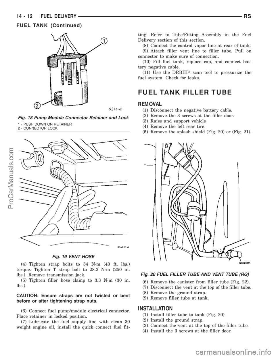
The fuel pump module electrical connector
has a retainer that locks it in place.
(11) Slide fuel pump module electrical connector
lock to unlock (Fig. 17).
(12) Push down on connector retainer (Fig. 18) and
pull connector off module.
(13) Lower tank from vehicle. Remove fuel filler
vent tube from frame (Fig. 19).
INSTALLATION
(1) Position fuel tank on transmission jack. Con-
nect rollover valve hose. Connect fuel filler tube vent
hose and tighten clamp.
(2) Raise tank into position and carefully work
filler metal tube into the rubber hose on fuel tank. A
light coating of clean engine oil on the tube end may
be used to aid assembly.
(3) Feed filler vent line thru frame rail. Careful
not to cross lines.
Fig. 15 Fuel Tank
1 - ROLLOVER VALVE
2 - FUEL FILLER INLET
3 - ROLLOVER VALVE
4 - GROUND STRAP
5 - FUEL FILTER
6 - FUEL PUMP MODULEFig. 16 FUEL FILLER AND VENT TUBE
1 - Filler Tube
2 - Vent Tube
Fig. 17 Fuel Line Retainers and Pump Connector
Lock
1 - PUSH
2 - CONNECTOR LOCK
3 - QUICK CONNECT RETAINERS
RSFUEL DELIVERY14-11
FUEL TANK (Continued)
ProCarManuals.com
Page 1371 of 2177
(4) Tighten strap bolts to 54 N´m (40 ft. lbs.)
torque. Tighten T strap bolt to 28.2 N´m (250 in.
lbs.). Remove transmission jack.
(5) Tighten filler hose clamp to 3.3 N´m (30 in.
lbs.).
CAUTION: Ensure straps are not twisted or bent
before or after tightening strap nuts.
(6) Connect fuel pump/module electrical connector.
Place retainer in locked position.
(7) Lubricate the fuel supply line with clean 30
weight engine oil, install the quick connect fuel fit-ting. Refer to Tube/Fitting Assembly in the Fuel
Delivery section of this section.
(8) Connect the control vapor line at rear of tank.
(9) Attach filler vent line to filler tube. Pull on
connector to make sure of connection.
(10) Fill fuel tank, replace cap, and connect bat-
tery negative cable.
(11) Use the DRBIIItscan tool to pressurize the
fuel system. Check for leaks.
FUEL TANK FILLER TUBE
REMOVAL
(1) Disconnect the negative battery cable.
(2) Remove the 3 screws at the filler door.
(3) Raise and support vehicle
(4) Remove the left rear tire.
(5) Remove the splash shield (Fig. 20) or (Fig. 21).
(6) Remove the canister from filler tube (Fig. 22).
(7) Disconnect the vent at the top of the filler tube.
(8) Remove the ground strap.
(9) Remove filler tube at tank.
INSTALLATION
(1) Install filler tube to tank (Fig. 20).
(2) Install the ground strap.
(3) Connect the vent at the top of the filler tube.
(4) Install the 3 screws at the filler door.
Fig. 18 Pump Module Connector Retainer and Lock
1 - PUSH DOWN ON RETAINER
2 - CONNECTOR LOCK
Fig. 19 VENT HOSE
Fig. 20 FUEL FILLER TUBE AND VENT TUBE (RG)
14 - 12 FUEL DELIVERYRS
FUEL TANK (Continued)
ProCarManuals.com
Page 1372 of 2177
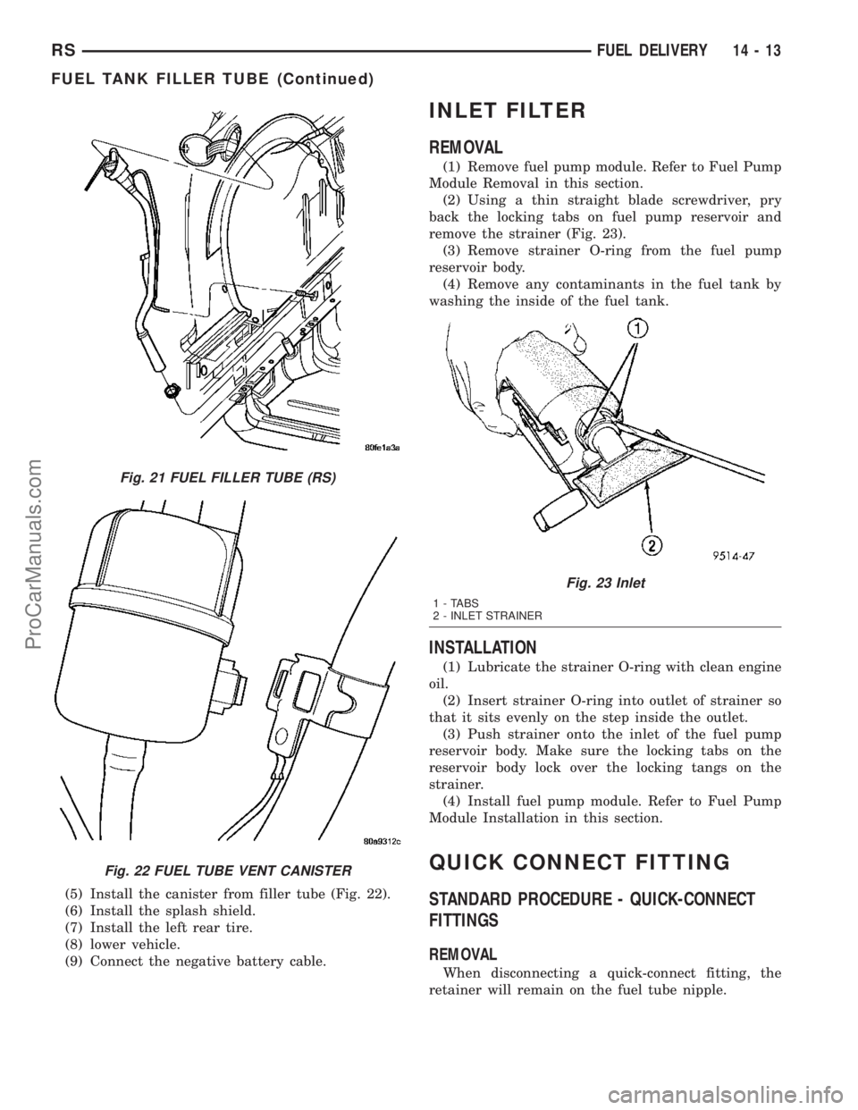
(5) Install the canister from filler tube (Fig. 22).
(6) Install the splash shield.
(7) Install the left rear tire.
(8) lower vehicle.
(9) Connect the negative battery cable.
INLET FILTER
REMOVAL
(1) Remove fuel pump module. Refer to Fuel Pump
Module Removal in this section.
(2) Using a thin straight blade screwdriver, pry
back the locking tabs on fuel pump reservoir and
remove the strainer (Fig. 23).
(3) Remove strainer O-ring from the fuel pump
reservoir body.
(4) Remove any contaminants in the fuel tank by
washing the inside of the fuel tank.
INSTALLATION
(1) Lubricate the strainer O-ring with clean engine
oil.
(2) Insert strainer O-ring into outlet of strainer so
that it sits evenly on the step inside the outlet.
(3) Push strainer onto the inlet of the fuel pump
reservoir body. Make sure the locking tabs on the
reservoir body lock over the locking tangs on the
strainer.
(4) Install fuel pump module. Refer to Fuel Pump
Module Installation in this section.
QUICK CONNECT FITTING
STANDARD PROCEDURE - QUICK-CONNECT
FITTINGS
REMOVAL
When disconnecting a quick-connect fitting, the
retainer will remain on the fuel tube nipple.
Fig. 21 FUEL FILLER TUBE (RS)
Fig. 22 FUEL TUBE VENT CANISTER
Fig. 23 Inlet
1 - TABS
2 - INLET STRAINER
RSFUEL DELIVERY14-13
FUEL TANK FILLER TUBE (Continued)
ProCarManuals.com
Page 1808 of 2177
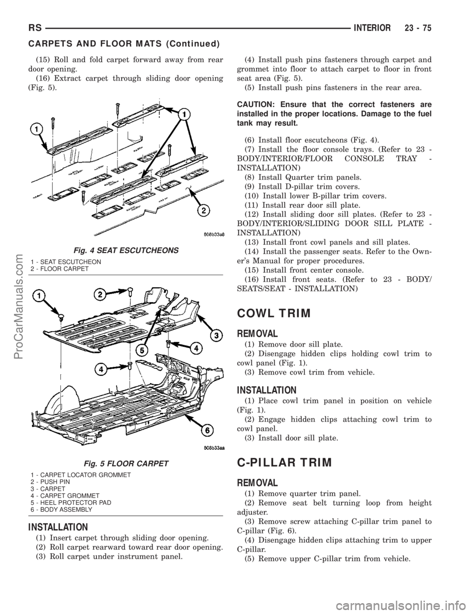
(15) Roll and fold carpet forward away from rear
door opening.
(16) Extract carpet through sliding door opening
(Fig. 5).
INSTALLATION
(1) Insert carpet through sliding door opening.
(2) Roll carpet rearward toward rear door opening.
(3) Roll carpet under instrument panel.(4) Install push pins fasteners through carpet and
grommet into floor to attach carpet to floor in front
seat area (Fig. 5).
(5) Install push pins fasteners in the rear area.
CAUTION: Ensure that the correct fasteners are
installed in the proper locations. Damage to the fuel
tank may result.
(6) Install floor escutcheons (Fig. 4).
(7) Install the floor console trays. (Refer to 23 -
BODY/INTERIOR/FLOOR CONSOLE TRAY -
INSTALLATION)
(8) Install Quarter trim panels.
(9) Install D-pillar trim covers.
(10) Install lower B-pillar trim covers.
(11) Install rear door sill plate.
(12) Install sliding door sill plates. (Refer to 23 -
BODY/INTERIOR/SLIDING DOOR SILL PLATE -
INSTALLATION)
(13) Install front cowl panels and sill plates.
(14) Install the passenger seats. Refer to the Own-
er's Manual for proper procedures.
(15) Install front center console.
(16) Install front seats. (Refer to 23 - BODY/
SEATS/SEAT - INSTALLATION)
COWL TRIM
REMOVAL
(1) Remove door sill plate.
(2) Disengage hidden clips holding cowl trim to
cowl panel (Fig. 1).
(3) Remove cowl trim from vehicle.
INSTALLATION
(1) Place cowl trim panel in position on vehicle
(Fig. 1).
(2) Engage hidden clips attaching cowl trim to
cowl panel.
(3) Install door sill plate.
C-PILLAR TRIM
REMOVAL
(1) Remove quarter trim panel.
(2) Remove seat belt turning loop from height
adjuster.
(3) Remove screw attaching C-pillar trim panel to
C-pillar (Fig. 6).
(4) Disengage hidden clips attaching trim to upper
C-pillar.
(5) Remove upper C-pillar trim from vehicle.
Fig. 4 SEAT ESCUTCHEONS
1 - SEAT ESCUTCHEON
2 - FLOOR CARPET
Fig. 5 FLOOR CARPET
1 - CARPET LOCATOR GROMMET
2 - PUSH PIN
3 - CARPET
4 - CARPET GROMMET
5 - HEEL PROTECTOR PAD
6 - BODY ASSEMBLY
RSINTERIOR23-75
CARPETS AND FLOOR MATS (Continued)
ProCarManuals.com
Page 2103 of 2177
DIESEL SUPPLEMENTAL HEATER - DCHA - EXPORT
TABLE OF CONTENTS
page page
DIESEL SUPPLEMENTAL HEATER - DCHA -
EXPORT
DESCRIPTION........................106
OPERATION
OPERATION........................106
OPERATION - TWO ZONE ATC..........106
DIAGNOSIS AND TESTING - DIESEL
SUPPLEMENTAL HEATER - DCHA.......107
EXHAUST TUBE
REMOVAL............................107
INSTALLATION........................107
FUEL DOSING PUMP
DESCRIPTION........................108
OPERATION..........................108
REMOVAL............................108INSTALLATION........................108
FUEL LINE
STANDARD PROCEDURE - CLEANING.....109
REMOVAL............................109
INSTALLATION........................110
HEATER UNIT
REMOVAL............................111
INSTALLATION........................111
SUPPLEMENTAL DIESEL HEATER WIRING
REMOVAL............................112
INSTALLATION........................112
AIR INTAKE PIPE
REMOVAL............................112
INSTALLATION........................113
DIESEL SUPPLEMENTAL
HEATER - DCHA - EXPORT
DESCRIPTION
Vehicles equipped with the optional diesel engine
are also equipped with a supplemental heater unit.
This unit is mounted under the vehicle and operates
similar to an oil fired furnace. The heater burns
small amounts of fuel to provide additional heat to
the coolant. Coolant is routed from the engine, to the
supplemental heater, and then to the front heater
core. This provides additional heat to the passenger
compartment. The system is interfaced to the vehi-
cles on-board computer systems and DRB-III diag-
nostics.
The supplemental heater unit has a electronic con-
trol unit that monitors the heat output of the heater.
The heater operates at full load (5 kW), half load or
idle mode (no additional heat) depending on collant
temperature.
OPERATION
OPERATION
The supplemental heater unit is activated via the
temperature slide control or knob on the vehicle
HVAC control unit. If the control slide or knob is
moved to or above the upper set point the heater is
activated. The unit can operate in a full or partial
load range as well as an idle mode all dependent on
the engine coolant temperature. The heater unit willalso turn off if the HVAC temperature control is low-
ered to less than the lower set point. The heater unit
can take up to three minutes to completely shut
down when either the heater temperature is set
below the lower set point or the vehicle ignition is
shut down.
The supplemental heater only operates when the
engine is running, the mileage exceeds 8 kilometer (5
mph) and the fuel tank volume exceeds 1/8 of a tank.
The heater should start if the collant temperature is
below 40 degrees celsius (104 degrees F).
NOTE: Do not apply a strong vacuum directly on
the supplemtal heater exhaust line. Place the vac-
uum within 75 mm (3 inches) of the exhaust port.
Too strong of a vacuum can prevent the heater from
starting. The heater ECU monitors the supplemental
blower speed and combustion during its start-up.
OPERATION - TWO ZONE ATC
The Two Zone ATC control head will activate the
Supplemental Heater based on engine coolant tem-
perature and interior component settings. The unit
can operate in a full or partial load range as well as
an idle mode all dependent on the engine coolant
temperature. The unit will also turn off if the HVAC
temperature control setting is lowered to less than
the lower set point. The unit can take up to three
minutes to completely shut down when either the
heater temperature is set below the lower set point of
the vehicle ignition is shut down.
24 - 106 DIESEL SUPPLEMENTAL HEATER - DCHA - EXPORTRS
ProCarManuals.com
Page 2104 of 2177
The supplemental heater only operates when the
engine is running, the mileage exceeds 8 kilometers
(5 mph) and the fuel tank volume exceeds 1/8 of a
tank. The heater should start if the coolant temper-
ature is below 40 degrees celsius (104 degrees F).
NOTE: Do not apply a strong vacuum directly on
the supplemental heater exhaust line. Place the vac-
uum within 75 mm (3 inches) of the exhaust outlet
port. Too strong of a vacuum can prevent the heaterfrom starting. The heater ECU monitors the supple-
mental blower speed and combustion during its
start-up.
DIAGNOSIS AND TESTING - DIESEL
SUPPLEMENTAL HEATER - DCHA
The following table lists possible fault symptoms of
diesel fueled heaters.
SYMPTOM POSSIBLE CAUSES
Smell of diesel fuel Check heater system integration in vehicle's fuel system. Check fuel
lines for leakage, kinks or obstructions. If OK, Inspect the inlet muffler,
drain as necessary. Re-test the unit and re-inspect. Inspect the
exhaust tube and heater unit for the presence of external fuel. If a
volume is observed on the unit or in the exhaust tube or after draining
and testing. Remove heater unit from vehicle and repair or replace
components as required.
Heater does not achieve full load
operation.Check heater operation with DRB-III and replace components as
required.
Continuous white smoke from heater
exhaust during combustion operation.Check heater operation with DRB-III and replace components as
required. White smoke is typical in extreme weather conditions.
Heater can not be switched off. Check heater operation with DRB-III and replace components as
required.
Heater does not operate. Diagnosis cabin heater ECU using the DRB-III and the procedures
listed in Vehicle Performance under Cabin Heater Diagnosis in Group
18.
Loss of coolant (Leakage) or heater
develops smoke during combustion
operation and exhaust has an
extremely sweet smell.Inspect coolant hoses for leakage, kinks or loose hose connection.
Inspect the exhaust tube assembly for continuous flow, if OK there is
an internal heater leak and unit should be inspected and components
should be replaced as required.
Loss of fuel (dripping). Check heater system integration in vehicles fuel system. Check fuel
line connection for leakage. If OK there is an internal leak and unit
should be inspected and replaced as required.
EXHAUST TUBE
REMOVAL
WARNING: THERE IS A POTENTIAL DANGER OF
SKIN BURNS AS THE HEATER AND ITS COMPO-
NENTS MAY BE VERY HOT. MAKE SURE THE
HEATER IS ALLOWED TO COOL DOWN BEFORE
ANY SERVICE WORK ON THE CABIN HEATER SYS-
TEM IS ATTEMPTED.
(1) Elevate vehicle on a lift taking note of the
exhaust tube flexible section.
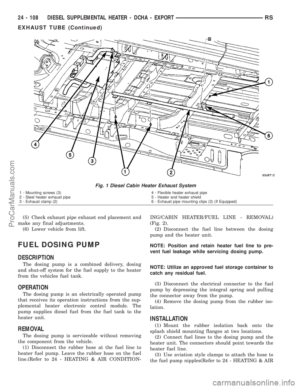
(2) Remove the exhaust clamp at the flexible pipe
and steel pipe connection (Fig. 1).
(3) Remove the clamp at the flexible pipe connec-
tion and the heater unit housing (if required).(4) Remove the three screws holding the exhaust
pipe to the body.
(5) Remove the steel exhaust pipe from the vehi-
cle.
(6) Remove the flexible exhaust pipe from the
vehicle (if required).
INSTALLATION
(1) Install the flexible exhaust pipe to the heater
unit. Tighten mounting clamp.
(2) Position the steel exhaust pipe to the flexible
exhaust and install and tighten the mounting clamp.
(3) Install the three exhaust pipe screws, adjust
pipe placement as needed and tighten the screws.
(4) Install the clamp to connect the steel exhaust
pipe to the flexible exhaust pipe and tighten clamp.
RSDIESEL SUPPLEMENTAL HEATER - DCHA - EXPORT24 - 107
DIESEL SUPPLEMENTAL HEATER - DCHA - EXPORT (Continued)
ProCarManuals.com
Page 2105 of 2177
(5) Check exhaust pipe exhaust end placement and
make any final adjustments.
(6) Lower vehicle from lift.
FUEL DOSING PUMP
DESCRIPTION
The dosing pump is a combined delivery, dosing
and shut-off system for the fuel supply to the heater
from the vehicles fuel tank.
OPERATION
The dosing pump is an electrically operated pump
that receives its operation instructions from the sup-
plemental heater electronic control module. The
pump supplies diesel fuel from the fuel tank to the
heater unit.
REMOVAL
The dosing pump is serviceable without removing
the component from the vehicle.
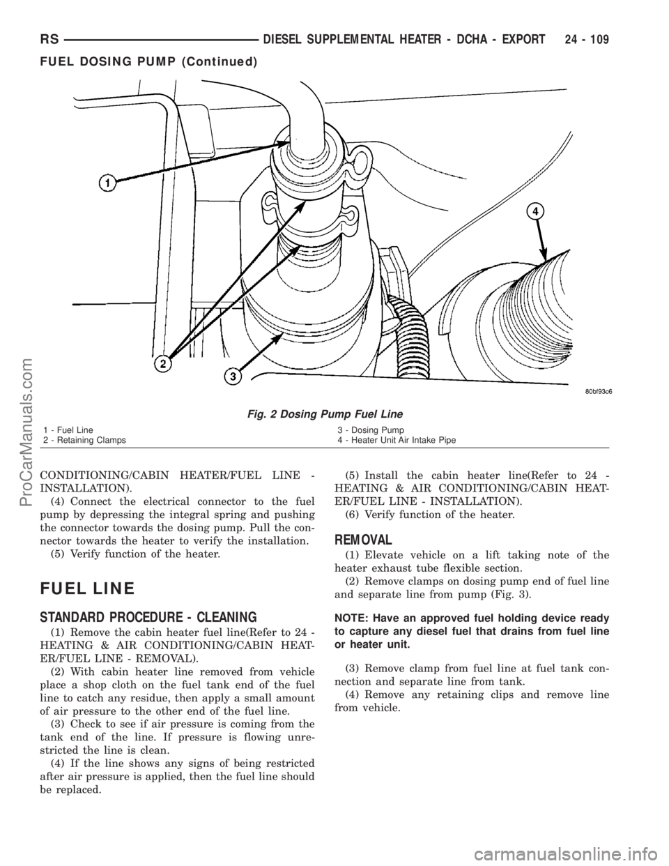
(1) Disconnect the rubber hose at the fuel line to
heater fuel pump. Leave the rubber hose on the fuel
line.(Refer to 24 - HEATING & AIR CONDITION-ING/CABIN HEATER/FUEL LINE - REMOVAL)
(Fig. 2).
(2) Disconnect the fuel line between the dosing
pump and the heater unit.
NOTE: Position and retain heater fuel line to pre-
vent fuel leakage while servicing dosing pump.
NOTE: Utilize an approved fuel storage container to
catch any residual fuel.
(3) Disconnect the electrical connector to the fuel
pump by depressing the integral spring and pulling
the connector away from the pump.
(4) Remove the dosing pump from the rubber iso-
lation.
INSTALLATION
(1) Mount the rubber isolation back onto the
splash shield mounting flanges at two locations.
(2) Connect fuel lines to the dosing pump and the
heater unit. The connectors should point towards the
heater fuel line.
(3) Use aviation style clamps to attach the hose to
the fuel pump nipples(Refer to 24 - HEATING & AIR
Fig. 1 Diesel Cabin Heater Exhaust System
1 - Mounting screws (3)
2 - Steel heater exhaust pipe
3 - Exhaust clamp (2)4 - Flexible heater exhaust pipe
5 - Heater and heater shield
6 - Exhaust pipe mounting clips (3) (If Equipped)
24 - 108 DIESEL SUPPLEMENTAL HEATER - DCHA - EXPORTRS
EXHAUST TUBE (Continued)
ProCarManuals.com
Page 2106 of 2177
CONDITIONING/CABIN HEATER/FUEL LINE -
INSTALLATION).
(4) Connect the electrical connector to the fuel
pump by depressing the integral spring and pushing
the connector towards the dosing pump. Pull the con-
nector towards the heater to verify the installation.
(5) Verify function of the heater.
FUEL LINE
STANDARD PROCEDURE - CLEANING
(1) Remove the cabin heater fuel line(Refer to 24 -
HEATING & AIR CONDITIONING/CABIN HEAT-
ER/FUEL LINE - REMOVAL).
(2) With cabin heater line removed from vehicle
place a shop cloth on the fuel tank end of the fuel
line to catch any residue, then apply a small amount
of air pressure to the other end of the fuel line.
(3) Check to see if air pressure is coming from the
tank end of the line. If pressure is flowing unre-
stricted the line is clean.
(4) If the line shows any signs of being restricted
after air pressure is applied, then the fuel line should
be replaced.(5) Install the cabin heater line(Refer to 24 -
HEATING & AIR CONDITIONING/CABIN HEAT-
ER/FUEL LINE - INSTALLATION).
(6) Verify function of the heater.
REMOVAL
(1) Elevate vehicle on a lift taking note of the
heater exhaust tube flexible section.
(2) Remove clamps on dosing pump end of fuel line
and separate line from pump (Fig. 3).
NOTE: Have an approved fuel holding device ready
to capture any diesel fuel that drains from fuel line
or heater unit.
(3) Remove clamp from fuel line at fuel tank con-
nection and separate line from tank.
(4) Remove any retaining clips and remove line
from vehicle.
Fig. 2 Dosing Pump Fuel Line
1 - Fuel Line
2 - Retaining Clamps3 - Dosing Pump
4 - Heater Unit Air Intake Pipe
RSDIESEL SUPPLEMENTAL HEATER - DCHA - EXPORT24 - 109
FUEL DOSING PUMP (Continued)
ProCarManuals.com
Page 2121 of 2177
EVAPORATIVE EMISSIONS
TABLE OF CONTENTS
page page
EVAPORATIVE EMISSIONS
OPERATION - EVAPORATION CONTROL
SYSTEM............................10
SPECIFICATIONS
TORQUE............................11
EVAP/PURGE SOLENOID
DESCRIPTION.........................12
OPERATION...........................12
REMOVAL.............................12
INSTALLATION.........................12
FUEL FILLER CAP
DESCRIPTION.........................12
OPERATION...........................12
NATURAL VAC LEAK DETECTION ASSY
REMOVAL.............................13
INSTALLATION.........................13
LEAK DETECTION PUMP
REMOVAL.............................13
INSTALLATION.........................13ORVR
OPERATION...........................14
DIAGNOSIS AND TESTING - VEHICLE DOES
NOT FILL............................16
P C V VA LV E
DESCRIPTION.........................16
OPERATION...........................16
DIAGNOSIS AND TESTING - PCV SYSTEM . . . 17
VAPOR CANISTER
DESCRIPTION.........................18
OPERATION...........................18
REMOVAL
REMOVAL...........................18
REMOVAL - WITH NVLD................19
REMOVAL - REAR EVAP CANISTER.......19
INSTALLATION
INSTALLATION.......................19
INSTALLATION - WITH NVLD............20
INSTALLATION - REAR EVAP CANISTER . . . 20
EVAPORATIVE EMISSIONS
OPERATION - EVAPORATION CONTROL
SYSTEM
The evaporation control system prevents the emis-
sion of fuel tank vapors into the atmosphere. When
fuel evaporates in the fuel tank, the vapors pass
through vent hoses or tubes to an activated carbon
filled evaporative canister. The canister temporarily
holds the vapors. The Powertrain Control Module
(PCM) allows intake manifold vacuum to draw
vapors into the combustion chambers during certain
operating conditions (Fig. 1).All engines use a proportional purge solenoid sys-
tem. The PCM controls vapor flow by operating the
purge solenoid. Refer to Proportional Purge Solenoid
in this section.
NOTE: The evaporative system uses specially man-
ufactured hoses. If they need replacement, only use
fuel resistant hose. Also the hoses must be able to
pass an Ozone compliance test.
NOTE: For more information on Onboard Refueling
Vapor Recovery (ORVR), refer to the Fuel Delivery
section.
25 - 10 EVAPORATIVE EMISSIONSRS
ProCarManuals.com