transmission oil DODGE TOWN AND COUNTRY 2003 Owner's Guide
[x] Cancel search | Manufacturer: DODGE, Model Year: 2003, Model line: TOWN AND COUNTRY, Model: DODGE TOWN AND COUNTRY 2003Pages: 2177, PDF Size: 59.81 MB
Page 419 of 2177
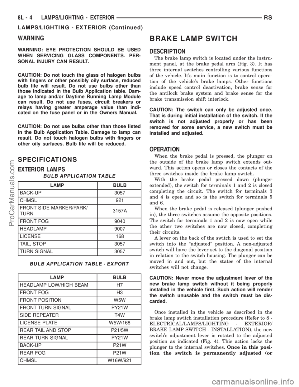
WARNING
WARNING: EYE PROTECTION SHOULD BE USED
WHEN SERVICING GLASS COMPONENTS. PER-
SONAL INJURY CAN RESULT.
CAUTION: Do not touch the glass of halogen bulbs
with fingers or other possibly oily surface, reduced
bulb life will result. Do not use bulbs other than
those indicated in the Bulb Application table. Dam-
age to lamp and/or Daytime Running Lamp Module
can result. Do not use fuses, circuit breakers or
relays having greater amperage value than indi-
cated on the fuse panel or in the Owners Manual.
CAUTION: Do not use bulbs other than those listed
in the Bulb Application Table. Damage to lamp can
result. Do not touch halogen bulbs with fingers or
other oily surfaces. Bulb life will be reduced.
SPECIFICATIONS
EXTERIOR LAMPS
BULB APPLICATION TABLE
LAMP BULB
BACK-UP 3057
CHMSL 921
FRONT SIDE MARKER/PARK/
TURN3157A
FRONT FOG 9040
HEADLAMP 9007
LICENSE 168
TAIL, STOP 3057
TURN SIGNAL 3057
BULB APPLICATION TABLE - EXPORT
LAMP BULB
HEADLAMP LOW/HIGH BEAM H7
FRONT FOG H3
FRONT POSITION W5W
FRONT TURN SIGNAL PY21W
SIDE REPEATER T4W
LICENSE PLATE W5W/168
REAR TAIL AND STOP P21/5W
REAR TURN SIGNAL PY21W
BACK-UP P21W
REAR FOG P21W
CHMSL W16W/921
BRAKE LAMP SWITCH
DESCRIPTION
The brake lamp switch is located under the instru-
ment panel, at the brake pedal arm (Fig. 3). It has
three internal switches controlling various functions
of the vehicle. It's main function is to control opera-
tion of the vehicle's brake lamps. Other functions
include speed control deactivation, brake sense for
the antilock brake system and brake sense for the
brake transmission shift interlock.
CAUTION: The switch can only be adjusted once.
That is during initial installation of the switch. If the
switch is not adjusted properly or has been
removed for some service, a new switch must be
installed and adjusted.
OPERATION
When the brake pedal is pressed, the plunger on
the outside of the brake lamp switch extends out-
ward. This action opens or closes the contacts of the
three switches inside the brake lamp switch.
With the brake pedal pressed down (plunger
extended), the switch for terminals 1 and 2 is closed
completing the circuit. The switch for terminals 3
and 4 is open and so is the switch for terminals 5
and 6.
When the brake pedal is released (plunger pushed
in), the three switches assume the opposite positions.
The switch for terminals 1 and 2 is now open while
the other two switches are now closed, completing
their circuits.
A lever on the back of the switch is used to set the
switch into the ªadjustedº position. A non-adjusted
switch will have the lever set to the diagonal position
in relation to the switch housing. The plunger can be
moved in and out, but the states of the internal
switches will not change.
CAUTION: Never move the adjustment lever of the
new brake lamp switch without it being properly
installed in the vehicle first. Such action will render
the switch unusable and the switch must be dis-
carded.
Once installed in the vehicle as described in the
brake lamp switch installation procedure (Refer to 8 -
ELECTRICAL/LAMPS/LIGHTING - EXTERIOR/
BRAKE LAMP SWITCH - INSTALLATION), the new
switch's adjustment lever is rotated to the adjusted
position as indicated (Fig. 4). This action locks the
plunger to the internal switches.Once in this posi-
tion the switch is permanently adjusted (or
8L - 4 LAMPS/LIGHTING - EXTERIORRS
LAMPS/LIGHTING - EXTERIOR (Continued)
ProCarManuals.com
Page 588 of 2177
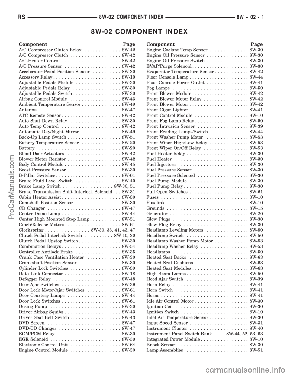
8W-02 COMPONENT INDEX
Component Page
A/C Compressor Clutch Relay............. 8W-42
A/C Compressor Clutch.................. 8W-42
A/C-Heater Control..................... 8W-42
A/C Pressure Sensor.................... 8W-42
Accelerator Pedal Position Sensor.......... 8W-30
Accessory Relay........................ 8W-10
Adjustable Pedals Module................ 8W-30
Adjustable Pedals Relay................. 8W-30
Adjustable Pedals Switch................. 8W-30
Airbag Control Module.................. 8W-43
Ambient Temperature Sensor.............. 8W-49
Antenna............................. 8W-47
ATC Remote Sensor..................... 8W-42
Auto Shut Down Relay.................. 8W-30
Auto Temp Control..................... 8W-42
Automatic Day/Night Mirror.............. 8W-49
Back-Up Lamp Switch................... 8W-51
Battery Temperature Sensor.............. 8W-20
Battery.............................. 8W-20
Blend Door Actuators................... 8W-42
Blower Motor Resistor................... 8W-42
Body Control Module.................... 8W-45
Boost Pressure Sensor................... 8W-30
B-Pillar Switches....................... 8W-61
Brake Fluid Level Switch................ 8W-40
Brake Lamp Switch.................. 8W-30, 51
Brake Transmission Shift Interlock Solenoid . . 8W-31
Cabin Heater Assist..................... 8W-30
Camshaft Position Sensor................ 8W-30
CD Changer.......................... 8W-47
Center Dome Lamp..................... 8W-44
Center High Mounted Stop Lamp........... 8W-51
Cinch/Release Motors................... 8W-61
Clockspring................ 8W-30, 33, 41, 43, 47
Clutch Pedal Interlock Switch.......... 8W-10, 30
Clutch Pedal Upstop Switch............... 8W-30
Combination Relays..................... 8W-54
Controller Antilock Brake................ 8W-35
Crank Case Ventilation Heater............ 8W-30
Crankshaft Position Sensor............... 8W-30
Cylinder Lock Switches.................. 8W-39
Data Link Connector.................... 8W-18
Defogger Relay........................ 8W-48
Door Ajar Switches..................... 8W-39
Door Lock Motor/Ajar Switches............ 8W-61
Door Courtesy Lamps................... 8W-44
Door Lock Switches..................... 8W-61
Dosing Pump......................... 8W-30
Driver Airbag Squibs.................... 8W-43
Driver Seat Belt Switch.................. 8W-43
DVD Screen.......................... 8W-47
DVD/CD Changer...................... 8W-47
ECM/PCM Relay....................... 8W-30
EGR Solenoid......................... 8W-30
Electronic Control Unit.................. 8W-64
Engine Control Module.................. 8W-30
Component Page
Engine Coolant Temp Sensor.............. 8W-30
Engine Oil Pressure Sensor............... 8W-30
Engine Oil Pressure Switch............... 8W-30
EVAP/Purge Solenoid.................... 8W-30
Evaporator Temperature Sensor............ 8W-42
Floor Console Lamp..................... 8W-44
Floor Console Power Outlet............... 8W-41
Fog Lamps........................... 8W-50
Front Blower Module.................... 8W-42
Front Blower Motor Relay................ 8W-42
Front Blower Motor..................... 8W-42
Front Cigar Lighter..................... 8W-41
Front Control Module................... 8W-10
Front Fog Lamp Relay................... 8W-50
Front Intrusion Sensor.................. 8W-39
Front Reading Lamps/Switch.............. 8W-44
Front Washer Pump Motor............... 8W-53
Front Wiper High/Low Relay.............. 8W-53
Front Wiper On/Off Relay................ 8W-53
Fuel Heater Relay...................... 8W-30
Fuel Heater.......................... 8W-30
Fuel Injectors......................... 8W-30
Fuel Pressure Sensor.................... 8W-30
Fuel Pressure Solenoid.................. 8W-30
Fuel Pump Module..................... 8W-30
Fuel Pump Relay....................... 8W-30
Full Open Switches..................... 8W-61
Fuses............................... 8W-10
Fuselink............................. 8W-10
Grounds............................. 8W-15
Generator............................ 8W-20
Glow Plugs........................... 8W-30
Glow Plug Relay....................... 8W-30
Headlamp Leveling Motors............... 8W-50
Headlamp Switch...................... 8W-50
Headlamp Washer Pump Motor............ 8W-53
Headlamp Washer Relay................. 8W-53
Headlamps........................... 8W-50
Heated Seat Backs..................... 8W-63
Heated Seat Cushions................... 8W-63
Heated Seat Modules.................... 8W-63
High Beam Lamps...................... 8W-50
Hood Ajar Switch...................... 8W-39
Horn Relay........................... 8W-41
Horn Switch.......................... 8W-41
Horns............................... 8W-41
Idle Air Control Motor................... 8W-30
Ignition Coil.......................... 8W-30
Ignition Switch........................ 8W-10
Inlet Air Temperature Sensor.............. 8W-30
Input Speed Sensor..................... 8W-31
Instrument Cluster..................... 8W-40
Instrument Panel Switch Bank.... 8W-44, 52, 53, 63
Integrated Power Module................. 8W-10
Knock Sensor......................... 8W-30
Lamp Assemblies...................... 8W-51
RS8W-02 COMPONENT INDEX8W-02-1
ProCarManuals.com
Page 591 of 2177
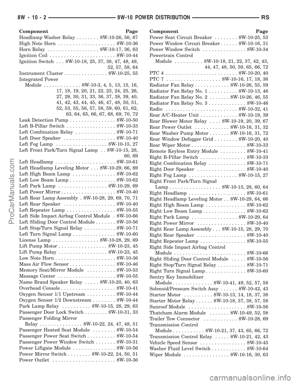
Component Page
Headlamp Washer Relay........ 8W-10-26, 56, 67
High Note Horn.................... 8W-10-36
Horn Relay.................. 8W-10-17, 36, 63
Ignition Coil....................... 8W-10-44
Ignition Switch . . . 8W-10-18, 25, 37, 38, 47, 48, 49,
52, 57, 58, 64
Instrument Cluster............... 8W-10-25, 55
Integrated Power
Module............. 8W-10-3, 4, 5, 13, 15, 16,
17, 18, 19, 20, 21, 22, 23, 24, 25, 26,
27, 29, 30, 31, 33, 36, 37, 38, 39, 40,
41, 42, 43, 44, 45, 46, 47, 48, 50, 51,
52, 53, 55, 56, 57, 58, 59, 60, 61, 62,
63, 64, 65, 66, 67, 68, 69, 70, 72
Leak Detection Pump................ 8W-10-50
Left B-Pillar Switch................. 8W-10-33
Left Combination Relay.............. 8W-10-71
Left Door Speaker.................. 8W-10-40
Left Fog Lamp.................. 8W-10-15, 27
Left Front Park/Turn Signal Lamp . . 8W-10-15, 28,
60, 69
Left Headlamp..................... 8W-10-61
Left Headlamp Leveling Motor . . . 8W-10-29, 66, 69
Left High Beam Lamp............... 8W-10-62
Left Low Beam Lamp................ 8W-10-62
Left Park Lamp................. 8W-10-29, 69
Left Power Mirror................... 8W-10-40
Left Rear Lamp Assembly . 8W-10-28, 29, 69, 70, 71
Left Rear Speaker.................. 8W-10-40
Left Repeater Lamp................. 8W-10-55
Left Side Impact Airbag Control Module . 8W-10-66
Left Sliding Door Control Module....... 8W-10-56
Left Stop/Turn Signal Relay........... 8W-10-71
Left Turn Signal Lamp............... 8W-10-60
License Lamp................ 8W-10-28, 29, 69
Lift Pump Motor................. 8W-10-23, 45
Lift Pump Relay................. 8W-10-23, 45
Low Note Horn..................... 8W-10-36
Mass Air Flow Sensor................ 8W-10-46
Memory Seat/Mirror Module.......... 8W-10-53
Message Center.................... 8W-10-55
Name Brand Speaker Relay..... 8W-10-20, 40, 63
Overhead Console................... 8W-10-41
Oxygen Sensor 1/1 Upstream.......... 8W-10-44
Oxygen Sensor 1/2 Downstream........ 8W-10-44
Park Lamp Relay.......... 8W-10-15, 28, 29, 63
Passenger Door Lock Switch........ 8W-10-31, 33
Passenger Folding Mirror
Relay............... 8W-10-22, 24, 47, 48, 51
Passenger Heated Seat Module........ 8W-10-54
Passenger Power Seat Switch.......... 8W-10-54
Passenger Power Window Switch....... 8W-10-31
Power Liftgate Module............... 8W-10-56
Power Mirror Switch........ 8W-10-22, 24, 50, 51
Power Outlet...................... 8W-10-36Component Page
Power Seat Circuit Breaker........ 8W-10-25, 53
Power Window Circuit Breaker...... 8W-10-16, 31
Power Window Switch............... 8W-10-34
Powertrain Control
Module.......... 8W-10-18, 21, 22, 37, 42, 43,
44, 47, 48, 50, 59, 65, 66, 72
PTC4 ......................... 8W-10-20, 40
PTC7 ................... 8W-10-16, 17, 18, 36
Radiator Fan Relay............ 8W-10-26, 55, 59
Radiator Fan Relay No. 1.......... 8W-10-13, 46
Radiator Fan Relay No. 2....... 8W-10-26, 46, 55
Radiator Fan Relay No. 3............. 8W-10-46
Radio......................... 8W-10-32, 41
Rear A/C-Heater Unit............. 8W-10-19, 39
Rear Blower Motor Relay.... 8W-10-19, 20, 39, 67
Rear Power Outlet............ 8W-10-16, 31, 32
Rear Washer Pump Motor....... 8W-10-16, 31, 72
Rear Window Defogger Grid........ 8W-10-20, 40
Rear Wiper Motor................... 8W-10-33
Remote Keyless Entry Module......... 8W-10-41
Right B-Pillar Switch................ 8W-10-33
Right Combination Relay............. 8W-10-71
Right Door Speaker................. 8W-10-40
Right Fog Lamp................. 8W-10-15, 27
Right Front Park/Turn Signal
Lamp.................. 8W-10-15, 28, 60, 64
Right Headlamp.................... 8W-10-61
Right Headlamp Leveling Motor . . 8W-10-29, 64, 66
Right High Beam Lamp.............. 8W-10-62
Right Low Beam Lamp............... 8W-10-62
Right Park Lamp................ 8W-10-29, 64
Right Power Mirror................. 8W-10-40
Right Rear Lamp Assembly . . . 8W-10-15, 28, 29, 70
Right Rear Speaker................. 8W-10-40
Right Repeater Lamp................ 8W-10-55
Right Side Impact Airbag Control
Module......................... 8W-10-66
Right Sliding Door Control Module..... 8W-10-56
Right Stop/Turn Signal Relay.......... 8W-10-71
Right Turn Signal Lamp.............. 8W-10-60
Sentry Key Immobilizer
Module.............. 8W-10-41, 49, 52, 57, 58
Solenoid/Pressure Switch Assy...... 8W-10-42, 43
Starter Motor.......... 8W-10-13, 14, 18, 37, 38
Starter Motor Relay...... 8W-10-18, 37, 38, 57, 58
Sunroof Module.................... 8W-10-56
Thatcham Alarm Module....... 8W-10-49, 52, 58
Trailer Tow Connector............ 8W-10-28, 69
Transmission Control
Module........... 8W-10-21, 37, 43, 65, 66, 72
Transmission Control Relay..... 8W-10-21, 42, 43
Vehicle Speed Sensor................ 8W-10-45
Washer Fluid Level Switch............ 8W-10-64
Wiper Module................ 8W-10-16, 30, 63
8W - 10 - 2 8W-10 POWER DISTRIBUTIONRS
ProCarManuals.com
Page 706 of 2177
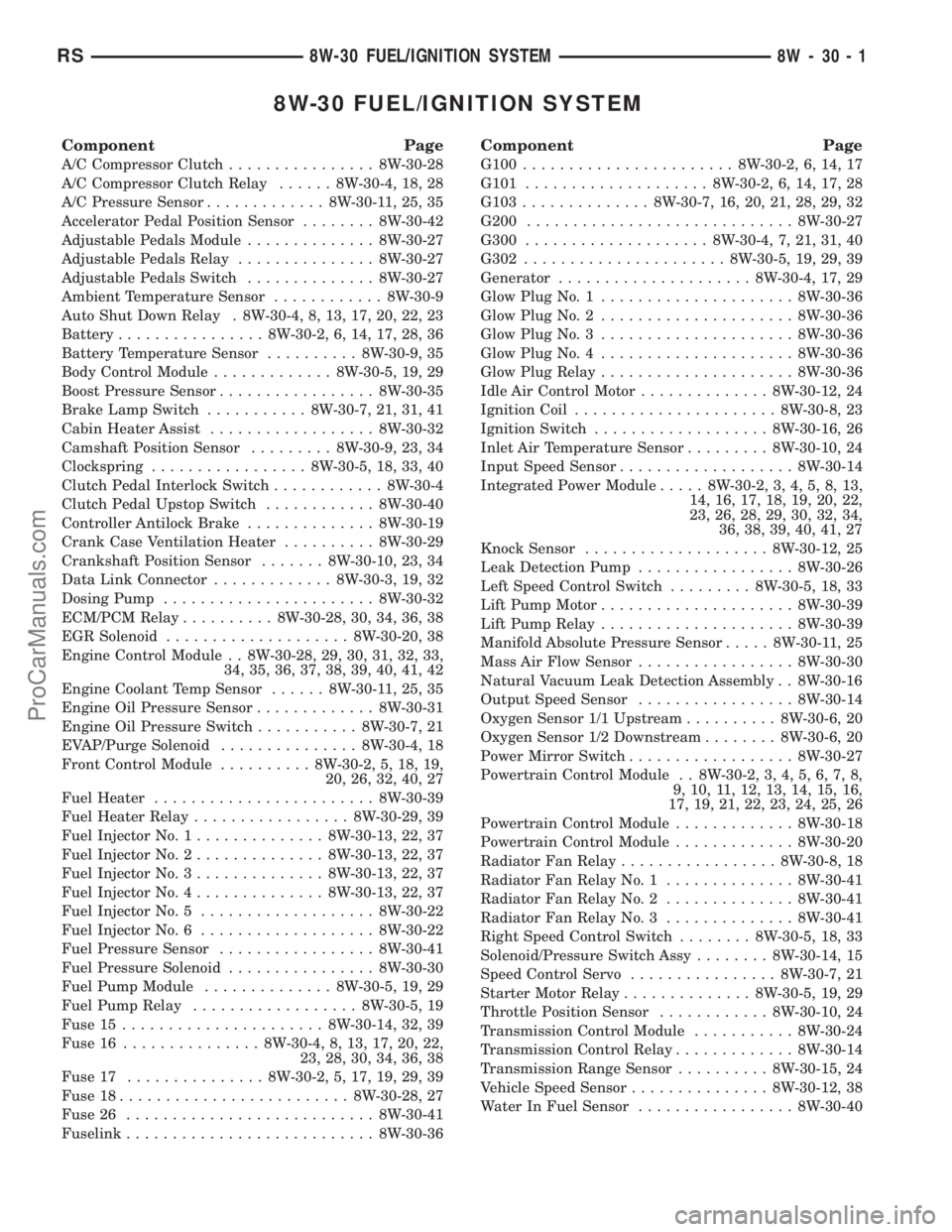
8W-30 FUEL/IGNITION SYSTEM
Component Page
A/C Compressor Clutch................ 8W-30-28
A/C Compressor Clutch Relay...... 8W-30-4, 18, 28
A/C Pressure Sensor............. 8W-30-11, 25, 35
Accelerator Pedal Position Sensor........ 8W-30-42
Adjustable Pedals Module.............. 8W-30-27
Adjustable Pedals Relay............... 8W-30-27
Adjustable Pedals Switch.............. 8W-30-27
Ambient Temperature Sensor............ 8W-30-9
Auto Shut Down Relay . 8W-30-4, 8, 13, 17, 20, 22, 23
Battery................ 8W-30-2, 6, 14, 17, 28, 36
Battery Temperature Sensor.......... 8W-30-9, 35
Body Control Module............. 8W-30-5, 19, 29
Boost Pressure Sensor................. 8W-30-35
Brake Lamp Switch........... 8W-30-7, 21, 31, 41
Cabin Heater Assist.................. 8W-30-32
Camshaft Position Sensor......... 8W-30-9, 23, 34
Clockspring................. 8W-30-5, 18, 33, 40
Clutch Pedal Interlock Switch............ 8W-30-4
Clutch Pedal Upstop Switch............ 8W-30-40
Controller Antilock Brake.............. 8W-30-19
Crank Case Ventilation Heater.......... 8W-30-29
Crankshaft Position Sensor....... 8W-30-10, 23, 34
Data Link Connector............. 8W-30-3, 19, 32
Dosing Pump....................... 8W-30-32
ECM/PCM Relay.......... 8W-30-28, 30, 34, 36, 38
EGR Solenoid.................... 8W-30-20, 38
Engine Control Module . . 8W-30-28, 29, 30, 31, 32, 33,
34, 35, 36, 37, 38, 39, 40, 41, 42
Engine Coolant Temp Sensor...... 8W-30-11, 25, 35
Engine Oil Pressure Sensor............. 8W-30-31
Engine Oil Pressure Switch........... 8W-30-7, 21
EVAP/Purge Solenoid............... 8W-30-4, 18
Front Control Module.......... 8W-30-2, 5, 18, 19,
20, 26, 32, 40, 27
Fuel Heater........................ 8W-30-39
Fuel Heater Relay................. 8W-30-29, 39
Fuel Injector No. 1.............. 8W-30-13, 22, 37
Fuel Injector No. 2.............. 8W-30-13, 22, 37
Fuel Injector No. 3.............. 8W-30-13, 22, 37
Fuel Injector No. 4.............. 8W-30-13, 22, 37
Fuel Injector No. 5................... 8W-30-22
Fuel Injector No. 6................... 8W-30-22
Fuel Pressure Sensor................. 8W-30-41
Fuel Pressure Solenoid................ 8W-30-30
Fuel Pump Module.............. 8W-30-5, 19, 29
Fuel Pump Relay.................. 8W-30-5, 19
Fuse 15...................... 8W-30-14, 32, 39
Fuse 16............... 8W-30-4, 8, 13, 17, 20, 22,
23, 28, 30, 34, 36, 38
Fuse 17............... 8W-30-2, 5, 17, 19, 29, 39
Fuse 18......................... 8W-30-28, 27
Fuse 26........................... 8W-30-41
Fuselink........................... 8W-30-36
Component Page
G100....................... 8W-30-2, 6, 14, 17
G101.................... 8W-30-2, 6, 14, 17, 28
G103.............. 8W-30-7, 16, 20, 21, 28, 29, 32
G200............................. 8W-30-27
G300.................... 8W-30-4, 7, 21, 31, 40
G302...................... 8W-30-5, 19, 29, 39
Generator..................... 8W-30-4, 17, 29
Glow Plug No. 1..................... 8W-30-36
Glow Plug No. 2..................... 8W-30-36
Glow Plug No. 3..................... 8W-30-36
Glow Plug No. 4..................... 8W-30-36
Glow Plug Relay..................... 8W-30-36
Idle Air Control Motor.............. 8W-30-12, 24
Ignition Coil...................... 8W-30-8, 23
Ignition Switch................... 8W-30-16, 26
Inlet Air Temperature Sensor......... 8W-30-10, 24
Input Speed Sensor................... 8W-30-14
Integrated Power Module..... 8W-30-2, 3, 4, 5, 8, 13,
14, 16, 17, 18, 19, 20, 22,
23, 26, 28, 29, 30, 32, 34,
36, 38, 39, 40, 41, 27
Knock Sensor.................... 8W-30-12, 25
Leak Detection Pump................. 8W-30-26
Left Speed Control Switch......... 8W-30-5, 18, 33
Lift Pump Motor..................... 8W-30-39
Lift Pump Relay..................... 8W-30-39
Manifold Absolute Pressure Sensor..... 8W-30-11, 25
Mass Air Flow Sensor................. 8W-30-30
Natural Vacuum Leak Detection Assembly . . 8W-30-16
Output Speed Sensor................. 8W-30-14
Oxygen Sensor 1/1 Upstream.......... 8W-30-6, 20
Oxygen Sensor 1/2 Downstream........ 8W-30-6, 20
Power Mirror Switch.................. 8W-30-27
Powertrain Control Module . . 8W-30-2, 3, 4, 5, 6, 7, 8,
9, 10, 11, 12, 13, 14, 15, 16,
17, 19, 21, 22, 23, 24, 25, 26
Powertrain Control Module............. 8W-30-18
Powertrain Control Module............. 8W-30-20
Radiator Fan Relay................. 8W-30-8, 18
Radiator Fan Relay No. 1.............. 8W-30-41
Radiator Fan Relay No. 2.............. 8W-30-41
Radiator Fan Relay No. 3.............. 8W-30-41
Right Speed Control Switch........ 8W-30-5, 18, 33
Solenoid/Pressure Switch Assy........ 8W-30-14, 15
Speed Control Servo................ 8W-30-7, 21
Starter Motor Relay.............. 8W-30-5, 19, 29
Throttle Position Sensor............ 8W-30-10, 24
Transmission Control Module........... 8W-30-24
Transmission Control Relay............. 8W-30-14
Transmission Range Sensor.......... 8W-30-15, 24
Vehicle Speed Sensor............... 8W-30-12, 38
Water In Fuel Sensor................. 8W-30-40
RS8W-30 FUEL/IGNITION SYSTEM8W-30-1
ProCarManuals.com
Page 790 of 2177
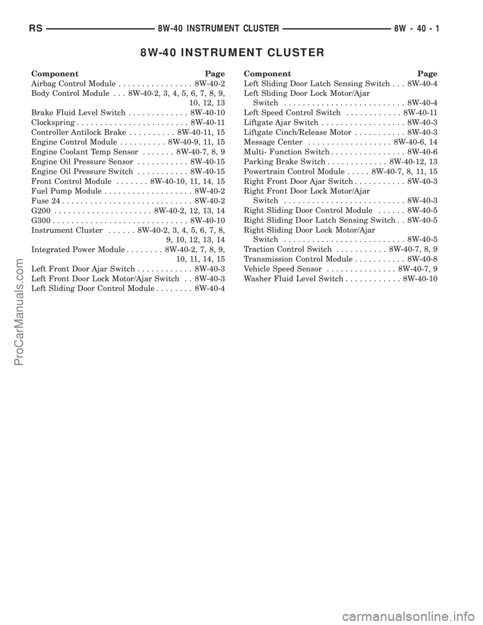
8W-40 INSTRUMENT CLUSTER
Component Page
Airbag Control Module................ 8W-40-2
Body Control Module . . . 8W-40-2, 3, 4, 5, 6, 7, 8, 9,
10, 12, 13
Brake Fluid Level Switch............. 8W-40-10
Clockspring........................ 8W-40-11
Controller Antilock Brake.......... 8W-40-11, 15
Engine Control Module.......... 8W-40-9, 11, 15
Engine Coolant Temp Sensor....... 8W-40-7, 8, 9
Engine Oil Pressure Sensor........... 8W-40-15
Engine Oil Pressure Switch........... 8W-40-15
Front Control Module....... 8W-40-10, 11, 14, 15
Fuel Pump Module................... 8W-40-2
Fuse 24............................ 8W-40-2
G200..................... 8W-40-2, 12, 13, 14
G300............................. 8W-40-10
Instrument Cluster...... 8W-40-2, 3, 4, 5, 6, 7, 8,
9, 10, 12, 13, 14
Integrated Power Module........ 8W-40-2, 7, 8, 9,
10, 11, 14, 15
Left Front Door Ajar Switch............ 8W-40-3
Left Front Door Lock Motor/Ajar Switch . . 8W-40-3
Left Sliding Door Control Module........ 8W-40-4Component Page
Left Sliding Door Latch Sensing Switch . . . 8W-40-4
Left Sliding Door Lock Motor/Ajar
Switch.......................... 8W-40-4
Left Speed Control Switch............ 8W-40-11
Liftgate Ajar Switch.................. 8W-40-3
Liftgate Cinch/Release Motor........... 8W-40-3
Message Center.................. 8W-40-6, 14
Multi- Function Switch................ 8W-40-6
Parking Brake Switch............. 8W-40-12, 13
Powertrain Control Module..... 8W-40-7, 8, 11, 15
Right Front Door Ajar Switch........... 8W-40-3
Right Front Door Lock Motor/Ajar
Switch.......................... 8W-40-3
Right Sliding Door Control Module...... 8W-40-5
Right Sliding Door Latch Sensing Switch . . 8W-40-5
Right Sliding Door Lock Motor/Ajar
Switch.......................... 8W-40-5
Traction Control Switch........... 8W-40-7, 8, 9
Transmission Control Module........... 8W-40-8
Vehicle Speed Sensor............... 8W-40-7, 9
Washer Fluid Level Switch............ 8W-40-10
RS8W-40 INSTRUMENT CLUSTER8W-40-1
ProCarManuals.com
Page 1188 of 2177
(3) Remove torque converter or clutch housing
cover and inspect rear of block for evidence of oil.
Use a black light to check for the oil leak. If a leak is
present in this area, remove transmission for further
inspection.
(a) Circular spray pattern generally indicates
seal leakage or crankshaft damage.
(b) Where leakage tends to run straight down,
possible causes are a porous block, oil gallery cup
plug, bedplate to cylinder block mating surfaces
and seal bore. See proper repair procedures for
these items.
(4) If no leaks are detected, pressurize the crank-
case as previously described.
CAUTION: Do not exceed 20.6 kPa (3 psi).
(5) If the leak is not detected, very slowly turn the
crankshaft and watch for leakage. If a leak is
detected between the crankshaft and seal while
slowly turning the crankshaft, it is possible the
crankshaft seal surface is damaged. The seal area on
the crankshaft could have minor nicks or scratches
that can be polished out with emery cloth.
CAUTION: Use extreme caution when crankshaft
polishing is necessary to remove minor nicks and
scratches. The crankshaft seal flange is especially
machined to complement the function of the rear oil
seal.
(6) For bubbles that remain steady with shaft
rotation, no further inspection can be done until dis-
assembled.
(7) After the oil leak root cause and appropriate
corrective action have been identified, replace compo-
nent(s) as necessary.
DIAGNOSIS AND TESTING - CYLINDER
COMPRESSION PRESSURE TEST
The results of a cylinder compression pressure test
can be utilized to diagnose several engine malfunc-
tions.
Ensure the battery is completely charged and the
engine starter motor is in good operating condition.
Otherwise the indicated compression pressures may
not be valid for diagnosis purposes.
(1) Check engine oil level and add oil if necessary.
(2) Drive the vehicle until engine reaches normal
operating temperature. Select a route free from traf-
fic and other forms of congestion, observe all traffic
laws, and accelerate through the gears several times
briskly.
(3) Remove all spark plugs from engine. As spark
plugs are being removed, check electrodes for abnor-
mal firing indicators fouled, hot, oily, etc. Record cyl-
inder number of spark plug for future reference.(4) Remove the Auto Shutdown (ASD) relay from
the PDC.
(5) Be sure throttle blade is fully open during the
compression check.
(6) Insert compression gauge adaptor Special Tool
8116 or the equivalent, into the #1 spark plug hole in
cylinder head. Connect the 0±500 psi (Blue) pressure
transducer (Special Tool CH7059) with cable adap-
tors to the DRBIIIt. For Special Tool identification,
(Refer to 9 - ENGINE - SPECIAL TOOLS).
(7) Crank engine until maximum pressure is
reached on gauge. Record this pressure as #1 cylin-
der pressure.
(8) Repeat the previous step for all remaining cyl-
inders.
(9) Compression should not be less than 689 kPa
(100 psi) and not vary more than 25 percent from cyl-
inder to cylinder.
(10) If one or more cylinders have abnormally low
compression pressures, repeat the compression test.
(11) If the same cylinder or cylinders repeat an
abnormally low reading on the second compression
test, it could indicate the existence of a problem in
the cylinder in question.The recommended com-
pression pressures are to be used only as a
guide to diagnosing engine problems. An engine
should not be disassembled to determine the
cause of low compression unless some malfunc-
tion is present.
DIAGNOSIS AND TESTING - CYLINDER
COMBUSTION PRESSURE LEAKAGE TEST
The combustion pressure leakage test provides an
accurate means for determining engine condition.
Combustion pressure leakage testing will detect:
²Exhaust and intake valve leaks (improper seat-
ing).
²Leaks between adjacent cylinders or into water
jacket.
²Any causes for combustion/compression pressure
loss.
WARNING: DO NOT REMOVE THE PRESSURE CAP
WITH THE SYSTEM HOT AND UNDER PRESSURE
BECAUSE SERIOUS BURNS FROM COOLANT CAN
OCCUR.
Check the coolant level and fill as required. DO
NOT install the pressure cap.
Start and operate the engine until it attains nor-
mal operating temperature, then turn the engine
OFF.
Clean spark plug recesses with compressed air.
Remove the spark plugs.
Remove the oil filler cap.
Remove the air cleaner.
RSENGINE 2.4L9-9
ENGINE 2.4L (Continued)
ProCarManuals.com
Page 1190 of 2177
CAUTION: Squirt approximately one teaspoon of oil
into the cylinders, rotate engine to lubricate the cyl-
inder walls to prevent damage on restart.
(8) Install new spark plugs.
(9) Drain engine oil and remove oil filter.
(10) Install a new oil filter.
(11) Fill engine with specified amount of approved
oil.
(12) Connect negative battery cable.
(13) Start engine and check for any leaks.
STANDARD PROCEDURE - FORM-IN-PLACE
GASKETS AND SEALERS
There are numerous places where form-in-place
gaskets are used on the engine. Care must be taken
when applying form-in-place gaskets to assure
obtaining the desired results.Do not use form-in-
place gasket material unless specified.Bead size,
continuity, and location are of great importance. Too
thin a bead can result in leakage while too much can
result in spill-over which can break off and obstruct
fluid feed lines. A continuous bead of the proper
width is essential to obtain a leak-free gasket.
There are numerous types of form-in-place gasket
materials that are used in the engine area. Mopart
Engine RTV GEN II, MopartATF-RTV, and Mopart
Gasket Maker gasket materials, each have different
properties and can not be used in place of the other.
MOPARtENGINE RTV GEN IIis used to seal
components exposed to engine oil. This material is a
specially designed black silicone rubber RTV that
retains adhesion and sealing properties when
exposed to engine oil. Moisture in the air causes the
material to cure. This material is available in three
ounce tubes and has a shelf life of one year. After one
year this material will not properly cure. Always
inspect the package for the expiration date before
use.
MOPARtATF RTVis a specifically designed
black silicone rubber RTV that retains adhesion and
sealing properties to seal components exposed to
automatic transmission fluid, engine coolants, and
moisture. This material is available in three ounce
tubes and has a shelf life of one year. After one year
this material will not properly cure. Always inspect
the package for the expiration date before use.
MOPARtGASKET MAKERis an anaerobic type
gasket material. The material cures in the absence of
air when squeezed between two metallic surfaces. It
will not cure if left in the uncovered tube. The
anaerobic material is for use between two machined
surfaces. Do not use on flexible metal flanges.
MOPARtBED PLATE SEALANTis a unique
(green-in-color) anaerobic type gasket material that
is specially made to seal the area between the bed-plate and cylinder block without disturbing the bear-
ing clearance or alignment of these components. The
material cures slowly in the absence of air when
torqued between two metallic surfaces, and will rap-
idly cure when heat is applied.
MOPARtGASKET SEALANTis a slow drying,
permanently soft sealer. This material is recom-
mended for sealing threaded fittings and gaskets
against leakage of oil and coolant. Can be used on
threaded and machined parts under all tempera-
tures. This material is used on engines with multi-
layer steel (MLS) cylinder head gaskets. This
material also will prevent corrosion. MopartGasket
Sealant is available in a 13 oz. aerosol can or 4oz./16
oz. can w/applicator.
SEALER APPLICATION
MopartGasket Maker material should be applied
sparingly 1 mm (0.040 in.) diameter or less of sealant
to one gasket surface. Be certain the material sur-
rounds each mounting hole. Excess material can eas-
ily be wiped off. Components should be torqued in
place within 15 minutes. The use of a locating dowel
is recommended during assembly to prevent smear-
ing material off the location.
MopartEngine RTV GEN II or ATF RTV gasket
material should be applied in a continuous bead
approximately 3 mm (0.120 in.) in diameter. All
mounting holes must be circled. For corner sealing, a
3.17 or 6.35 mm (1/8 or 1/4 in.) drop is placed in the
center of the gasket contact area. Uncured sealant
may be removed with a shop towel. Components
should be torqued in place while the sealant is still
wet to the touch (within 10 minutes). The usage of a
locating dowel is recommended during assembly to
prevent smearing material off the location.
MopartGasket Sealant in an aerosol can should be
applied using a thin, even coat sprayed completely
over both surfaces to be joined, and both sides of a
gasket. Then proceed with assembly. Material in a
can w/applicator can be brushed on evenly over the
sealing surfaces. Material in an aerosol can should be
used on engines with multi-layer steel gaskets.
STANDARD PROCEDURE - ENGINE GASKET
SURFACE PREPARATION
To ensure engine gasket sealing, proper surface
preparation must be performed, especially with the
use of aluminum engine components and multi-layer
steel cylinder head gaskets.
Neveruse the following to clean gasket surfaces:
²Metal scraper
²Abrasive pad or paper to clean cylinder block
and head
²High speed power tool with an abrasive pad or a
wire brush (Fig. 3)
RSENGINE 2.4L9-11
ENGINE 2.4L (Continued)
ProCarManuals.com
Page 1192 of 2177
REMOVAL - ENGINE ASSEMBLY
(1) Perform fuel pressure release procedure (Refer
to 14 - FUEL SYSTEM/FUEL DELIVERY - STAN-
DARD PROCEDURE)
(2) Disconnect battery negative cable.
(3) Remove air cleaner housing and inlet tube.
(4) Disconnect the fuel line from fuel rail. (Refer to
14 - FUEL SYSTEM/FUEL DELIVERY/FUEL LINES
- STANDARD PROCEDURE)
(5) Disconnect all vacuum hoses.
(6) Drain cooling system. (Refer to 7 - COOLING -
STANDARD PROCEDURE)
(7) Remove radiator fans. (Refer to 7 - COOLING/
ENGINE/RADIATOR FAN - REMOVAL)
(8) Remove radiator upper and lower hoses.
NOTE: When the transaxle cooler lines are removed
from the rolled-groove type fittings at the transaxle,
damage to the inner wall of the hose will occur. To
prevent prevent potential leakage, the cooler hoses
must be cut off flush at the transaxle fitting, and a
service cooler hose splice kit must be installed
upon reassembly.(9) Using a blade or suitable hose cutter, cut trans-
axle oil cooler lines off flush with fittings. Plug cooler
lines and fittings to prevent debris from entering
transaxle or cooler circuit. A service splice kit will be
installed upon reassembly.
(10) Disconnect transmission shift linkage and
electrical connectors.
(11) Disconnect throttle body linkage.
(12) Disconnect engine wiring harness.
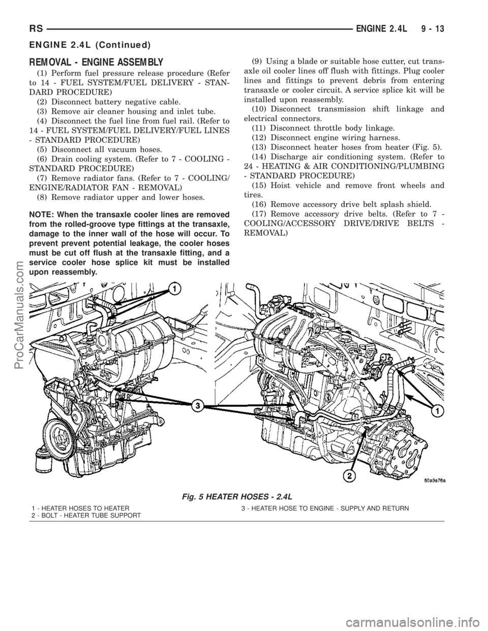
(13) Disconnect heater hoses from heater (Fig. 5).
(14) Discharge air conditioning system. (Refer to
24 - HEATING & AIR CONDITIONING/PLUMBING
- STANDARD PROCEDURE)
(15) Hoist vehicle and remove front wheels and
tires.
(16) Remove accessory drive belt splash shield.
(17) Remove accessory drive belts. (Refer to 7 -
COOLING/ACCESSORY DRIVE/DRIVE BELTS -
REMOVAL)
Fig. 5 HEATER HOSES - 2.4L
1 - HEATER HOSES TO HEATER 3 - HEATER HOSE TO ENGINE - SUPPLY AND RETURN
2 - BOLT - HEATER TUBE SUPPORT
RSENGINE 2.4L9-13
ENGINE 2.4L (Continued)
ProCarManuals.com
Page 1193 of 2177
(18) Remove axle shafts. (Refer to 3 - DIFFEREN-
TIAL & DRIVELINE/HALF SHAFT - REMOVAL)
(19) Drain engine oil and remove oil filter. (Refer
to 9 - ENGINE/LUBRICATION/OIL - STANDARD
PROCEDURE)
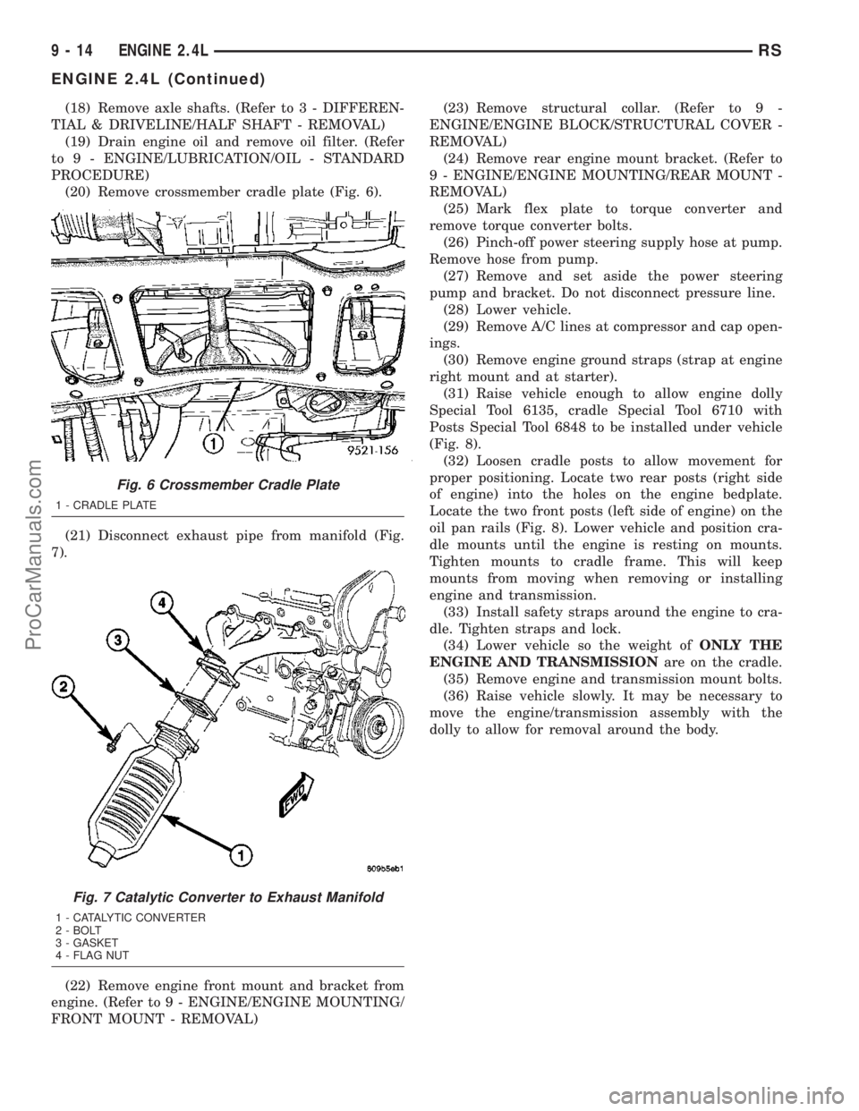
(20) Remove crossmember cradle plate (Fig. 6).
(21) Disconnect exhaust pipe from manifold (Fig.
7).
(22) Remove engine front mount and bracket from
engine. (Refer to 9 - ENGINE/ENGINE MOUNTING/
FRONT MOUNT - REMOVAL)(23) Remove structural collar. (Refer to 9 -
ENGINE/ENGINE BLOCK/STRUCTURAL COVER -
REMOVAL)
(24) Remove rear engine mount bracket. (Refer to
9 - ENGINE/ENGINE MOUNTING/REAR MOUNT -
REMOVAL)
(25) Mark flex plate to torque converter and
remove torque converter bolts.
(26) Pinch-off power steering supply hose at pump.
Remove hose from pump.
(27) Remove and set aside the power steering
pump and bracket. Do not disconnect pressure line.
(28) Lower vehicle.
(29) Remove A/C lines at compressor and cap open-
ings.
(30) Remove engine ground straps (strap at engine
right mount and at starter).
(31) Raise vehicle enough to allow engine dolly
Special Tool 6135, cradle Special Tool 6710 with
Posts Special Tool 6848 to be installed under vehicle
(Fig. 8).
(32) Loosen cradle posts to allow movement for
proper positioning. Locate two rear posts (right side
of engine) into the holes on the engine bedplate.
Locate the two front posts (left side of engine) on the
oil pan rails (Fig. 8). Lower vehicle and position cra-
dle mounts until the engine is resting on mounts.
Tighten mounts to cradle frame. This will keep
mounts from moving when removing or installing
engine and transmission.
(33) Install safety straps around the engine to cra-
dle. Tighten straps and lock.
(34) Lower vehicle so the weight ofONLY THE
ENGINE AND TRANSMISSIONare on the cradle.
(35) Remove engine and transmission mount bolts.
(36) Raise vehicle slowly. It may be necessary to
move the engine/transmission assembly with the
dolly to allow for removal around the body.
Fig. 6 Crossmember Cradle Plate
1 - CRADLE PLATE
Fig. 7 Catalytic Converter to Exhaust Manifold
1 - CATALYTIC CONVERTER
2 - BOLT
3 - GASKET
4 - FLAG NUT
9 - 14 ENGINE 2.4LRS
ENGINE 2.4L (Continued)
ProCarManuals.com
Page 1195 of 2177
INSTALLATION - ENGINE ASSEMBLY
(1) Position engine and transmission assembly
under vehicle and slowly lower the vehicle over the
engine and transmission.
(2) Align engine and transmission mounts to
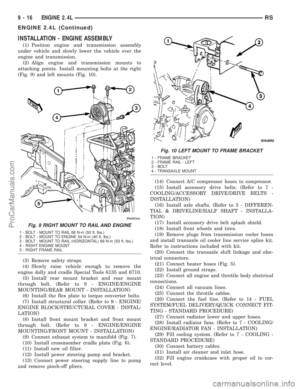
attaching points. Install mounting bolts at the right
(Fig. 9) and left mounts (Fig. 10).
(3) Remove safety straps.
(4) Slowly raise vehicle enough to remove the
engine dolly and cradle Special Tools 6135 and 6710.
(5) Install rear mount bracket and rear mount
through bolt. (Refer to 9 - ENGINE/ENGINE
MOUNTING/REAR MOUNT - INSTALLATION)
(6) Install the flex plate to torque converter bolts.
(7) Install structural collar. (Refer to 9 - ENGINE/
ENGINE BLOCK/STRUCTURAL COVER - INSTAL-
LATION)
(8) Install front mount bracket and front mount
through bolt. (Refer to 9 - ENGINE/ENGINE
MOUNTING/FRONT MOUNT - INSTALLATION)
(9) Connect exhaust system to manifold (Fig. 7).
(10) Install crossmember cradle plate (Fig. 6).
(11) Install new oil filter.
(12) Install power steering pump and bracket.
(13) Connect power steering supply line to pump
and remove pinch-off pliers.(14) Connect A/C compressor hoses to compressor.
(15) Install accessory drive belts. (Refer to 7 -
COOLING/ACCESSORY DRIVE/DRIVE BELTS -
INSTALLATION)
(16) Install axle shafts. (Refer to 3 - DIFFEREN-
TIAL & DRIVELINE/HALF SHAFT - INSTALLA-
TION)
(17) Install accessory drive belt splash shield.
(18) Install front wheels and tires.
(19) Remove plugs from transmission cooler hoses
and install transaxle oil cooler line service splice kit.
Refer to instructions included with kit.
(20) Connect the transaxle shift linkage and elec-
trical connectors.
(21) Connect heater hoses (Fig. 5).
(22) Install ground straps.
(23) Connect all engine and throttle body electrical
connections.
(24) Connect all vacuum lines.
(25) Connect the throttle cables.
(26) Connect the fuel line. (Refer to 14 - FUEL
SYSTEM/FUEL DELIVERY/QUICK CONNECT FIT-
TING - STANDARD PROCEDURE)
(27) Connect radiator lower and upper hoses.
(28) Install radiator fans. (Refer to 7 - COOLING/
ENGINE/RADIATOR FAN - INSTALLATION)
(29) Fill cooling system. (Refer to 7 - COOLING -
STANDARD PROCEDURE)
(30) Connect battery cables.
(31) Install air cleaner and inlet hose.
(32) Fill engine crankcase with proper oil to cor-
rect level.
Fig. 9 RIGHT MOUNT TO RAIL AND ENGINE
1 - BOLT - MOUNT TO RAIL 68 N´m (50 ft. lbs.)
2 - BOLT - MOUNT TO ENGINE 54 N´m (40 ft. lbs.)
3 - BOLT - MOUNT TO RAIL (HORIZONTAL) 68 N´m (50 ft. lbs.)
4 - RIGHT ENGINE MOUNT
5 - RIGHT FRAME RAIL
Fig. 10 LEFT MOUNT TO FRAME BRACKET
1 - FRAME BRACKET
2 - FRAME RAIL - LEFT
3 - BOLT
4 - TRANSAXLE MOUNT
9 - 16 ENGINE 2.4LRS
ENGINE 2.4L (Continued)
ProCarManuals.com