ignition DODGE TRUCK 1993 Service Repair Manual
[x] Cancel search | Manufacturer: DODGE, Model Year: 1993, Model line: TRUCK, Model: DODGE TRUCK 1993Pages: 1502, PDF Size: 80.97 MB
Page 873 of 1502
14-54 FUEL SYSTEM
• is good, replace the PCM. If terminal/pin-4 has a
short circuit to 12 volts +, correct this condition be
fore replacing the PCM.
CRANKSHAFT POSITION SENSOR TEST
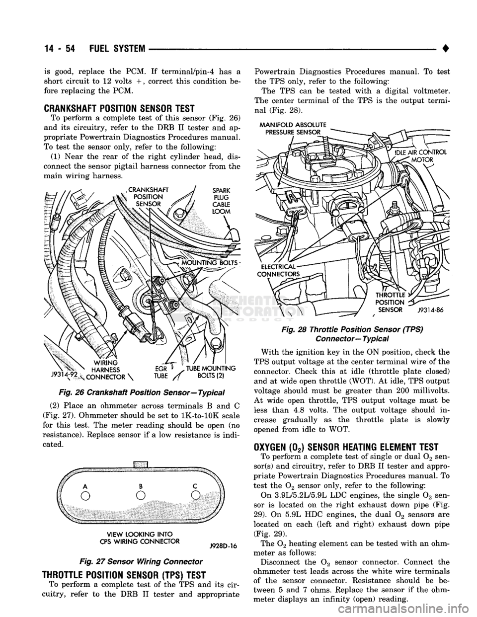
To perform a complete test of this sensor (Fig. 26)
and its circuitry, refer to the DRB II tester and ap
propriate Powertrain Diagnostics Procedures manual.
To test the sensor only, refer to the following: (1) Near the rear of the right cylinder head, dis
connect the sensor pigtail harness connector from the
main wiring harness.
Fig.
26 Crankshaft Position
Sensor—
Typical
(2) Place an ohmmeter across terminals B and C
(Fig. 27). Ohmmeter should be set to lK-to-lOK scale
for this test. The meter reading should be open (no
resistance). Replace sensor if a low resistance is indi
cated.
VIEW
LOOKING
INTO
CPS
WIRING
CONNECTOR
Fig.
27
Sensor
Wiring
Connector
THROTTLE POSITION SENSOR (TPS) TEST
To perform a complete test of the TPS and its cir
cuitry, refer to the DRB II tester and appropriate Powertrain Diagnostics Procedures manual. To test
the TPS only, refer to the following:
The TPS can be tested with a digital voltmeter.
The center terminal of the TPS is the output termi nal (Fig. 28).
AAANIFOLD
ABSOLUTE
Fig.
28
Throttle
Position
Sensor
(TPS)
Connector—
Typical
With the ignition key in the ON position, check the
TPS output voltage at the center terminal wire of the connector. Check this at idle (throttle plate closed) and at wide open throttle (WOT). At idle, TPS output
voltage should must be greater than 200 millivolts.
At wide open throttle, TPS output voltage must be
less than 4.8 volts. The output voltage should in
crease gradually as the throttle plate is slowly
opened from idle to WOT.
OXYGEN
(02)
SENSOR HEATING ELEMENT TEST
To perform a complete test of single or dual 02 sen-
sor(s) and circuitry, refer to DRB II tester and appro
priate Powertrain Diagnostics Procedures manual. To
test the 02 sensor only, refer to the following:
On 3.9L/5.2L/5.9L LDC engines, the single 02 sen
sor is located on the right exhaust down pipe (Fig.
29).
On 5.9L HDC engines, the dual 02 sensors are
located on each (left and right) exhaust down pipe (Fig. 29).
The 02 heating element can be tested with an ohm
meter as follows: Disconnect the 02 sensor connector. Connect the
ohmmeter test leads across the white wire terminals
of the sensor connector. Resistance should be be
tween 5 and 7 ohms. Replace the sensor if the ohm meter displays an infinity (open) reading.
Page 874 of 1502
•
FUEL
SYSTEM
14 - 55
Fig.
30
Dual
Oxygen
Sensors—5.9L
HDC
Engine
IDLE
AIR
CONTROL
(IAC)
MOTOR
TEST
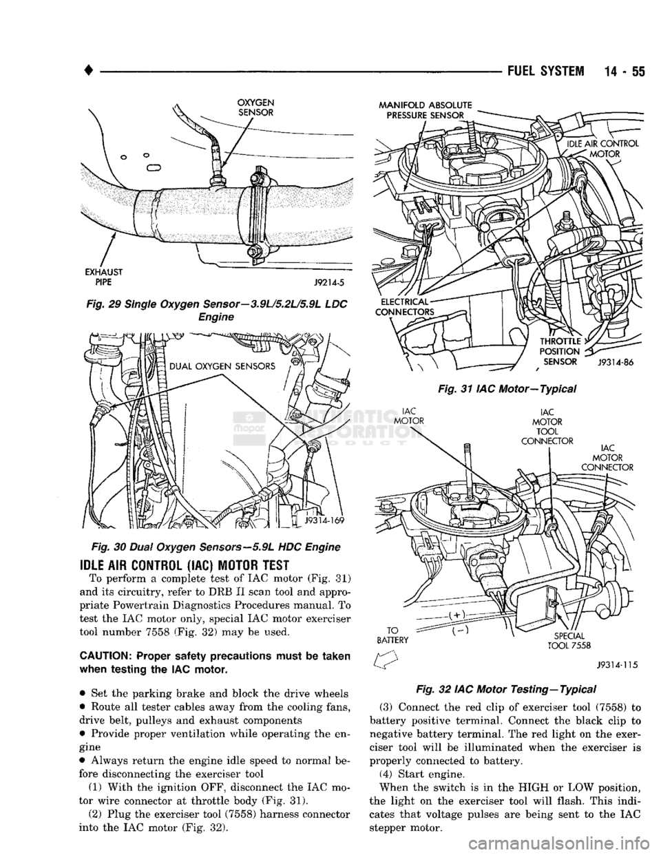
To perform a complete test of IAC motor (Fig. 81)
and its circuitry, refer to DRB II scan tool and appro
priate Powertrain Diagnostics Procedures manual. To
test the IAC motor only, special IAC motor exerciser tool number 7558 (Fig. 32) may be used.
CAUTION:
Proper safety precautions must be
taken
when
testing
the IAC
motor,
• Set the parking brake and block the drive wheels
• Route all tester cables away from the cooling fans,
drive belt, pulleys and exhaust components
• Provide proper ventilation while operating the en
gine
• Always return the engine idle speed to normal be
fore disconnecting the exerciser tool
(1) With the ignition OFF, disconnect the IAC mo
tor wire connector at throttle body (Fig. 31).
(2) Plug the exerciser tool (7558) harness connector
into the IAC motor (Fig. 32).
MANIFOLD
ABSOLUTE
Fig.
31 IAC Motor—Typical
Fig.
32 IAC Motor
Testing—
Typical
(3) Connect the red clip of exerciser tool (7558) to
battery positive terminal. Connect the black clip to
negative battery terminal. The red light on the exer
ciser tool will be illuminated when the exerciser is
properly connected to battery. (4) Start engine.
When the switch is in the HIGH or LOW position,
the light on the exerciser tool will flash. This indi cates that voltage pulses are being sent to the IAC
stepper motor.
Page 875 of 1502
14
- 56
FUEL
SYSTEM
• (5) Move the switch to the HIGH position. The en
gine speed should increase. Move the switch to the
LOW position. The engine speed should decrease.
(a) If the engine speed changes while using the
exerciser tool, the IAC motor is functioning prop
erly. Disconnect the exerciser tool and connect the
IAC stepper motor wire connector to the stepper motor.
(b) If the engine speed does not change, turn the
ignition OFF and proceed to step (6). Do not discon
nect exerciser from the IAC stepper motor.
(6) Remove the IAC stepper motor from the throt
tle body.
CAUTION:
When checking IAC motor operation with
the motor removed from
the
throttle
body,
do not
extend
the
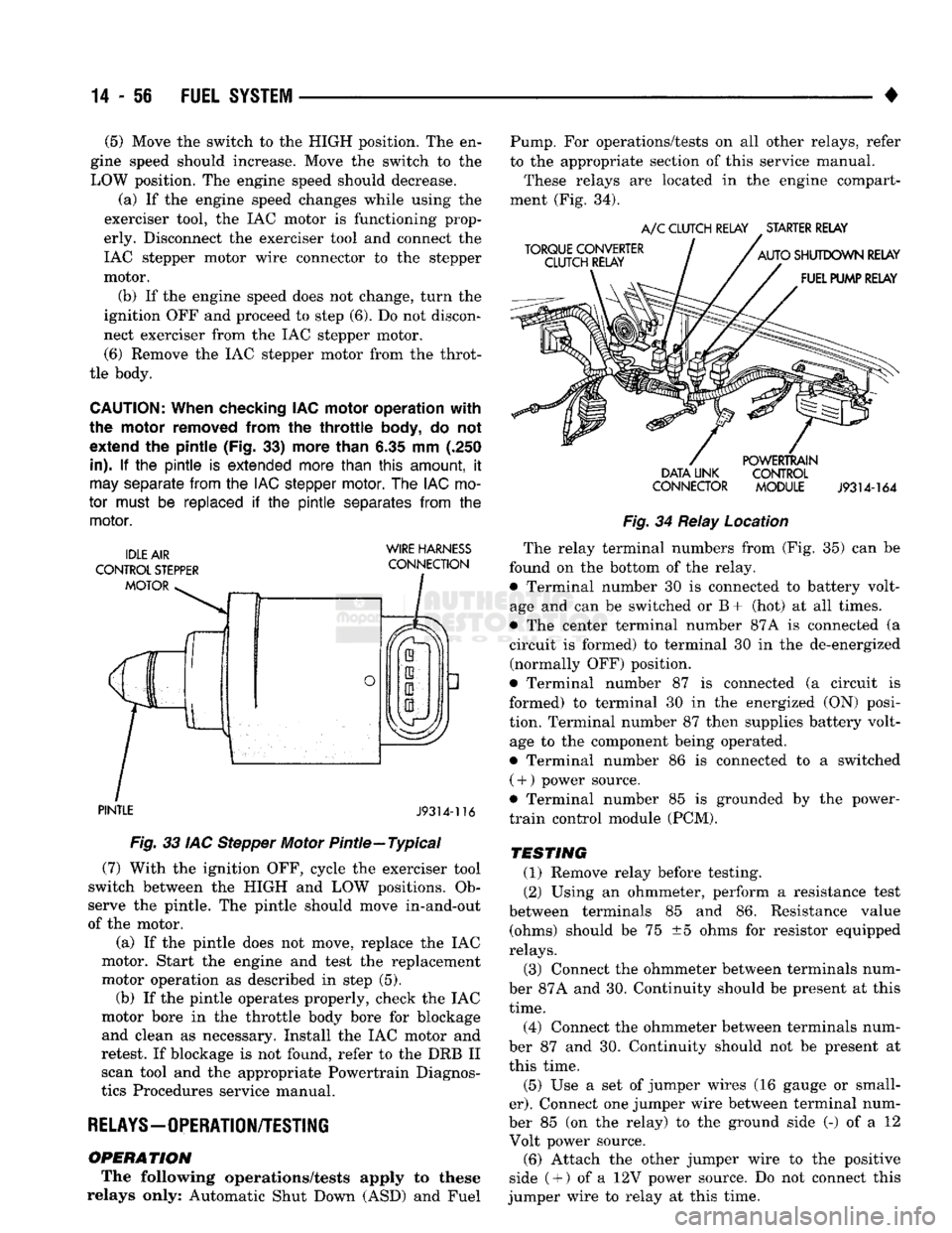
pintle (Fig.
33)
more than
6.35 mm (.250
in).
If the pintle is
extended more than
this
amount,
it
may
separate
from
the
IAC stepper
motor.
The
IAC
mo
tor
must
be
replaced
if the pintle
separates
from
the
motor.
WIRE HARNESS
PINTLE
J9314-116
Fig.
33 IAC Stepper Motor Pintle—Typical (7) With the ignition OFF, cycle the exerciser tool
switch between the HIGH and LOW positions. Ob
serve the pintle. The pintle should move in-and-out
of the motor.
(a) If the pintle does not move, replace the IAC
motor. Start the engine and test the replacement
motor operation as described in step (5). (b) If the pintle operates properly, check the IAC
motor bore in the throttle body bore for blockage and clean as necessary. Install the IAC motor and
retest. If blockage is not found, refer to the DRB II scan tool and the appropriate Powertrain Diagnos
tics Procedures service manual.
RELAYS—OPERATION/TESTING
OPERATION
The following operations/tests apply to these
relays only: Automatic Shut Down (ASD) and Fuel Pump. For operations/tests on all other relays, refer
to the appropriate section of this service manual.
These relays are located in the engine compart
ment (Fig. 34).
DATA LINK CONTROL
CONNECTOR MODULE
J9314-164
Fig.
34 Relay Location The relay terminal numbers from (Fig. 35) can be
found on the bottom of the relay. • Terminal number 30 is connected to battery volt
age and can be switched or B+ (hot) at all times.
• The center terminal number 87A is connected (a
circuit is formed) to terminal 30 in the de-energized (normally OFF) position.
• Terminal number 87 is connected (a circuit is
formed) to terminal 30 in the energized (ON) posi
tion. Terminal number 87 then supplies battery volt age to the component being operated.
• Terminal number 86 is connected to a switched ( +
)
power source.
• Terminal number 85 is grounded by the power-
train control module (PCM).
TESTING
(1) Remove relay before testing. (2) Using an ohmmeter, perform a resistance test
between terminals 85 and 86. Resistance value (ohms) should be 75 ±5 ohms for resistor equipped
relays.
(3) Connect the ohmmeter between terminals num
ber 87A and 30. Continuity should be present at this
time.
(4) Connect the ohmmeter between terminals num
ber 87 and 30. Continuity should not be present at
this time.
(5) Use a set of jumper wires (16 gauge or small
er).
Connect one jumper wire between terminal num
ber 85 (on the relay) to the ground side (-) of a 12 Volt power source. (6) Attach the other jumper wire to the positive
side ( +
)
of a 12V power source. Do not connect this
jumper wire to relay at this time.
Page 877 of 1502
14 - 58
FUEL
SYSTEM
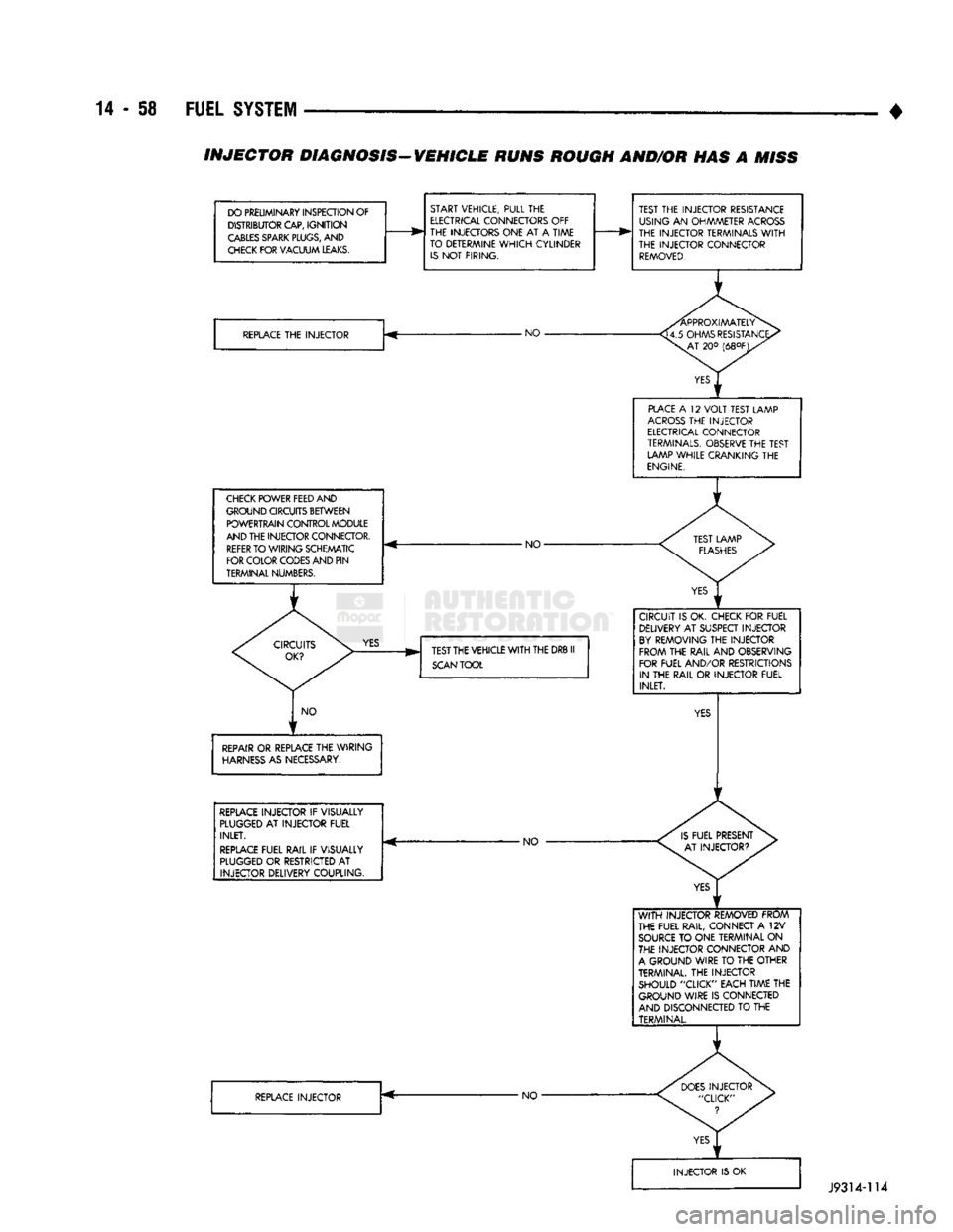
• INJECTOR DIAGNOSIS-VEHICLE RUNS ROUGH AND/OR HAS A
MISS
DO PRELIMINARY INSPECTION OF DISTRIBUTOR CAP,
IGNITION
CABLES
SPARK
PLUGS,
AND
CHECK
FOR VACUUM
LEAKS.
START VEHICLE, PULL THE
ELECTRICAL
CONNECTORS OFF
THE INJECTORS ONE AT A TIME
TO DETERMINE
WHICH
CYLINDER
IS
NOT FIRING.
REPLACE
THE INJECTOR -NO •
CHECK
POWER FEED AND
GROUND CIRCUITS BETWEEN POWERTRAIN CONTROL MODULE
AND THE INJECTOR CONNECTOR.
REFER
TO WIRING SCHEMATIC
FOR COLOR CODES AND PIN
TERMINAL NUMBERS. - NO-
YES
TEST THE VEHICLE
WITH
THE DRB II
SCAN
TOOL
NO
REPAIR
OR REPLACE THE WIRING
HARNESS
AS NECESSARY.
REPLACE
INJECTOR IF VISUALLY
PLUGGED
AT INJECTOR FUEL INLET.
REPLACE
FUEL RAIL IF VISUALLY
PLUGGED
OR RESTRICTED AT INJECTOR DELIVERY COUPLING. -NO
REPLACE
INJECTOR •NO-TEST THE INJECTOR RESISTANCE
USING AN OHMMETER
ACROSS
THE INJECTOR TERMINALS
WITH
THE INJECTOR CONNECTOR
REMOVED.
PLACE
A 12
VOLT
TEST LAMP
ACROSS
THE INJECTOR
ELECTRICAL
CONNECTOR
TERMINALS.
OBSERVE THE TEST LAMP WHILE CRANKING THE
ENGINE.
CIRCUIT IS OK. CHECK FOR FUEL DELIVERY AT SUSPECT INJECTOR
BY
REMOVING THE INJECTOR FROM THE RAIL AND OBSERVING
FOR FUEL AND/OR RESTRICTIONS IN THE RAIL OR INJECTOR FUEL INLET.
WITH
INJECTOR REMOVED FROM
THE FUEL RAIL, CONNECT A 12V
SOURCE
TO ONE TERMINAL ON
THE INJECTOR CONNECTOR AND
A
GROUND WIRE TO THE OTHER
TERMINAL. THE INJECTOR SHOULD "CLICK" EACH TIME THE GROUND WIRE IS CONNECTED
AND DISCONNECTED TO THE TERMINAL.
J9314-114
Page 878 of 1502
•
FUEL SYSTEM
14 - 59
fill
DHADn
HIAf5MflCTipQ
/f|Rn
The powertrain control module (PCM) has been
programmed to monitor many different circuits of the
fuel injection system. If a problem is sensed in a monitored circuit often enough to indicate an actual
problem, a diagnostic trouble code (DTC) is stored.
The DTC will be stored in the PCM memory for eventual display to the service technician. If the
problem is repaired or ceases to exist, the PCM can cels the DTC after 51 engine starts.
Certain criteria must be met for a diagnostic trou
ble code (DTC) to be entered into PCM memory. The criteria may be a specific range of engine rpm, en
gine temperature and/or input voltage to the PCM.
It is possible that a DTC for a monitored circuit
may not be entered into memory even though a mal
function has occurred. This may happen because one
of the DTC criteria for the circuit has not been met. Example: assume that one of the criteria for the
MAP sensor circuit is that the engine must be oper ating between 750 and 2000 rpm to be monitored for
a DTC. If the MAP sensor output circuit shorts to
ground when the engine rpm is above 2400 rpm, a 0
volt input will be seen by the PCM. A DTC will not
be entered into memory because the condition does not occur within the specified rpm range.
A DTC indicates that the powertrain control mod
ule (PCM) has recognized an abnormal signal in a
circuit or the system. A DTC may indicate the result
of a failure, but never identify the failed component
directly.
There are several operating conditions that the
PCM does not monitor and set a DTC for. Refer to
the following Monitored Circuits and Non-Monitored Circuits in this section.
MONITORED
CIRCUITS
The powertrain control module (PCM) can detect
certain problems in the fuel injection system.
Open or Shorted Circuit - The PCM can deter
mine if sensor output (which is the input to PCM) is
within proper range. It also determines if the circuit is open or shorted.
Output Device Current Flow - The PCM senses
whether the output devices are hooked up.
If there is a problem with the circuit, the PCM
senses whether the circuit is open, shorted to ground
(-), or shorted to
(
+
)
voltage.
Oxygen Sensor - The PCM can determine if the
oxygen sensor is switching between rich and lean.
This is, once the system has entered Closed Loop. Re fer to Open Loop/Closed Loop Modes Of Operation in
the Component Description/System Operation section
for an explanation of Closed (or Open) Loop opera tion.
NON-MONITORED CIRCUITS
The PCM does not monitor the following circuits,
systems or conditions that could have malfunctions
that result in driveability problems. A diagnostic trouble code (DTC) may not be displayed for these
conditions.
Fuel Pressure: Fuel pressure is controlled by the
vacuum assisted fuel pressure regulator. The PCM
cannot detect a clogged fuel pump inlet filter, clogged
in-line fuel filter, or a pinched fuel supply or return
line.
However, these could result in a rich or lean
condition causing an oxygen sensor DTC to be stored in the PCM.
Secondary Ignition Circuit: The PCM cannot de
tect an inoperative ignition coil, fouled or worn spark
plugs,
ignition cross firing, or open circuited spark
plug cables.
Engine Timing: The PCM cannot detect an incor
rectly indexed timing chain, camshaft sprocket or crankshaft sprocket. The PCM also cannot detect an
incorrectly indexed distributor. However, these could
result in a rich or lean condition causing an oxygen
sensor DTC to be stored in the PCM.
Cylinder Compression: The PCM cannot detect
uneven, low, or high engine cylinder compression.
Exhaust System: The PCM cannot detect
a
plugged, restricted or leaking exhaust system.
Fuel Injector Malfunctions: The PCM cannot de
termine if the fuel injector is clogged, or the wrong injector is installed. However, these could result in a
rich or lean condition causing an oxygen sensor DTC
to be stored in the PCM.
Excessive Oil Consumption: Although the PCM
monitors exhaust stream oxygen content through ox
ygen sensor (closed loop), it cannot determine exces sive oil consumption.
Throttle Body Air Flow: The PCM cannot detect
a clogged or restricted air cleaner inlet or air filter
element.
Evaporative System: The PCM will not detect a
restricted, plugged or loaded EVAP canister. Vacuum Assist: Leaks or restrictions in the vac
uum circuits of vacuum assisted engine control sys
tem devices are not monitored by the PCM. However, a vacuum leak at the MAP sensor will be monitored
and a diagnostic trouble code (DTC) will be gener
ated by the PCM.
Powertrain Control Module (PCM) System
Ground: The PCM cannot determine a poor system
ground. However, a DTC may be generated as a re
sult of this condition.
Powertrain Control Module (PCM) Connector
Engagement: The PCM cannot determine spread or
damaged connector pins. However, a DTC may be generated as a result of this condition.
Page 879 of 1502
14 - SO
FUEL
SYSTEM
•
HIGH
AND LOW
LIMITS
The powertrain control module (PCM) compares in
put signal voltages from each input device. It will es
tablish high and low limits that are programmed into it for that device. If the input voltage is not
within specifications and other diagnostic trouble code (DTC) criteria are met, a DTC will be stored in
memory. Other DTC criteria might include engine
rpm limits or input voltages from other sensors or switches. The other inputs might have to be sensed
by the PCM when it senses a high or low input volt age from the control system device in question.
ACCESSING DIAGNOSTIC TROUBLE CODES A stored diagnostic trouble code (DTC) can be dis
played by cycling the ignition key On-Off-On-Off-On
within three seconds and observing the malfunction indicator lamp. This lamp was formerly referred to
as the check engine lamp. The lamp is located on the
instrument panel.
They can also be displayed through the use of the
Diagnostic Readout Box II (DRB II scan tool). The
DRB II connects to the data link connector in the ve
hicle (Fig. 37). For operation of the DRB II, refer to
the appropriate Powertrain Diagnostic Procedures service manual.
TORQUE CONVERTER
CLUTCH RELAY
A/C
CLUTCH RELAY
.
STARTER RELAY
AUTO
SHUTDOWN RELAY FUEL PUMP RELAY POWERTRAIN
DATA LINK CONTROL
CONNECTOR MODULE
J9314-164
Fig.
37
Data
Link
Connector
Location—Typical
EXAMPLES
• If the lamp flashes 4 times, pauses and flashes 1
more time, a diagnostic trouble code (DTC) number
41 is indicated.
• If the lamp flashes 4 times, pauses and flashes 6
more times, a diagnostic trouble code (DTC) number
46 is indicated. Refer to the Diagnostic Trouble Code (DTC) charts
for DTC identification. If the problem is repaired or ceases to exist, the
powertrain control module (PCM) cancels the DTC after 51 engine starts.
Diagnostic trouble codes indicate the results of a
failure, but never identify the failed component di
rectly. The circuits of the data link connector are shown
in (Fig. 38).
J9214-20
D-1
GROUND
D-2 Im/c
D-3
SCI
TRANS
D-4
SCI
RECEIVE
D-5
IGNITION
D-6
NOT
USED
Fig.
38
Data
Link
Connector
Schematic
ERASING TROUBLE CODES The DRB II scan tool must be used to erase a di
agnostic trouble code (DTC). Refer to the appropriate
Powertrain Diagnostic Procedures service manual for operation of the DRB II scan tool.
DRB
II
SCAN
TOOL
For operation of the DRB II scan tool, refer to the
appropriate Powertrain Diagnostic Procedures ser
vice manual.
DIAGNOSTIC TROUBLE CODE
(DTC) On the following pages, a list of diagnostic trouble
codes is provided for all gas powered engines. A DTC indicates that the powertrain control module (PCM)
has recognized an abnormal signal in a circuit or the system. A DTC may indicate the result of a failure,
but never identify the failed component directly.
Page 883 of 1502
MULTI-PORT
FUEL
INJECTION
(MPI)-COMPONENT
REMOVAL/INSTALLATION
—EXCEPT DIESEL
INDEX
page
Accelerator Pedal
and Throttle
Cable
. 64
Air Conditioning (A/C) Clutch Relay
64
Air
Filter/Filter
Housing
64
Automatic Shut Down (ASD) Relay
. 64
Brake
Switch
64
Camshaft
Position
Sensor
..................
64
Charge
Air
Temperature
Sensor
64
Crankshaft Position
Sensor
64
Engine
Coolant Temperature
Sensor
65
EVAP
Canister Purge Solenoid
65
Fuel
Filter
65
Fuel Filter/Fuel Pressure Regulator—5.9L Engine
. 65
Fuel Injector(S)
67
Fuel Pressure Regulator
67
Fuel Pump Module
68
Fuel Pump Relay
68
ACCELERATOR
PEDAL
AND THROTTLE
CABLE
Refer
to
the
Accelerator Pedal
and
Throttle Cable
section
of
this group
for
removal/installation proce
dures.
AIR
CONDITIONING (A/C) CLUTCH RELAY The A/C clutch relay
is
located
in
the
engine com
partment (Fig.
1).
A/C CLUTCH RELAY STARTER RELAY
DATA LINK CONTROL
CONNECTOR MODULE
J9314-164
Fig.
1 Relay Location
AIR
FILTER/FILTER
HOUSING
Refer
to
Air Filter/Filter Housing—Gas Engines
in
Group
25,
Emission Control System
for
removal/in
stallation procedures.
AUTOMATIC SHUT DOWN (ASD) RELAY The ASD relay
is
located
in
the
engine compart
ment (Fig.
1).
page
Fuel Rail
69
Fuel System Pressure Release Procedure
......
71
Fuel Tank Pressure Relief/Rollover Valve
71
Fuel Tanks
71
Fuel
Tubes/Lines/Hoses
and
Clamps
71
Idle
Air
Control (IAC) Motor
71
Ignition Coil
71
Intake Manifold
71
Manifold Absolute Pressure (MAP)
Sensor
71
Oxygen
(02)
Sensor
72
Park/Neutral Switch
. 73
Powertrain Control Module (PCM)
73
Quick-Connect
Fittings
73
Throttle
Body
73
Throttle
Position
Sensor
(TPS)
......
74
Vehicle
Speed
Sensor
75
BRAKE
SWITCH
Refer
to
Group
5,
Brakes
for
removal/installation
procedures.
CAMSHAFT
POSITION
SENSOR
For removal/installation procedures, refer
to
Group
8D,
Ignition System. See Camshaft Position Sensor.
CHARGE
AIR
TEMPERATURE SENSOR
The intake manifold charge
air
temperature sensor
is located
in the
front/side
of
the
intake manifold (Fig.
2
or
3).
REMOVAL
(1) Remove
air
cleaner assembly.
(2) Disconnect electrical connector
at
sensor (Figs.
2
or
3). (3) Remove sensor from intake manifold.
INSTALLATION
(1) Install sensor
to
intake manifold. Tighten
to 28
Nnn (20
ft.
lbs.) torque.
(2) Install electrical connector.
(3) Install
air
cleaner.
CRANKSHAFT
POSITION
SENSOR
Refer
to
Group 8D, Ignition System
for
removal/in
stallation procedures.
Page 890 of 1502
•
FUEL SYSTEM
14-71
FUEL SYSTEM PRESSURE RELEASE PROCEDURE
WARNING:
THE
FUEL
SYSTEM
IS
UNDER
A
CON
STANT
PRESSURE
(EVEN
WITH
THE
ENGINE
TURNED
OFF).
BEFORE
SERVICING
THE
FUEL
PUMP,
FUEL
LINES
(TUBES),
FUEL
FILTER,
OR
FUEL
INJECTOR(S),
THE
FUEL
SYSTEM
PRESSURE
MUST
BE
RELEASED.
To release fuel pressure, refer to the Fuel Delivery
System section of this group. See Fuel System Pres
sure Release Procedure.
FUEL TANKS
Refer to the Fuel Tank section of this group for re
moval/installation procedures.
FUEL TANK
PRESSURE
RELIEF/ROLLOVER VALVE
Refer to the Fuel Tank section of this group for re
moval/installation procedures.
FUEL
TUBES/LINES/HOSES
AND CLAMPS
Refer to Fuel Tubes/Lines/Hoses and Clamps in the
Fuel Delivery System section of this group for remov al/installation procedures. Also refer to Quick-Connect Fittings in the Fuel
Delivery System section of this group for removal/in
stallation procedures.
IDLE
AIR
CONTROL
(IAC)
MOTOR
The IAC motor is located on the back of the throt
tle body (Fig. 22).
MANIFOLD ABSOLUTE
Fig.
22
idle
Air Control Motor—Typical
REMOVAL
(1) Remove air cleaner assembly.
(2) Disconnect electrical connector from IAC motor.
(3) Remove two mounting bolts (screws) (Fig. 23).
J9214-23
Fig.
23
Mounting
Bolts
(Screws)—IAC
Motor
(4) Remove IAC motor from throttle body.
INSTALLATION
(1) Install IAC motor to throttle body.
(2) Install and tighten two mounting bolts (screws)
to 7 N»m (60 in. lbs.) torque.
(3) Install electrical connector.
(4) Install air cleaner assembly.
IGNITION COIL
Refer to Group 8D, Ignition Systems for removal/
installation procedures.
INTAKE MANIFOLD
Refer to Group 11, Exhaust System and Intake
Manifold for removal/installation procedures.
MANIFOLD ABSOLUTE
PRESSURE
(MAP)
SENSOR
The MAP sensor is located on the front of the
throttle body (Fig. 24). An L-shaped rubber fitting is
used to connect the MAP sensor to throttle body (Fig.
25).
REMOVAL
The throttle body must be removed from the intake
manifold for MAP sensor removal.
(1) Remove air cleaner assembly.
(2) Remove throttle body. Refer to Throttle Body
removal in this section.
(3) Remove two MAP sensor mounting bolts
(screws) (Fig. 24). (4) While removing MAP sensor, slide the vacuum
rubber L-shaped fitting (Fig. 25) from the throttle
body.
(5) Remove rubber L-shaped fitting from MAP sen
sor.
Page 895 of 1502
DIESEL
FUEL
INJECTION—COMPONENT
DESCRIPTION/SYSTEM
OPERATION
NDEX
page
Air
Conditioning (A/C) Clutch
Relay-PCM
Output
. 81
Air
Conditioning (A/C)
Controls-PCM
Input
.... 77
Air
Intake Heater
Relays—PCM
Output
........ 81
Auto
Shut
Down
(ASD)
Relay-PCM
Output
.... 82
Automatic
Shut
Down
(ASD)
Sense-PCM
input
. 78
Battery
Voltage-PCM
Input
78
Brake
Switch—PCM
Input
....... 78
Charge
Air
Temperature
Sensor—PCM
Input
... 78
Engine
Speed
Sensor—PCM
Input
........... 78
Fuel
Drain Manifold
83
Fuel
Heater
83
Fuel
Injection
Pump
83
Fuel
Injectors
84
Fuel
Solenoid
84
Fuel/Water
Separator
Filter ................. 84
General
Information
76
Generator
Field-PCM
Output
. 81
High
Pressure
Fuel
Lines
85
Ignition
Sense—PCM
Input
78
KSB
Solenoid
....... 85
Malfunction Indicator
Lamp—PCM
Output
...... 82
Manual
Shut
Down
Lever
.................. 85
GENERAL
INFORMATION
The fuel system of the 5.9L (in-line six-cylinder)
turbo-diesel engine (Fig. 1) consists of the following components:
• Fuel tank
• Low and high pressure fuel supply lines
• Mechanical lift pump
• Fuel/water separator filter
• Fuel heater
• Fuel injection pump
• Fuel injectors • Fuel return lines For information regarding fuel requirements of the
5.9L turbo-diesel engine, refer to the Fuel Require
ments—Diesel Engines paragraph at the front of this group. Although various components, relays and switches
are operated by the powertrain control module (PCM), the diesel fuel injection system (Fig. 1) is not
directly regulated by the PCM. Refer to the proceed
ing Powertrain Control Module section for additional
information.
SYSTEM
DIAGNOSIS
The PCM tests many of its own input and output
circuits. If a diagnostic trouble code (DTC) is found in a major system, this information is stored in the
PCM memory. Refer to On-Board Diagnostics in the Diesel Fuel Injection—General Diagnosis section of
page
Mechanical
Lift
Pump
86
Overdrive
Indicator
Lamp—PCM
Output
....... 82
Overdrive
Solenoid-PCM
Output
............ 82
Overdrive/Override
Switch—PCM
Input
........ 79
Park/Neutral
Switch-PCM
Input
79
Power
Ground-PCM
Input
. 79
Powertrain Control Module
(PCM)
76
SCI
Receive-PCM
Input
. . 80
SCI
Transmit-PCM
Output
. . . 82
Sensor
Return-PCM
Input
................. 80
Signal
Ground-PCM
Input
. 80
Speed
Control-PCM
Input
80
Speed
Control-PCM
Output
82
System
Diagnosis
76
System
Operation
86
Tachometer-PCM
Output
82
Throttle
Position
Sensor
(TPS)-PCM
Input
80
Vehicle
Speed
Sensor-PCM
Input
80
Wait-To-Start
Lamp-PCM
Output
82
Water-ln-Fuel
Lamp-PCM
Output
83
Water-ln-Fuel
Sensor-PCM
input
80
this group for DTC information. The DRB II scan tool can be used to access the DTC messages stored in the PCM memory.
POWERTRAIN
CONTROL
MODULE
(PCM)
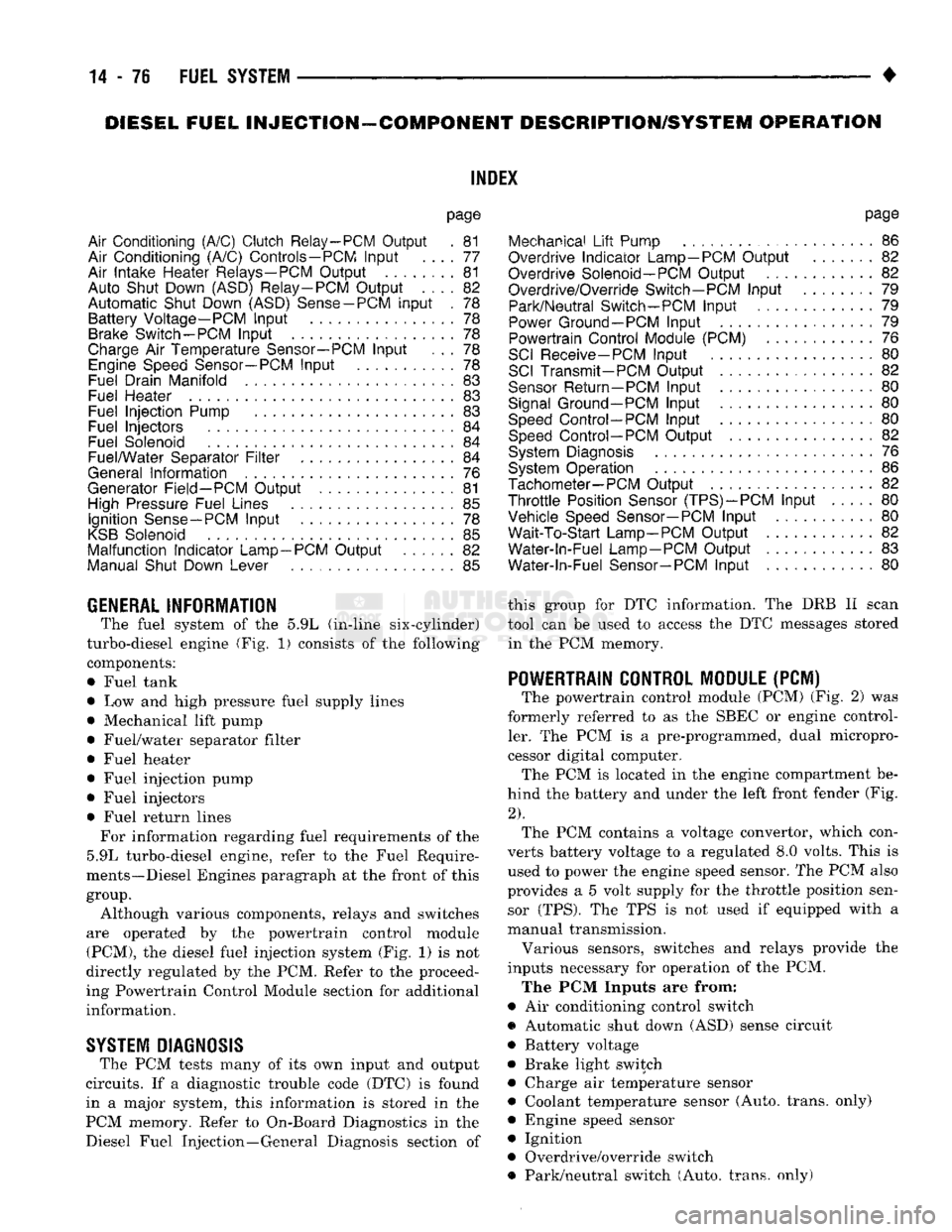
The powertrain control module (PCM) (Fig. 2) was
formerly referred to as the SBEC or engine control ler. The PCM is a pre-programmed, dual micropro
cessor digital computer. The PCM is located in the engine compartment be
hind the battery and under the left front fender (Fig.
2).
The PCM contains a voltage convertor, which con
verts battery voltage to a regulated 8.0 volts. This is used to power the engine speed sensor. The PCM also
provides a 5 volt supply for the throttle position sensor (TPS). The TPS is not used if equipped with a
manual transmission.
Various sensors, switches and relays provide the
inputs necessary for operation of the PCM.
The PCM Inputs are from:
9
Air conditioning control switch
• Automatic shut down (ASD) sense circuit
• Battery voltage
• Brake light switch • Charge air temperature sensor ® Coolant temperature sensor (Auto, trans, only)
• Engine speed sensor
• Ignition
• Overdrive/override switch
• Park/neutral switch (Auto, trans, only)
Page 897 of 1502
14-78
FUEL SYSTEM
• If
the A/C low
pressure switch opens (indicating
a
low refrigerant level),
the PCM
will
not
receive
an
A/C select signal.
The PCM
will then remove
the
ground from
the A/C
relay. This will deactivate
the
A/C compressor clutch.
If evaporator switch opens, (indicating that evapo
rator
is not in
proper temperature range),
PCM
will
not receive
the A/C
request signal.
The PCM
will
then remove
the
ground from
the A/C
relay, deacti
vating
the A/C
compressor clutch.
AUTOMATIC SHUT DOWN
(ASD)
SENSE-PCM
INPUT
A
12
volt signal
at
this input indicates
to the PCM
that
the ASD has
been activated.
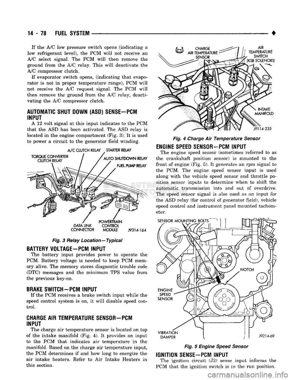
The ASD
relay
is
located
in the
engine compartment
(Fig.
3).
It is
used
to power
a
circuit
to the
generator field winding.
TORQUE
CONVERTER
CLUTCH RELAY A/C
CLUTCH RELAY
.
STARTER RELAY
AUTO
SHUTDOWN
RELAY
FUEL PUMP RELAY
DATA
LINK
CONNECTOR
POWERTRAIN
CONTROL
MODULE
J9314-164
Fig.
3
Relay Location—Typical
BATTERY VOLTAGE-PC! INPUT
The battery input provides power
to
operate
the
PCM. Battery voltage
is
needed
to
keep
PCM
mem
ory alive.
The
memory stores diagnostic trouble code (DTC) messages
and the
minimum
TPS
value from
the previous key-on,
BRAKE
SWITCH-PCM INPUT
If
the PCM
receives
a
brake switch input while
the
speed control system
is on, it
will disable speed con
trol.
CHARGE AIR TEMPERATURE SENSOR—PCM INPUT
The charge
air
temperature sensor
is
located
on top
of
the
intake manifold
(Fig. 4). It
provides
an
input
to
the PCM
that indicates
air
temperature
in the
manifold. Based
on the
charge
air
temperature input,
the
PCM
determines
if and how
long
to
energize
the
air intake heaters. Refer
to Air
Intake Heaters
in
this section. AIR
TEMPERATURE
SWITCH
(KSB
SOLENOID)
j9114-235
Fig.
4
Charge
Air
Temperature Sensor
ENGINE
SPEED
SENSOR-PCM
INPUT
The engine speed sensor (sometimes referred
to as
the crankshaft position sensor)
is
mounted
to the
front
of
engine
(Fig. 5). It
generates
an rpm
signal
to
the
PCM. The
engine speed sensor input
is
used along with
the
vehicle speed sensor
and
throttle
po
sition sensor inputs
to
determine when
to
shift
the
automatic transmission into
and out of
overdrive.
The speed sensor signal
is
also used
as an
input
for
the
ASD
relay
(for
control
of
generator field), vehicle speed control
and
instrument panel mounted tachom
eter.
SENSOR
MOUNTING BOLTS
VIBRATION
DAMPER
J9214-69
Fig.
5
Engine Speed Sensor
IGNITION
SENSE-PCM
INPUT
The ignition circuit
(J2)
sense input informs
the
PCM that
the
ignition switch
is in the run
position.