check transmission fluid DODGE TRUCK 1993 Service Manual Online
[x] Cancel search | Manufacturer: DODGE, Model Year: 1993, Model line: TRUCK, Model: DODGE TRUCK 1993Pages: 1502, PDF Size: 80.97 MB
Page 1322 of 1502
•
TRANSMISSION
0VERHAUL-4IRH
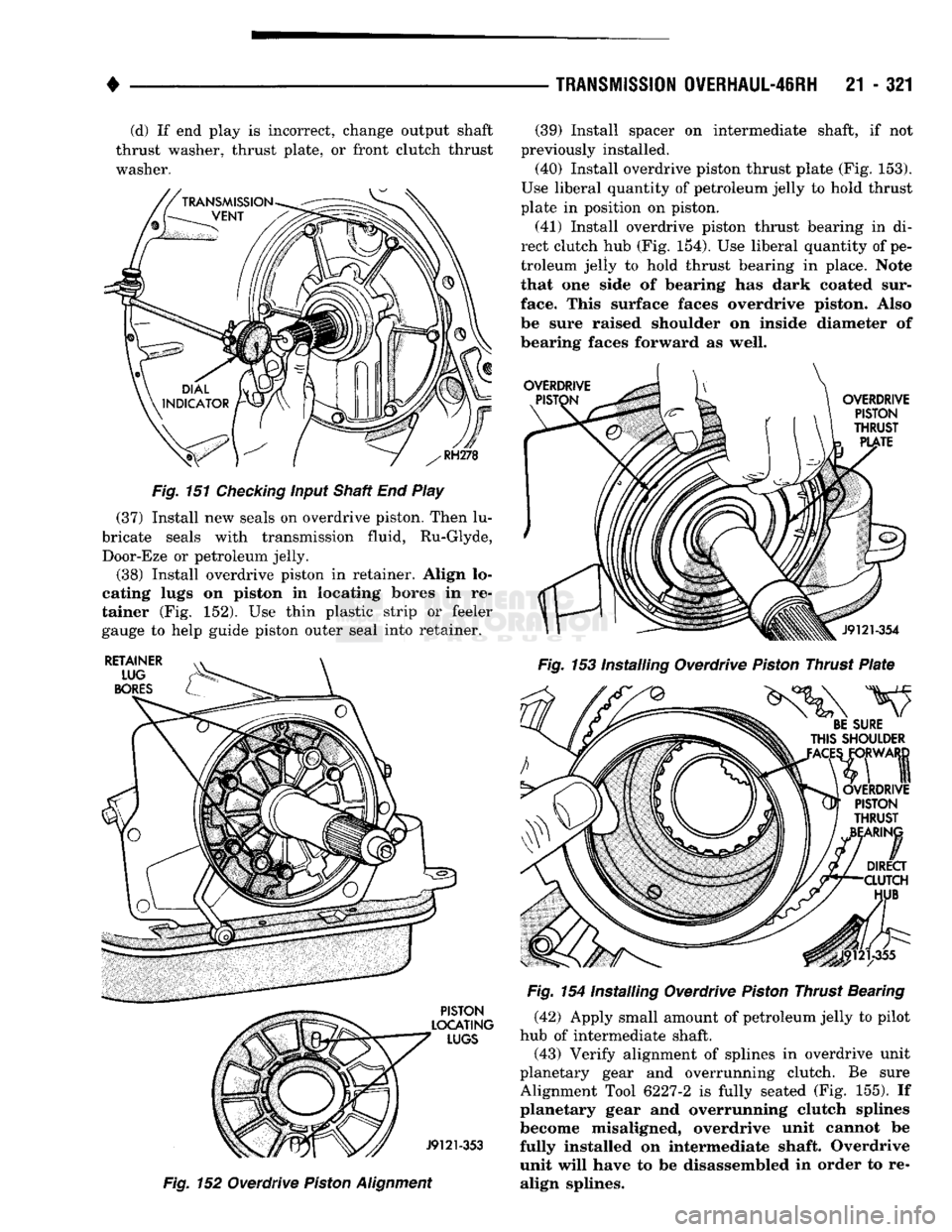
21 - 321 (d) If end play is incorrect, change output shaft
thrust washer, thrust plate, or front clutch thrust washer.
Fig.
151
Checking
input Shaft End Play
(37) Install new seals on overdrive piston. Then lu
bricate seals with transmission fluid, Ru-Glyde, Door-Eze or petroleum jelly.
(38) Install overdrive piston in retainer. Align lo
cating lugs on piston in locating bores in re
tainer (Fig. 152). Use thin plastic strip or feeler
gauge to help guide piston outer seal into retainer.
Fig.
152 Overdrive
Piston
Alignment
(39) Install spacer on intermediate shaft, if not
previously installed. (40) Install overdrive piston thrust plate (Fig. 153).
Use liberal quantity of petroleum jelly to hold thrust
plate in position on piston.
(41) Install overdrive piston thrust bearing in di
rect clutch hub (Fig. 154). Use liberal quantity of pe
troleum jelly to hold thrust bearing in place. Note
that one side of bearing has dark coated sur
face. This surface faces overdrive piston. Also
be sure raised shoulder on inside diameter of
bearing faces forward as well.
Fig.
153 Installing Overdrive
Piston
Thrust
Plate
Fig.
154 Installing Overdrive
Piston
Thrust Bearing (42) Apply small amount of petroleum jelly to pilot
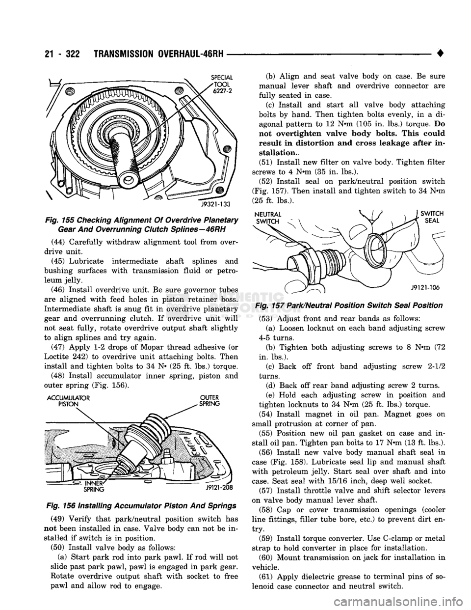
hub of intermediate shaft. (43) Verify alignment of splines in overdrive unit
planetary gear and overrunning clutch. Be sure
Alignment Tool 6227-2 is fully seated (Fig. 155). If
planetary gear and overrunning clutch splines
become misaligned, overdrive unit cannot be
fully installed on intermediate shaft. Overdrive
unit will have to be disassembled in order to re align splines.
Page 1323 of 1502
21
- 322
TRANSMISSION
OVERHAUL-46RH
•
J932M33
Fig.
155
Checking
Alignment
Of Overdrive Planetary
Gear
And Overrunning
Clutch
Splines—46RH
(44) Carefully withdraw alignment tool from over
drive unit.
(45) Lubricate intermediate shaft splines and
bushing surfaces with transmission fluid or petro leum jelly.
(46) Install overdrive unit. Be sure governor tubes
are aligned with feed holes in piston retainer boss.
Intermediate shaft is snug fit in overdrive planetary
gear and overrunning clutch. If overdrive unit will
not seat fully, rotate overdrive output shaft slightly
to align splines and try again.
(47) Apply 1-2 drops of Mopar thread adhesive (or
Loctite 242) to overdrive unit attaching bolts. Then
install and tighten bolts to 34 N» (25 ft. lbs.) torque.
(48) Install accumulator inner spring, piston and
outer spring (Fig. 156).
ACCUMULATOR
OUTER
Fig.
156 Installing
Accumulator
Piston
And
Springs
(49) Verify that park/neutral position switch has
not been installed in case. Valve body can not be in stalled if switch is in position.
(50) Install valve body as follows: (a) Start park rod into park pawl. If rod will not
slide past park pawl, pawl is engaged in park gear.
Rotate overdrive output shaft with socket to free
pawl and allow rod to engage. (b) Align and seat valve body on case. Be sure
manual lever shaft and overdrive connector are
fully seated in case.
(c) Install and start all valve body attaching
bolts by hand. Then tighten bolts evenly, in a di agonal pattern to 12 Nnn (105 in. lbs.) torque. Do
not overtighten valve body bolts. This could result in distortion and cross leakage after in stallation..
(51) Install new filter on valve body. Tighten filter
screws to 4 Nnn (35 in. lbs.).
(52) Install seal on park/neutral position switch
(Fig. 157). Then install and tighten switch to 34 Nnn
(25 ft. lbs.).
Fig.
157 Park/Neutral Position
Switch
Seal
Position
(53) Adjust front and rear bands as follows:
(a) Loosen locknut on each band adjusting screw
4-5 turns.
(b) Tighten both adjusting screws to 8 Nnn (72
in. lbs.).
(c) Back off front band adjusting screw 2-1/2
turns.
(d) Back off rear band adjusting screw 2 turns.
(e) Hold each adjusting screw in position and
tighten locknuts to 34 Nnn (25 ft. lbs.) torque.
(54) Install magnet in oil pan. Magnet goes on
small protrusion at corner of pan.
(55) Position new oil pan gasket on case and in
stall oil pan. Tighten pan bolts to 17 Nnn (13 ft. lbs.).
(56) Install new valve body manual shaft seal in
case (Fig. 158). Lubricate seal lip and manual shaft
with petroleum jelly. Start seal over shaft and into
case.
Seat seal with 15/16 inch, deep well socket.
(57) Install throttle valve and shift selector levers
on valve body manual lever shaft. (58) Cap or cover transmission openings (cooler
line fittings, filler tube bore, etc.) to prevent dirt en
try.
(59) Install torque converter. Use C-clamp or metal
strap to hold converter in place for installation. (60) Mount transmission on jack for installation in
vehicle.
(61) Apply dielectric grease to terminal pins of so
lenoid case connector and neutral switch.
Page 1334 of 1502
•
OVERDRIVE
UNIT
OVERHAUL—42RH/46RH
21 - 333 Check the machined surfaces on the output shaft.
These surfaces should clean and smooth. Very minor nicks or scratches can be smoothed with crocus cloth.
Replace the shaft if worn, scored or damaged in any
way.
Check condition of the governor components. Re
place the governor drive seal rings if damaged. Be sure the drive ring grooves are in good condition. Check operation of the governor valve, weights and
shaft. The valves and weights should slide freely in
the governor body (Fig. 36).
There are two governor component changes in
current overdrive unit units. The first involves
the governor valve which is now made of alumi
num. The second involves the output shaft which has a spotface for governor valve end
clearance. The new aluminum valve is not inter
changeable. It must only be used with an output
shaft that has the spotface for valve end clear ance.
Inspect the governor support and the two oil pres
sure tubes (Fig. 36). The tubes are an integral
part of the support. Do not attempt to remove
them.
The oil tubes must not be pinched, kinked, col
lapsed, or distorted. Blow them out with compressed
air to be sure they are clear. The tubes are designed
to be a slip fit in the piston retainer boss. Do not modify the tube ends in an effort to make them fit
tighter.
Replace the governor support and the oil tubes as
an assembly if either component is damaged.
Check condition of the governor valve and weight
snap rings. Replace any snap ring that appears bent
or distorted. Replace any snap ring if its condition is
doubtful.
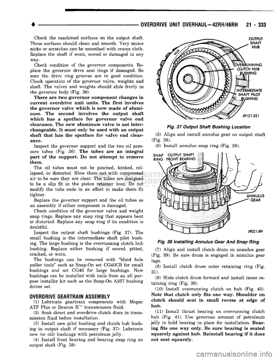
Inspect the output shaft bushings (Fig. 37). The
small bushing is the intermediate shaft pilot bush
ing. The large bushing is the overrunning clutch hub
bushing. Replace either bushing if scored, pitted, cracked, or worn.
The bushings can be removed with "blind hole
puller tools" such as Snap-On set CG40CB for small
bushings and set CG46 for large bushings. New
bushings can be installed with tools from an all pur
pose installer kit such as the Snap-On A257 bushing driver set.
OVERDRIVE
GEARTRAIN
ASSEMBLY
(1) Lubricate geartrain components with Mopar
ATF Plus or Dexron II™ transmission fluid. (2) Soak direct and overdrive clutch discs in trans
mission fluid before installation. (3) Install new pilot bushing and clutch hub bush
ing in output shaft if necessary (Fig. 37). Lubricate
new (or old) bushings with petroleum jelly. (4) Install front bearing and bearing snap ring on
output shaft (Fig. 38)
Fig.
37 Output Shaft
Bushing
Location
(5) Align and install annulus gear on output shaft
(Fig. 38). (6) Install annulus snap ring (Fig. 38).
Fig.
38 Installing
Annulus
Gear And
Snap Ring
(7) Align and install clutch drum on annulus gear
(Fig. 39). Be sure drum is engaged in annulus gear
lugs.
(8) Install clutch drum outer retaining ring (Fig.
31).
(9) Slide clutch drum forward and install inner re
taining ring (Fig. 39).
(10) Install overrunning clutch on hub (Fig. 40).
Note that clutch only fits one way. Shoulder on
clutch should seat in small recess at edge of
hub.
(11) Install thrust bearing on overrunning clutch
hub (Fig. 41). Use generous amount of petroleum
jelly to hold bearing in place for installation. Bear ing fits one way only. Be sure bearing is seated squarely against hub. Reinstall bearing if it does
not seat squarely.
Page 1344 of 1502
•
NP205 TRANSFER
CASE
21 - 343 Leakage from other sources (engine, transmission,
etc.) can be blown back onto the transfer case by air
flow under the vehicle. A blocked transfer case vent
can also cause leakage at the shaft seals due to in
ternal pressure build up.
Overfilling the transfer case can force fluid out the
vent and be mistaken for a leak. Correct fluid level checking methods should prevent overfill problems.
Checking
Fluid Level The correct method of checking transfer case fluid
level requires that the vehicle be level.
If fluid level is checked with the vehicle parked on
the shop floor, be sure the floor area used is level. If a hoist is used, a drive-on, or swivel arm type is pre
ferred.
Allow the transfer case fluid to settle for a minute
or so before checking. Correct fluid level is to the
bottom edge of the fill plug hole.
HARD SHIFTING
Hard shifting is generally caused by:
• misadjusted or binding linkage
• loose linkage or driveline components
• torque loads caused by 4WD operation on hard
paved surfaces • improper shifting techniques
• lack of lubricant which caused internal wear and
damage.
Loose linkage or driveline components are a result
of improperly tightened, stripped, or missing fasten
ers.
Remember that loose crossmember and mounting
parts can also generate a hard shift condition.
Torque loads in the transfer case can cause hard
shifting or even prevent shifting. Such loads are gen
erally a product of extensive operation on hard,
paved surfaces in 4WD range, unequal size tires, or
by mismatched front/rear axle gear ratios.
Linkage adjustment should be performed as de
scribed in the service section. Improper shift and op
erating techniques can be corrected by instructing
the driver. Internal component damage will require
overhaul to correct.
Failure to lubricate the shift linkage at recom
mended intervals will cause the linkage to bind. If
bind is severe enough to cause hard shifting, the linkage will have to be removed in order to correct
the condition. The linkage can be soaked in auto
matic transmission fluid if necessary. The fluid will
break up accumulated rust and corrosion.
NOISE
Some transfer case operating noise is normal. The
rotating gear train can produce sounds that may be
come audible at higher speeds and loads. However,
unusual noise is an indicator that internal compo nents may be worn or damaged. Low lubricant levels are a frequent cause of noisy
operation. Insufficient lubricant will lead to over
heating, subsequent damage to bearing and gear sur
faces and hard shifting.
Transfer case bearing noise is higher in pitch than
gear noise. If the unit is noisy in 4WD range only,
the front shaft bearings are probably at fault. If the unit is noisy in all ranges, an overhaul will be nec
essary to locate the faulty bearing.
Gear noise is lower in pitch and usually most no
ticeable when engaged and under load. Gear noise in
4WD drive range only is an indicator that the front shaft gears are damaged. Noise in all ranges could be
the idler or drive gears. An overhaul will be neces sary to determine which is at fault.
Frequently, suspected transfer case noise may actu
ally originate from another driveline component. The
proximity of other driveline components can some
times make it difficult to pinpoint the noise source.
TRANSFER CASE OPERATIONAL CHECK
The transfer case should not be removed until di
agnosis indicates the unit has actually malfunc
tioned. If a transfer case problem is suspected, check and verify operation before attempting repair. A
transfer case operational check may reveal that a
problem is actually related to another driveline com ponent.
(1) Raise vehicle on a hoist that will allow all four
wheels to rotate. (2) Check lubricant level. If lubricant level is low,
check for leaks at the bearing and seal retainers,
yokes,
drain/fill plugs, PTO cover and vent. (3) If vehicle is equipped with locking hubs, en
gage hubs. (4) Start engine, shift transmission into gear and
operate transfer case in all ranges. Observe propeller shaft action, shift efforts and operational sound lev
els as follows: (a) Only the rear propeller shaft should rotate in
two-wheel drive. Both propeller shafts should both
rotate in four-wheel drive high and low ranges. (b) If the front propeller shaft did not rotate in
either four-wheel drive range, the transfer case shift components may be worn or damaged. Or, if
the front shaft did rotate but the front wheels did
not, check the front axle shift mechanism and the locking hubs (if equipped). (c) If both propeller shafts rotate in four-wheel
drive but the wheels on one axle did not rotate, the
problem is in the axle. (d) If neither propeller shaft rotates in any
range, the problem is in the transmission or trans fer case. To determine which component is at fault,
proceed to next step. (5) Determine if fault is with transfer case or
transmission as follows:
Page 1351 of 1502
21 - 350 NP241
TRANSFER CASE
• NP241 TRANSFER CASE
INDEl
page
Checking
Fluid
Level
351
Component Cleaning
and
Inspection
359
Fluid
Drain/Refill
351
General
Information
350
Recommended
Lubricant
.................. 350
Service
Diagnosis
....................... 350
Shift
Linkage
Adjustment
354
Speedometer Adapter/Distance
Sensor
Service
. 352
page
Speedometer Gear, Shaft
Seal,
Bearing
and
Retainer
Service
352
Transfer
Case
Assembly
.................. 361
Transfer
Case
Bearing Replacement
......... 360
Transfer
Case
Disassembly
................ 356
Transfer
Case
Identification ................ 350
Transfer
Case
Installation
................. 356
Transfer
Case
Removal
356
GENERAL
INFORMATION
The NP241 is a part-time transfer case with a low-
range gear system. It has three operating ranges
plus a Neutral position. The low range system pro vides a gear reduction ratio for increased low speed
torque capability. NP241 operating ranges are: 2-high, 4-high and 4-low. The NP241 has an aluminum, two-piece gear case.
Drive sprockets and an interconnecting drive chain are used to transmit engine torque to the propeller
shafts.
Four-wheel high and low ranges are undifferenti
ated. The transfer case is not designed for continuous
operation in 4WD range on hard or paved surfaces.
Four wheel drive ranges are recommended for off
road operation, or on snow covered or similar low
traction surfaces. A front axle disconnect system is used to achieve
two-wheel drive mode. The axle disconnect vacuum motor is actuated by a vacuum switch on the transfer
case.
The switch is operated by the transfer case
range rod. Two-wheel drive range is used for on road, high
way operation. The four-wheel drive ranges are for off road operation or when the vehicle is driven on
paved road surfaces covered by snow, ice or similar low traction elements.
TRANSFER CASE
IDENTIFICATION
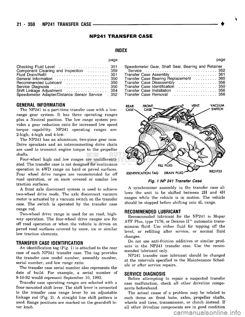
An identification tag (Fig, 1) is attached to the rear
case of each NP241 transfer case. The tag provides
the transfer case model number, assembly number, serial number, and low range ratio. The transfer case serial number also represents the
date of build. For example, a serial number of 9-10-92 would represent September 10, 1992. Transfer case operating ranges are selected with a
floor-mounted shift lever. The shift lever is connected
to the transfer case range lever by an adjustable linkage rod (Fig. 2). A straight line shift pattern is
used. Range positions are marked on the gearshift le
ver knob.
Fig.
1 NP 241 Transfer
Case
A synchronizer assembly in the transfer case al
lows the unit to be shifted between 2H and 4H
ranges while the vehicle is in motion. The vehicle should be stopped before shifting into 4L range.
RECOMMENDED
LUBRICANT
Recommended lubricant for the NP241 is Mopar
ATF Plus, type 7176, or Dexron II™ automatic trans
mission fluid. Use either fluid for topping off the
level, or refilling after service, or normal fluid
changes. Do not use anti-friction additives or similar prod
ucts in the NP241 transfer case. Use the recom
mended lubricant only. NP241 transfer case lubricant should be changed
at the intervals specified in the Maintenance Sched
ule or after service repairs.
SERVICE
DIAGNOSIS
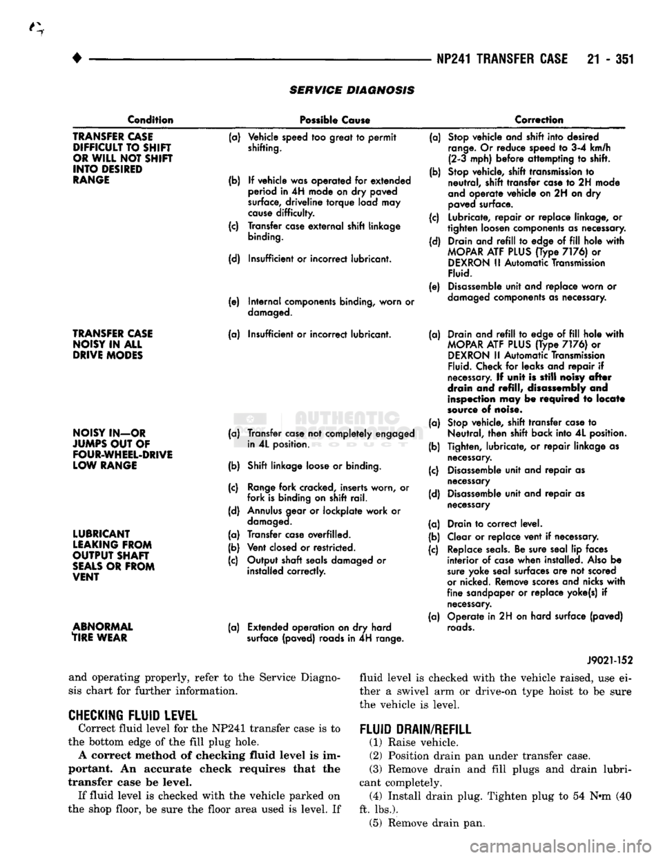
Before attempting to repair a suspected transfer
case malfunction, check all other driveline compo
nents beforehand. The actual cause of a problem may be related to
such items as: front hubs, axles, propeller shafts,
wheels and tires, transmission, or clutch instead. If all other driveline components are in good condition
Page 1352 of 1502
•
NP241 TRANSFER CASE
21 - 351
SERVICE
DIAGNOSIS
Condition
Possible
Cause
Correction
TRANSFER
CASE
DIFFICULT
TO
SHIR
OR
WILL
NOT
SHIFT
INTO
DESIRED
RANGE
TRANSFER
CASE
NOISY
IN ALL
DRIVE
MODES
NOISY
IN-OR
JUMPS
OUT
OF
FOUR-WHEEL-DRIVE
LOW
RANGE
LUBRICANT
LEAKING
FROM
OUTPUT
SHAFT
SEALS
OR
FROM
VENT
ABNORMAL
TIRE
WEAR
(a)
Vehicle speed
too
great
to permit
shifting.
(b)
If
vehicle was operated
for
extended
period
in 4H
mode
on dry
paved
surface,
driveline
torque
load
may
cause
difficulty.
(c) Transfer
case
external
shift linkage
binding.
(d) Insufficient
or
incorrect lubricant.
(e) Internal components binding, worn
or
damaged.
(a) Insufficient
or
incorrect lubricant.
(a) Transfer
case
not
completely engaged in
4L
position.
(b) Shift linkage
loose
or
binding.
(c)
Range
fork cracked, inserts worn,
or
fork is binding
on
shift rail.
(d)
Annulus
gear
or
lockplate work
or
damaged.
(a) Transfer
case
overfilled.
(b) Vent
closed
or
restricted.
(c) Output shaft
seals
damaged
or
installed correctly.
(a) Extended operation
on dry
hard
surface
(paved) roads
in 4H
range. (a)
Stop
vehicle and shift into desired
range.
Or
reduce speed
to 3-4
km/h (2-3 mph) before attempting
to
shift.
(b)
Stop
vehicle, shift
transmission
to
neutral, shift transfer
case
to 2H
mode
and
operate vehicle on
2H on dry
paved
surface.
(c) Lubricate, repair
or
replace linkage,
or
tighten loosen components as necessary.
(d) Drain and
refill to
edge
of fill
hole
with
MOPAR
ATF
PLUS
(Type
7176) or
DEXRON
II
Automatic
Transmission
Fluid.
(e)
Disassemble
unit and replace worn
or
damaged
components
as necessary.
(a) Drain and
refill to
edge
of fill
hole
with
MOPAR
ATF
PLUS
(Type
7176) or
DEXRON
II
Automatic
Transmission
Fluid.
Check
for
leaks and repair
if
necessary.
If
unit
is
still
noisy
after
drain
and
refill,
disassembly
and
inspection
may be
required
to
locate
source
of
noise.
(a)
Stop
vehicle, shift transfer
case
to
Neutral, then shift back into
4L
position.
(b) Tighten, lubricate,
or
repair linkage
as
necessary.
(c)
Disassemble
unit and repair
as
necessary
(d)
Disassemble
unit and repair
as
necessary
(a) Drain
to
correct level.
(b) Clear
or
replace vent
if
necessary.
(c) Replace
seals.
Be sure seal
lip
faces interior
of
case
when installed.
Also
be
sure
yoke seal surfaces
are not
scored
or
nicked. Remove
scores
and nicks
with
fine sandpaper
or
replace yoke(s)
if
necessary.
(a) Operate
in 2H on
hard surface (paved)
roads.
and operating properly, refer to the Service Diagno
sis chart for further information.
CHECKING FLUID LEVEL
Correct fluid level for the NP241 transfer case is to
the bottom edge of the fill plug hole. A correct method of checking fluid level is im
portant. An accurate check requires that the
transfer case be level. If fluid level is checked with the vehicle parked on
the shop floor, be sure the floor area used is level. If J9021-152
fluid level is checked with the vehicle raised, use ei
ther a swivel arm or drive-on type hoist to be sure
the vehicle is level.
FLUID DRAIN/REFILL
(1) Raise vehicle.
(2) Position drain pan under transfer case.
(3)
Remove drain and fill plugs and drain lubri
cant completely. (4) Install drain plug. Tighten plug to 54 N»m (40
ft. lbs.). (5) Remove drain pan.
Page 1354 of 1502
•
NP241 TRANSFER
CASE
21 - 313
LOCK OIL RING SEAL
ADAPTER
(OVERDRIVE
ONLY)
SPEEDOMETER
PINION
GEAR
ADAPTER
O-RING
SPEEDOMETER
ADAPTER
RETAINER
DISTANCE
SENSOR
J9021-99
Fig.
4 Speedometer
Components
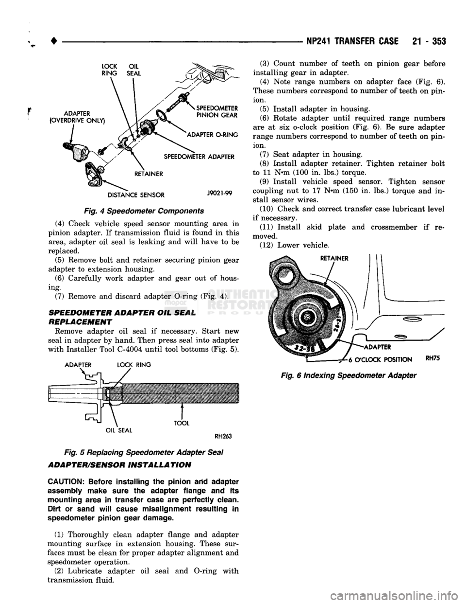
(4) Check vehicle speed sensor mounting area in
pinion adapter. If transmission fluid is found in this area, adapter oil seal is leaking and will have to be
replaced.
(5) Remove bolt and retainer securing pinion gear
adapter to extension housing.
(6)
Carefully work adapter and gear out of hous
ing. (7) Remove and discard adapter O-ring (Fig. 4).
SPEEDOMETER ADAPTER
OIL
SEAL
REPLACEMENT
Remove adapter oil seal if necessary. Start new
seal in adapter by hand. Then press seal into adapter
with Installer Tool C-4004 until tool bottoms (Fig. 5).
ADAPTER
LOCK
RING
TOOL
(3) Count number of teeth on pinion gear before
installing gear in adapter.
(4) Note range numbers on adapter face (Fig. 6).
These numbers correspond to number of teeth on pin ion. (5) Install adapter in housing.
(6)
Rotate adapter until required range numbers
are at six o-clock position (Fig. 6). Be sure adapter
range numbers correspond to number of teeth on pin ion. (7) Seat adapter in housing.
(8) Install adapter retainer. Tighten retainer bolt
to 11 N-m (100 in. lbs.) torque.
(9) Install vehicle speed sensor. Tighten sensor
coupling nut to 17 N-m (150 in. lbs.) torque and in
stall sensor wires.
(10) Check and correct transfer case lubricant level
if necessary.
(11) Install skid plate and crossmember if re
moved. (12) Lower vehicle.
ADAPTER
O'CLOCK
POSITION
Fig.
6 Indexing Speedometer Adapter
RH75
OIL
SEAL
RH263
Fig.
5
Replacing
Speedometer Adapter
Seal
ADAPTER/SENSOR
INSTALLATION
CAUTION:
Before installing
the
pinion arid adapter
assembly
make sure
the
adapter flange
and its
mounting area
in
transfer case
are
perfectly clean. Dirt
or
sand
will
cause misalignment resulting
in
speedometer pinion gear damage.
(1) Thoroughly clean adapter flange and adapter
mounting surface in extension housing. These sur
faces must be clean for proper adapter alignment and speedometer operation.
(2) Lubricate adapter oil seal and O-ring with
transmission fluid.