key battery DODGE TRUCK 1993 Service Repair Manual
[x] Cancel search | Manufacturer: DODGE, Model Year: 1993, Model line: TRUCK, Model: DODGE TRUCK 1993Pages: 1502, PDF Size: 80.97 MB
Page 25 of 1502
0 - 6
LUBRICATION
AND
MAINTENANCE
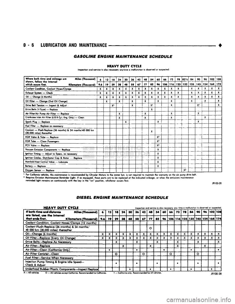
GASOLINE ENGINE MAINTENANCE SCHEDULE
HEAVY
DUTY
CYCLE
Inspection and service is also necessary anytime
a
malfunction is observed or suspected.
When both
time
and mileage
are
Miles (Thousand)
shewn,
follow
the
interval
which occurs first. Kilometers (Thousand) 6
12 18 24
30 36 42 48 54
60 66 72
78
82V2
84 90
96
102 108
When both
time
and mileage
are
Miles (Thousand)
shewn,
follow
the
interval
which occurs first. Kilometers (Thousand) 9.6 19 29
38 48 58 67 77
85 96 106 116
125 132
135
145
154 164
174
Coolant
Condition, Coolant
Hoses/Clamps
X
X X X
X X X X
X X X X
X X X
X X X
Exhaust
System
—
Check
X X X X X X X X X X X
X X X X X
X X
Oil
—
Change
(6
Months)
X X X X X X X
X X
X
X
X
X X X
X X
X
Oil
Filter
—
Change (2nd
Oil
Change)
X X X X
X X
X X
X
Drive Belt Tension
—
Inspect
&
Adjust
X' X
X1
X X' X
Drive Belts (V-Type)
—
Replace
X
Air
Filter/Air
Pump
Air
Filter
—
Replace
X X X
X
Crankcase
Inlet
Air
Filter
(6 &
8
Cyl.
Eng.
Only)
—
Clean
X X
X X
Spark
Plug
—
Replace
X X X
Fuel
Filter
—
Replace as necessary
Coolant
—
Flush/Replace
(36
months)
& 24
months/48
000 km
(30,000
miles)
thereafter
X
EGR
Valve
&
Tube
—
Replace X2
EGR
Tube
—
Clean Passengers
X2
PCV
Valve
—
Replace X2
Vacuum
Emission
Components
—
Replace
X
Ignition Timing
—
Adjust
to
Specs,
as necessary X
Ignition Cables, Distributor Cap
&
Rotor
—
Replace
X
Manifold Heat Control Valve
—
Lubricate
X
Battery
—
Replace X
Oxygen
Sensor
—
Replace
X2
1 For California vehicles, this maintenance is recommended
by
Chrysler Motors
to the
owner but, is not
required
to
maintain the
warranty
on the
air
pump drive
belt.
2 Requires
Emission
Maintenance Reminder Light.
If
so equipped, these parts
are to be
replaced
at the
indicated mileage,
or
when the
emissions
maintenance reminded light remains on continuously
with
the key in the
"on" position, whichever occurs first.
J9100-20
DIESEL
ENGINE
MAINTENANCE
SCHEDULE
HEAVY
DUTY
CYCLE
Inspection
and
service
is
also
necessary
any
time
a
malfunction
is
observed
or
suspected.
Iff both
time
and distance Miles (Thousand)
are listed, use the
interval
that
ends
first. Kilometers (Thousand) 6
12
18 24
30 36 42
4S
54
60 66
72 78
84 90 96
102 108
Iff both
time
and distance Miles (Thousand)
are listed, use the
interval
that
ends
first. Kilometers (Thousand) 9,6 19
29
38 48 58 67
77
85 96 106
116 125 135 145 154
164 174
Coolant
Condition, Coolant
Hoses/Clamps
(12 months)
Coolant
Flush/Replace (36 months) & 24 months/
48 000 km
(30,000
miles)
thereafter
O
Oil—Change
(6 months)
X X X
X X X
X X X X X
X X X X X X
X
Oil Filter—Replace (Every Oil Change)
X X X
X X X
X X
X X X
X
X X X X
X X
Drive Belts—Replace
As
Necessary
X X
X X X X
Air Filter—Replace
X X
X X
Air Filter—Clean (California Only) e
®
• •
Air
Filter
Canister—Clean
o o o
o
Fuel Filter—Service When Necessary
Injection
Pump
Timing & Engine Idle Speed—
Check
& Adjust
©
• 9 • • •
Underhood Rubber/Plastic Components—Inspect/Replace • • • • •
X
— All vehicles
O
— All
vehicles
except
California.
Recommended
for
California.
•
— California only.
Recommended
for all vehicles.
Page 325 of 1502
8A
- 4
ELECTRICAL
•
IGNITION
OFF
DRAW
(IOD)
Ignition off draw refers to power being drained
from the battery with the ignition turned off. A nor
mal vehicle electrical system will draw from 5 to 20
milliamps. A vehicle that has not been operated for
an extended period of time (approximately 20 days)
may discharge the battery to an inadequate level.
Battery drain should not exceed approximately 20
MA (20 milliamps = 0.020 amps). The 20 MA are needed to supply PCM memory,
digital clock memory, and ETR (electronically tuned
radio) memory. Excessive battery drain is caused by items left
turned on, internally shorted generator, or intermit
tent short in wiring.
If the IOD is excessive (over 20 milliamperes), the
defect must be found and corrected before replacing a
battery. In most cases the battery can be charged and returned to service.
TEST PROCEDURE Testing for higher amperage IOD must be per
formed first to prevent damage to most milliamp
meters.
Verify that all electrical accessories are OFF. Turn
off all lights, remove ignition key, and close all
doors.
If the vehicle is equipped with electronic acces
sories (illuminated entry, high line radio), allow the
systems to automatically shut off (time out), up to 3
minutes.
(1) After determining that the underhood lamp is
operating properly then disconnect bulb. (2) Disconnect negative cable from battery.
(3) Connect a typical 12 volt test light (low watt
age bulb) between the negative cable clamp and the
battery negative terminal. The test light may light brightly for up to 3 min
utes or may not light at all (depending on the elec
trical equipment). The term brightly being used
throughout the following tests, implies the bright ness of the test light will be the same as if it were
connected across the battery.
The test light must be securely clamped to the neg
ative cable and battery terminal. If the test light be
comes disconnected during any of the IOD test, the electronic timer function will be activated and all
tests must be repeated.
(4) After 3 minutes, the test light should turn OFF
or be DIMLY lit (depending on the electrical equip
ment).
If the test light remains brightly lit do not
disconnect it. Remove each fuse or circuit breaker (refer to Group 8 - Wiring Diagrams) until test light
is either OFF or DIMLY lit. This will eliminate the
higher amperage draw.
If test light is still bright after disconnecting each
fuse and circuit breaker, disconnect the wiring har ness from the generator. Refer to Generator Testing
in this group. Do not disconnect the test light. After higher amperage IOD has been corrected, low
amperage IOD may be checked.
It is now safe to install milliamp meter to check for
low amperage IOD.
(5) With test light still connected, securely clamp
an ammeter between battery negative terminal and
negative battery cable.
If the test light or the milliamp meter circuit is
broken the various timer circuits will start. Do
not open any doors or turn on any electrical ac cessories with the test light disconnected or the
meter may be damaged.
(6) Disconnect test light. The current draw should
not exceed 0.020 amp. If it exceeds 20 milliamps iso
late each circuit by removing circuit breakers and
fuses.
The meter reading drops once the high current
problem is found. Repair this section of the circuit,
whether it is a wiring short or component failure.
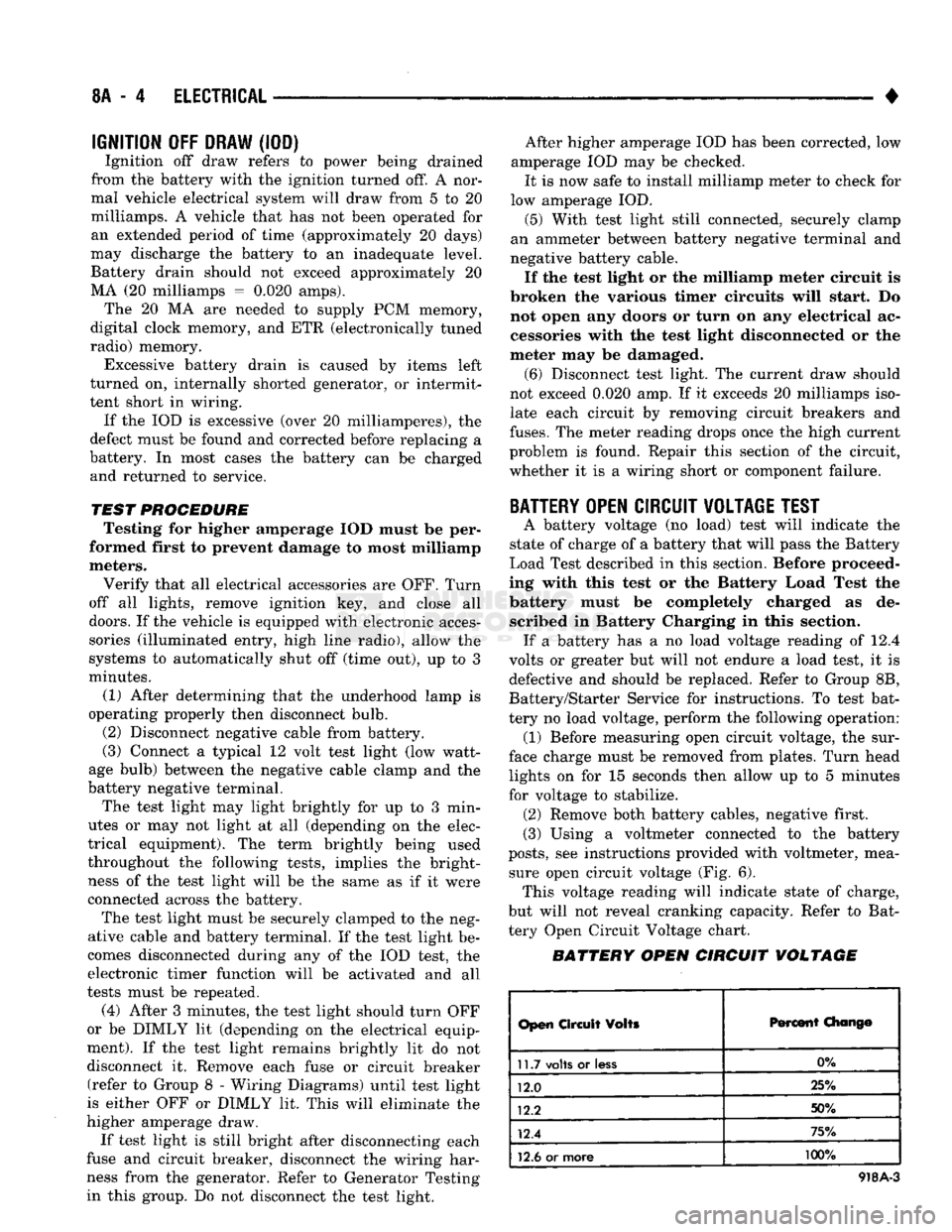
BATTERY
OPEN CIRCUIT VOLTAGE TEST
A battery voltage (no load) test will indicate the
state of charge of a battery that will pass the Battery
Load Test described in this section. Before proceed
ing with this test or the Battery Load Test the
battery must be completely charged as de scribed in Battery Charging in this section. If a battery has a no load voltage reading of 12.4
volts or greater but will not endure a load test, it is
defective and should be replaced. Refer to Group 8B,
Battery/Starter Service for instructions. To test bat
tery no load voltage, perform the following operation: (1) Before measuring open circuit voltage, the sur
face charge must be removed from plates. Turn head lights on for 15 seconds then allow up to 5 minutes
for voltage to stabilize. (2) Remove both battery cables, negative first.
(3) Using a voltmeter connected to the battery
posts,
see instructions provided with voltmeter, mea sure open circuit voltage (Fig. 6). This voltage reading will indicate state of charge,
but will not reveal cranking capacity. Refer to Bat
tery Open Circuit Voltage chart.
BATTERY OPEN CIRCUIT VOLTAGE
Open
Circuit
Volts
Percent
Chang©
11.7
volts
or
less
0%
12.0 25%
12.2 50%
12.4 75%
12.6
or more 100%
918A-3
Page 330 of 1502
•
ELECTRICAL
8A - 9
ENGINE STARTER MOTOR TEST PROCEDURES
GENERAL INFORMATION
The starting system consists of an:
• ignition switch
• starter relay
• park/neutral position switch (automatic transmis sion)
• clutch switch (diesel engine-manual transmission)
• wiring harness
• battery
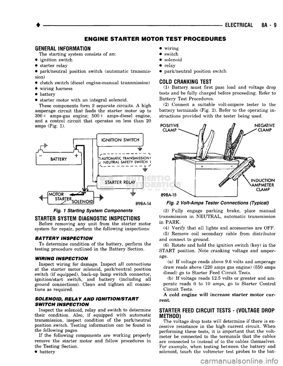
• starter motor with an integral solenoid. These components form 2 separate circuits. A high
amperage circuit that feeds the starter motor up to
300+ amps-gas engine; 500+ amps-diesel engine,
and a control circuit that operates on less than 20
amps (Fig. 1).
a.
BATTERY +
1
IGNITION
SWITCH 1 AUTOMATIC TRANSMISSION
•
J
NEUTRAL SAFETY SWITCH
I 4-
"JL"
MOTOR
m, ...
STA3-TERSOLENO,Dnlh
STARTER RELAY
1"
898A-14
Fig.
1 Starting
System
Components
STARTER SYSTEM DIAGNOSTIC INSPECTIONS
Before removing any unit from the starter motor
system for repair, perform the following inspections:
BATTERY
INSPECTION
To determine condition of the battery, perform the
testing procedure outlined in the Battery Section.
WIRING INSPECTION
Inspect wiring for damage. Inspect all connections
at the starter motor solenoid, park/neutral position
switch (if equipped), back-up lamp switch connector,
ignition/start switch, and battery (including all
ground connections). Clean and tighten all connec
tions as required.
SOLENOID, RELAY
AND
IGNITION/START
SWITCH
INSPECTION
Inspect the solenoid, relay and switch to determine
their condition. Also, if equipped with automatic
transmission, inspect condition of the park/neutral position switch. Testing information can be found in
the following pages.
If the following components are working properly
remove the starter motor and follow procedures in
the Testing Section. • battery wiring
switch
solenoid
relay
park/neutral position switch
COLD CRANKING TEST
(1) Battery must first pass load and voltage drop
tests and be fully charged before proceeding. Refer to Battery Test Procedures. (2) Connect a suitable volt-ampere tester to the
battery terminals (Fig. 2). Refer to the operating in structions provided with the tester being used.
POSITIVE
CLAMP
898A-15
NEGATIVE
CLAMP
INDUCTION
AMPMETER
CLAMP
Fig.
2
Volt-Amps
Tester
Connections
(Typical)
(3) Fully engage parking brake, place manual
transmission in NEUTRAL, automatic transmission
in PARK. (4) Verify that all lights and accessories are OFF. (5) Remove coil secondary cable from distributor
and connect to ground.
(6) Rotate and hold the ignition switch (key) in the
START position. Note cranking voltage and amper
age.
(a) If voltage reads above 9.6 volts and amperage
draw reads above (220 amps gas engine) (550 amps
diesel) go to Starter Feed Circuit Tests. (b) If voltage reads 12.5 volts or greater and am-
perate reads 0 to 10 amps, go to Starter Control Circuit Tests.
A cold engine will increase starter motor cur
rent.
STARTER
FEED
CIRCUIT TESTS
-
(W0LTAGE
DROP
METHOD)
The voltage drop tests will determine if there is ex
cessive resistance in the high current circuit. When
performing these tests, it is important that the volt meter be connected to the terminals that the cables are connected to instead of to the cables themselves.
For example, when testing between the battery and
solenoid, touch the voltmeter test probes to the bat-
Page 332 of 1502
•
ELECTRICAL
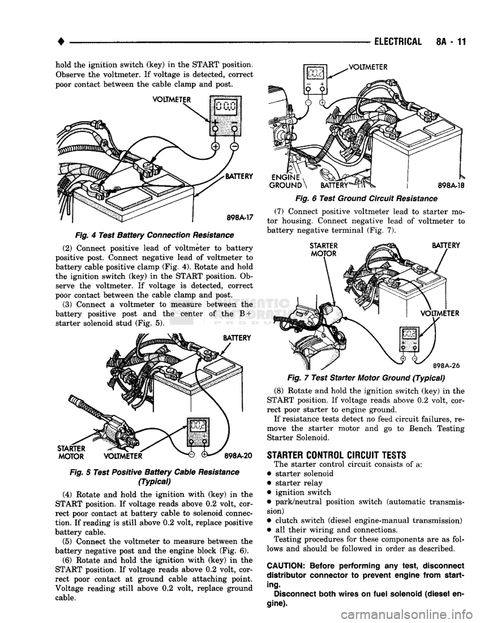
8A - 11 hold the ignition switch (key) in the START position.
Observe the voltmeter. If voltage is detected, correct
poor contact between the cable clamp and post.
VOLTMETER
VOLTMETER
BATTERY
898A-17
Fig.
4 Test
Battery
Connection
Resistance
(2) Connect positive lead of voltmeter to battery
positive post. Connect negative lead of voltmeter to
battery cable positive clamp (Fig. 4). Rotate and hold
the ignition switch (key) in the START position. Ob serve the voltmeter. If voltage is detected, correct
poor contact between the cable clamp and post.
(3) Connect a voltmeter to measure between the
battery positive post and the center of the B + starter solenoid stud (Fig. 5).
BATTERY
STARTER
MOTOR
VOLTMETER
898A-20
Fig.
5 Test Positive
Battery
Cable
Resistance
(Typical)
(4) Rotate and hold the ighition with (key) in the
START position. If voltage reads above 0.2 volt, cor
rect poor contact at battery cable to solenoid connec
tion.
If reading is still above 0.2 volt, replace positive
battery cable.
(5) Connect the voltmeter to measure between the
battery negative post and the engine block (Fig. 6).
(6) Rotate and hold the ignition with (key) in the
START position. If voltage reads above 0.2 volt, cor
rect poor contact at ground cable attaching point.
Voltage reading still above 0.2 volt, replace ground cable.
ENGINE
, ^J^P
GROUND
\
BATTERY
898A-18
Fig.
6 Test
Ground
Circuit
Resistance
(7)
Connect positive voltmeter lead to starter mo
tor housing. Connect negative lead of voltmeter to
battery negative terminal (Fig. 7).
STARTER
MOTOR
BATTERY
VOLTMETER
898A-26
Fig.
7 Test
Starter
Motor
Ground
(Typical)
(8) Rotate and hold the ignition switch (key) in the
START position. If voltage reads above 0.2 volt, cor
rect poor starter to engine ground.
If resistance tests detect no feed circuit failures, re
move the starter motor and go to Bench Testing Starter Solenoid.
STARTER
CONTROL
CIRCUIT
TESTS
The starter control circuit consists of a:
• starter solenoid
• starter relay
• ignition switch
• park/neutral position switch (automatic transmis sion)
• clutch switch (diesel engine-manual transmission)
• all their wiring and connections.
Testing procedures for these components are as fol
lows and should be followed in order as described.
CAUTION:
Before
performing
any
test,
disconnect
distributor
connector
to
prevent
engine
from
start
ing.
Disconnect
both
wires
on
fuel
solenoid
(diesel
en
gine).
Page 345 of 1502
8B
- 4
BATTERY/STARTER/GENERATOR SERVICE
•
STARTER SERVICE PROCEDURES
GENERAL INFORMATION
This section will cover the Starter removal and in
stallation. For diagnostic procedures, see Group 8A -
Battery/Starting/Charging Systems Diagnostics.
STARTING
SYSTEM DESCRIPTION
The starter system circuits consist of:
• a battery
• engine starter motor and solenoid
• starter relay
• ignition switch
© park/neutral position switch (automatic transmis sion)
• clutch interlock switch (manual transmission-die-
sel)
• connecting wires and battery cables. Turning the ignition switch to the start position,
causes the starter relay points to close allowing cur
rent to energize solenoid windings. This causes sole
noid plunger and clutch shift lever to move engaging
clutch pinion gear into ring gear. At the same time
the solenoid contacts close causing starter motor to
crank. As soon as engine starts running clutch pin ion gear overruns to protect starter armature from
damage due to excessive speed. Once the engine starts running, the ignition key switch should be im
mediately returned to the run position to prevent ex
cessive starter motor damage.
WARNING:
ALWAYS DISCONNECT NEGATIVE
CA
BLE FROM
BATTERY
BEFORE SERVICING
THE
STARTER.
STARTER
MOTOR REMOVAL AND INSTALLATION EXCEPT DIESEL
(1) Disconnect negative cable from battery.
(2) Remove wire terminal connector from starter
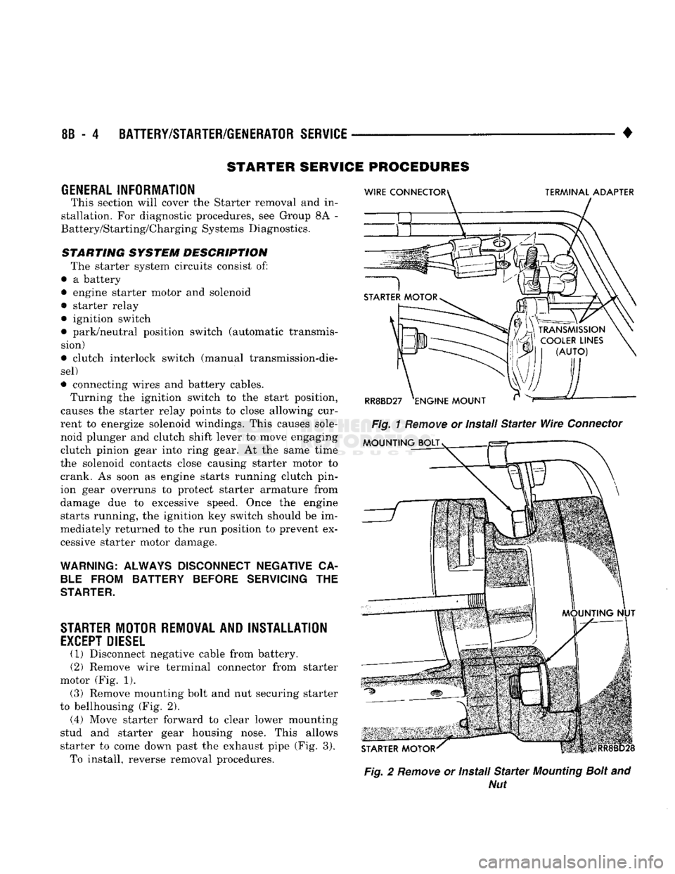
motor (Fig. 1). (3) Remove mounting bolt and nut securing starter
to bellhousing (Fig. 2).
(.4) Move starter forward to clear lower mounting
stud and starter gear housing nose. This allows
starter to come down past the exhaust pipe (Fig. 3). To install, reverse removal procedures.
Fig.
2
Remove
or Install
Starter
Mounting
Bolt
and
Nut
Page 362 of 1502
*
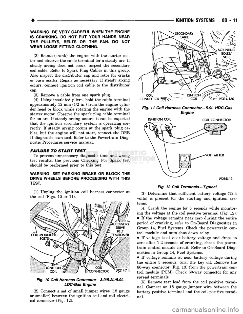
(1) Unplug the ignition coil harness connector at
the coil (Figs. 10 or 11).
Fig.
10
Coil
Harness
Connector—3.9/5.2L/5.9L
LDC-Gas
Engine
(2) Connect a set of small jumper wires (18 gauge
or smaller) between the ignition coil and coil electri
cal connector (Fig. 12).
IGNITION
SYSTEMS
80 - 11
Fig.
11
Coil
Harness
Connector—5.9L
HDC-Gas
Engine
IGNITION
COIL COIL CONNECTOR
J928D-13
Fig.
12
Coil
Terminals—Typical (3) Determine that sufficient battery voltage (12.4
volts) is present for the starting and ignition sys
tems.
(4) Crank the engine for 5 seconds while monitor
ing the voltage at the coil positive terminal (Fig. 12):
• If the voltage remains near zero during the entire
period of cranking, refer to On-Board Diagnostics in Group 14, Fuel Systems. Check the powertrain con
trol module and auto shut down relay.
• If voltage is at near battery voltage and drops to
zero after 1-2 seconds of cranking, check the power-
train control module circuit. Refer to On-Board Diag nostics in Group 14, Fuel Systems.
• If voltage remains at near battery voltage during
the entire 5 seconds, turn the key off. Remove the 60-way connector (Fig. 13) from the powertrain con
trol module (PCM). Check 60-way connector for any spread terminals.
(5) Remove test lead from the coil positive termi
nal.
Connect an 18 gauge jumper wire between the
battery positive terminal and the coil positive termi
nal.
WARNING: BE VERY CAREFUL WHEN THE ENGINE
IS
CRANKING.
DO NOT PUT
YOUR HANDS NEAR
THE PULLEYS, BELTS
OR THE FAN. DO NOT
WEAR LOOSE
FITTING
CLOTHING.
(2) Rotate (crank) the engine with the starter mo
tor and observe the cable terminal for a steady arc. If steady arcing does not occur, inspect the secondary
coil cable. Refer to Spark Plug Cables in this group.
Also inspect the distributor cap and rotor for cracks
or burn marks. Repair as necessary. If steady arcing occurs, connect ignition coil cable to the distributor
cap.
(3) Remove a cable from one spark plug.
(4) Using insulated pliers, hold the cable terminal
approximately 12 mm (1/2 in.) from the engine cylin
der head or block while rotating the engine with the starter motor. Observe the spark plug cable terminal
for an arc. If steady arcing occurs, it can be expected
that the ignition secondary system is" operating cor rectly. If steady arcing occurs at the spark plug ca
bles,
but the engine will not start, connect the DRB II diagnostic scan tool. Refer to the Powertrain Diag
nostic Procedures service manual.
FAILURE
TO START TEST To prevent unnecessary diagnostic time and wrong
test results, the previous Checking For Spark test should be performed prior to this test.
WARNING: SET PARKING BRAKE
OR
BLOCK
THE
DRIVE WHEELS BEFORE PROCEEDING
WITH
THIS
TEST.
Page 376 of 1502
IGNITION
SYSTEMS
80 - 25
IGNITION
SWITCH
INDEX
General
Information
page
. . 25
GENERAL
INFORMATION
The ignition switch is located in the steering col
umn. The Key-In-Switch and Halo Light are integral
with the ignition switch. Refer to Group 8M for Key- In-Switch and Halo Light diagnosis.
IGNITION
SWITCH
AND
KEY
CYLINDER
SERVICE
REMOVAL
(1) Disconnect negative battery cable.
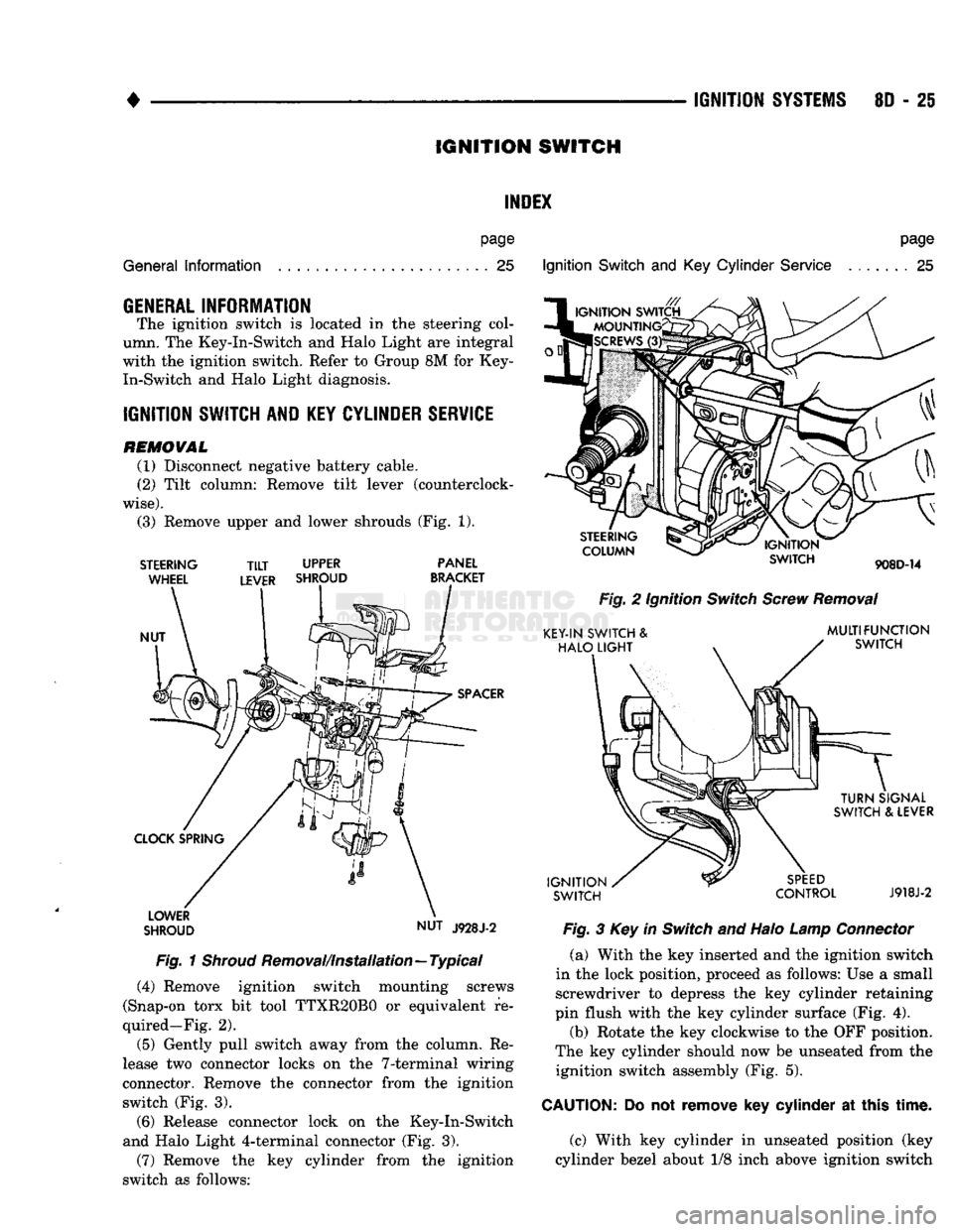
(2) Tilt column: Remove tilt lever (counterclock
wise).
(3) Remove upper and lower shrouds (Fig. 1).
STEERING
WHEEL
NUT
TILT
UPPER
LEVER SHROUD PANEL
BRACKET
SPACER
CLOCK SPRING LOWER
SHROUD NUT
J928J-2
Fig.
1
Shroud
Removal/Installation—Typical (4) Remove ignition switch mounting screws
(Snap-on torx bit tool TTXR20B0 or equivalent re
quired—Fig. 2).
(5) Gently pull switch away from the column. Re
lease two connector locks on the 7-terminal wiring
connector. Remove the connector from the ignition switch (Fig. 3).
(6) Release connector lock on the Key-In-Switch
and Halo Light 4-terminal connector (Fig. 3).
(7) Remove the key cylinder from the ignition
switch as follows:
Ignition
Switch
and Key
Cylinder
Service
page
. . 25
STEERING
COLUMN
IGNITION
SWITCH
908D-14
Fig.
2 Ignition
Switch
Screw
Removal
KEY-IN SWITCH &
HALO
LIGHT
MULTIFUNCTION
SWITCH
IGNITION
SWITCH
TURN
SIGNAL
SWITCH & LEVER
SPEED
CONTROL
J918J-2
Fig.
3 Key in
Switch
and Halo
Lamp
Connector
(a) With the key inserted and the ignition switch
in the lock position, proceed as follows: Use a small screwdriver to depress the key cylinder retaining
pin flush with the key cylinder surface (Fig. 4).
(b) Rotate the key clockwise to the OFF position.
The key cylinder should now be unseated from the ignition switch assembly (Fig. 5).
CAUTION:
Do not
remove
key
cylinder
at
this
time.
(c) With key cylinder in unseated position (key
cylinder bezel about 1/8 inch above ignition switch
Page 377 of 1502
8D
- 28
IGNITION
SYSTEMS
SMALL
SCREWDRIVER
KEY
CYLINDER
RETAINING
PIN
KEY
CYLINDER
RETAINING
PIN
IGNITION SWITCH
908D-15
Fig.
4 Key Cylinder Retaining Pin
KEY
CYLINDER
BEZEL
j
HALO
LIGHT
^
RING
908D-16
Fig.
5 Unseated Key Cylinder
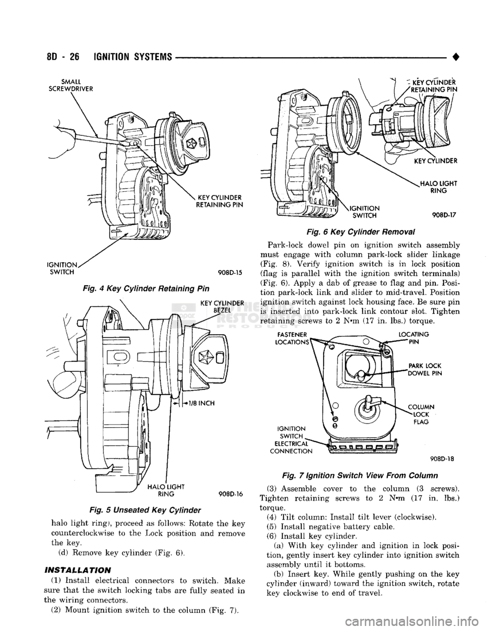
halo light ring), proceed as follows: Rotate the key
counterclockwise to the Lock position and remove
the key. (d) Remove key cylinder (Fig. 6).
INSTALLATION
(1) Install electrical connectors to switch. Make
sure that the switch locking tabs are fully seated in
the wiring connectors. (2) Mount ignition switch to the column (Fig. 7).
i-i-ii
\IGNITION
SWITCH HALO
LIGHT
RING
908D-17
Fig.
6 Key Cylinder
Removal
Park-lock dowel pin on ignition switch assembly
must engage with column park-lock slider linkage (Fig. 8). Verify ignition switch is in lock position
(flag is parallel with the ignition switch terminals)
(Fig. 6). Apply a dab of grease to flag and pin. Posi
tion park-lock link and slider to mid-travel. Position ignition switch against lock housing face. Be sure pin
is inserted into park-lock link contour slot. Tighten
retaining screws to 2 N#m (17 in. lbs.) torque.
FASTENER
LOCATIONS LOCATING
PIN
PARK
LOCK
'DOWEL
PIN
IGNITION SWITCH
ELECTRICAL
CONNECTION COLUMN
LOCK
FLAG 908D-18
Fig.
7 Ignition
Switch
View From
Column
(3) Assemble cover to the column (3 screws).
Tighten retaining screws to 2 N»m (17 in. lbs.)
torque.
(4) Tilt column: Install tilt lever (clockwise).
(5) Install negative battery cable.
(6) Install key cylinder. (a) With key cylinder and ignition in lock posi
tion, gently insert key cylinder into ignition switch assembly until it bottoms.
(b) Insert key. While gently pushing on the key
cylinder (inward) toward the ignition switch, rotate key clockwise to end of travel.
Page 384 of 1502
•
INSTRUMENT PANEL
AND
GAUGES
8E - 3
MALFUNCTION INDICATOR (CHECK ENGINE)
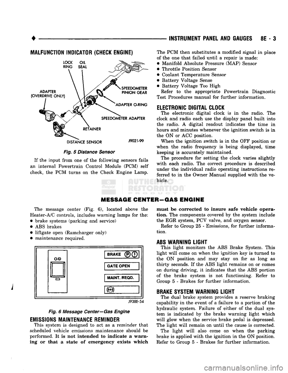
Fig.
5
Distance Sensor
If
the
input from
one of the
following sensors fails
an internal Powertrain Control Module
(PCM)
self
check,
the PCM
turns
on the
Check Engine Lamp. The
PCM
then substitutes
a
modified signal
in
place
of
the one
that failed until
a
repair
is
made:
• Manifold Absolute Pressure (MAP) Sensor
• Throttle Position Sensor
• Coolant Temperature Sensor
• Battery Voltage Sense
• Battery Voltage
Too
High
Refer
to the
appropriate Powertrain Diagnostic
Test Procedures manual
for
further information.
ELECTRONIC DIGITAL CLOCK
The electronic digital clock
is in the
radio.
The
clock
and
radio each
use the
display panel built into
the radio.
A
digital readout indicates
the
time
in
hours
and
minutes whenever
the
ignition switch
is in
the
ON or ACC
position. When
the
ignition switch
is in the OFF
position
or
when
the
radio frequency
is
being displayed, time keeping
is
accurately maintained. The procedure
for
setting
the
clock varies slightly
with each radio.
The
correct procedure
is
described under
the
individual radio operating instructions
re
ferred
to in the
Owner Manual supplied with
the ve
hicle.
MESSAGE CENTER—GAS ENGINE
The message center
(Fig. 6),
located above
the
Heater-A/C controls, includes warning lamps
for the:
• brake systems (parking
and
service)
•
ABS
brakes • liftgate open (Ramcharger only)
• maintenance required.
O/D
BRAKE
(P)(7
GATE OPEN
MAINT
REQD.
J938E-54
Fig.
6
Message Center—Gas Engine
EMISSIONS
MAINTENANCE REMINDER
This system
is
designed
to act as a
reminder that
scheduled vehicle emissions maintenance should
be
performed.
It is not
intended
to
indicate
a
warn
ing
or
that
a
state
of
emergency exists which must
be
corrected
to
insure safe vehicle opera
tion.
The
components covered
by the
system include
the
EGR
system,
PCV
valve,
and
oxygen sensor. Refer
to
Group
25 -
Emissions,
for
further informa
tion.
ABS
WARNING
LIGHT
This light monitors
the ABS
Brake System. This
light will come
on
when
the
ignition
key is
turned
to
the
ON
position
and may
stay
on for as
long
as
thirty seconds.
If the ABS
light remains
on or
comes on during driving,
it
indicates that
the ABS
portion
of
the
brake system
is not
functioning. Refer
to
Group
5 -
Brakes
for
further information.
BRAKE
SYSTEM WARNING
LIGHT
The dual brake system provides
a
reserve braking
capability
in the
event
of a
failure
to a
portion
of the
hydraulic system. Failure
of
either
of the
dual sys
tem
is
indicated
by the
brake warning light which
will glow when
the
service brake pedal
is
depressed.
The light will remain
on
until
the
cause
is
corrected. The light will also come
on
when
the
parking
brake
is
applied with
the
ignition
in the ON
position.
Refer
to
Group
5 -
Brakes
for
further information.
Page 389 of 1502
8E
- 8 INSTRUMENT PANEL AND GAUGES
•
BRAKE
WARNING
LAMP
SWITCH TO BRAKE
WARNING LAMP
PR!
451
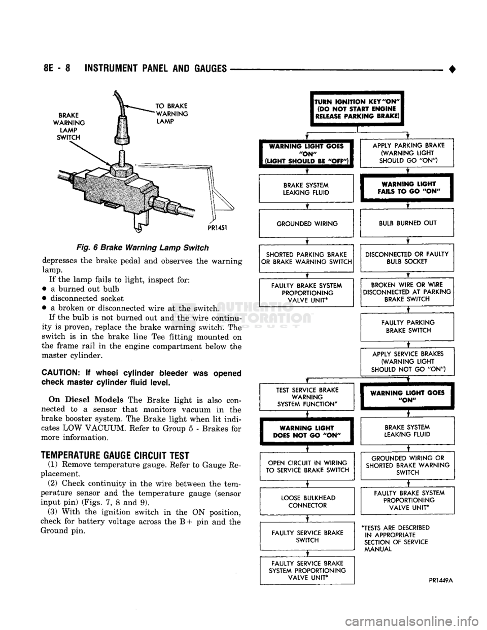
Fig.
6
Brake Warning
Lamp
Switch
depresses
the
brake pedal
and
observes
the
warning
lamp.
If
the
lamp fails
to
light, inspect
for:
•
a
burned
out
bulb
• disconnected socket
•
a
broken
or
disconnected wire
at the
switch. If
the
bulb
is not
burned
out and the
wire continu
ity
is
proven, replace
the
brake warning switch.
The
switch
is in the
brake line
Tee
fitting mounted
on
the frame rail
in the
engine compartment below
the
master cylinder.
CAUTION:
If
wheel cylinder bleeder
was
opened
check
master cylinder fluid level.
On Diesel Models
The
Brake light
is
also con
nected
to a
sensor that monitors vacuum
in the
brake booster system.
The
Brake light when
lit
indi cates
LOW
VACUUM. Refer
to
Group
5 -
Brakes
for
more information.
TEMPERATURE
GAUGE CIRCUIT TEST
(1) Remove temperature gauge. Refer
to
Gauge
Re
placement. (2) Check continuity
in the
wire between
the
tem
perature sensor
and the
temperature gauge (sensor
input
pin)
(Figs.
7, 8 and 9).
(3) With
the
ignition switch
in the ON
position,
check
for
battery voltage across
the B + pin and the
Ground
pin.
(TURN
IGNITION
KEY
"ON"
(DO
NOT
START
ENGINE
I
RELEASE
PARKING
BRAKE)
I
I
[
WARNING
LIGHT
GOES
I
"ON"
I
1
(LIGHT
SHOULD
BE
"OFF")!
X
APPLY PARKING BRAKE (WARNING
LIGHT
SHOULD
GO "ON")
BRAKE
SYSTEM
LEAKING FLUID
X
WARNING
LIGHT
FAILS
TO GO "ON" GROUNDED WIRING
BULB
BURNED
OUT
SHORTED PARKING BRAKE
OR BRAKE WARNING SWITCH
X
DISCONNECTED
OR
FAULTY
BULB
SOCKET
FAULTY BRAKE SYSTEM PROPORTIONING VALVE
UNIT*
BROKEN
WIRE
OR
WIRE
DISCONNECTED
AT
PARKING
BRAKE
SWITCH
X
FAULTY PARKING
BRAKE
SWITCH
X
APPLY SERVICE BRAKES
(WARNING
LIGHT
SHOULD
NOT GO "ON")
JZ
X
TEST SERVICE BRAKE WARNING
SYSTEM FUNCTION*
X
WARNING
LIGHT
GOES
"ON"
WARNING
LIGHT
DOES
NOT GO "ON"
BRAKE
SYSTEM
LEAKING FLUID
OPEN CIRCUIT
IN
WIRING
TO SERVICE BRAKE SWITCH
X
GROUNDED WIRING
OR
SHORTED BRAKE WARNING SWITCH
LOOSE
BULKHEAD CONNECTOR
X
FAULTY BRAKE SYSTEM
PROPORTIONING VALVE
UNIT*
FAULTY SERVICE BRAKE SWITCH
X
•TESTS
ARE
DESCRIBED
IN APPROPRIATE
SECTION
OF
SERVICE MANUAL
FAULTY SERVICE BRAKE
SYSTEM PROPORTIONING VALVE
UNIT*
PR1449A