steering DODGE VIPER 2010 ZB II / 2.G User Guide
[x] Cancel search | Manufacturer: DODGE, Model Year: 2010, Model line: VIPER, Model: DODGE VIPER 2010 ZB II / 2.GPages: 80, PDF Size: 8.08 MB
Page 3 of 80
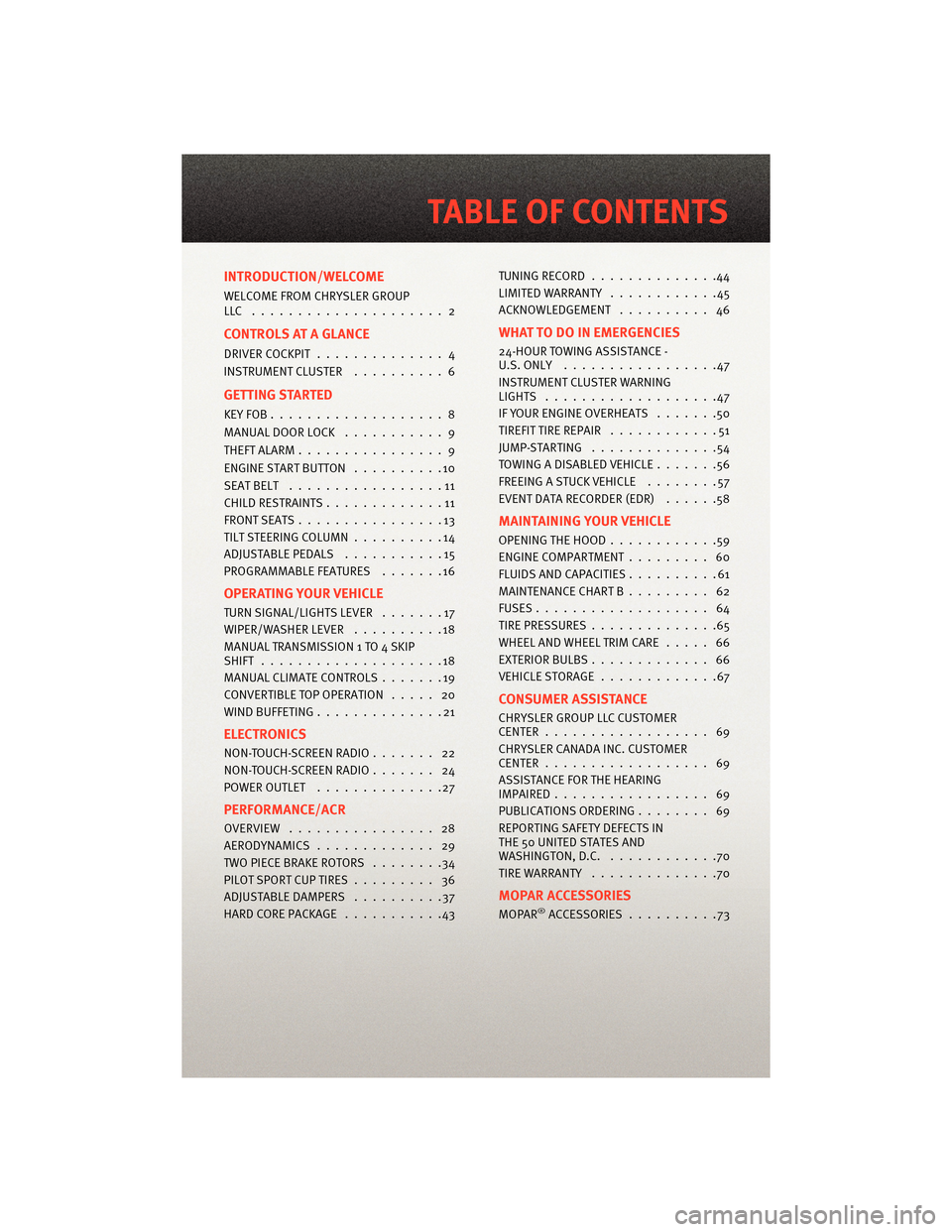
INTRODUCTION/WELCOME
WELCOME FROM CHRYSLER GROUP
LLC ..................... 2
CONTROLS AT A GLANCE
DRIVER COCKPIT.............. 4
INSTRUMENT CLUSTER ..........6
GETTING STARTED
KEYFOB...................8
MANUAL DOOR LOCK........... 9
THEFT ALARM ................ 9
ENGINE START BUTTON ..........10
SEATBELT .................11
CHILD RESTRAINTS .............11
FRONTSEATS................13
TILT STEERING COLUMN ..........14
ADJUSTABLEPEDALS ...........15
PROGRAMMABLEFEATURES .......16
OPERATING YOUR VEHICLE
TURN SIGNAL/LIGHTS LEVER .......17
WIPER/WASHER LEVER ..........18
MANUAL TRANSMISS ION 1 TO 4 SKIP
SHIFT ....................18
MANUAL CLIMATE CONTROLS .......19
CONVERTIBLE TOP OPERATION ..... 20
WIND BUFFETING ..............21
ELECTRONICS
NON-TOUCH-SCREENRADIO....... 22
NON-TOUCH-SCREENRADIO....... 24
POWER OUTLET..............27
PERFORMANCE/ACR
OVERVIEW ................ 28
AERODYNAMICS............. 29
TWO PIECE BRAKE ROTORS ........34
PILOTSPORTCUPTIRES......... 36
ADJUSTABLE DAMPERS ..........37
HARDCOREPACKAGE ...........43 TUNINGRECORD ..............44
LIMITED WARRANTY
............45
ACKNOWLEDGEMENT .......... 46
WHAT TO DO IN EMERGENCIES
24-HOUR TOWINGASSISTANCE -
U.S. ONLY .................47
INSTRUMENT CLUSTER WARNING
LIGHTS ...................47
IF YOUR ENGINE OVERHEATS .......50
TIREFIT TIRE REPAIR ............51
JUMP-STARTING ..............54
TOWINGADISABLEDVEHICLE.......56
FREEING A STUCK VEHICLE ........57
EVENT DATA RECORDER (EDR) ......58
MAINTAINING YOUR VEHICLE
OPENING THE HOOD............59
ENGINE COMPARTMENT ......... 60
FLUIDS AND CAPACITIES ..........61
MAINTENANCE CHART B ......... 62
FUSES................... 64
TIREPRESSURES..............65
WHEEL AND WHEEL TRIM CARE ..... 66
EXTERIOR BULBS ............. 66
VEHICLESTORAGE .............67
CONSUMER ASSISTANCE
CHRYSLER GROUP LLC CUSTOMER
CENTER.................. 69
CHRYSLER CANADA INC. CUSTOMER
CENTER.................. 69
ASSISTANCE F OR THE HEARING
IMPAIRED................. 69
PUBLICATIONS ORDERING ........ 69
REPORTING SAFETY DEFECTS IN
THE 50 UNITED STATES AND
WASHINGTON, D.C. ............70
TIRE WARRANTY ..............70
MOPAR ACCESSORIES
MOPAR®ACCESSORIES..........73
TABLE OF CONTENTS
Page 16 of 80
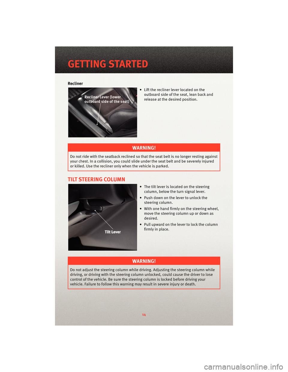
Recliner
• Lift the recliner lever located on theoutboard side of the seat, lean back and
release at the desired position.
WARNING!
Do not ride with the seatback reclined so that the seat belt is no longer resting against
your chest. In a collision, you could slide under the seat belt and be severely injured
or killed. Use the recliner only when the vehicle is parked.
TILT STEERING COLUMN
• The tilt lever is located on the steeringcolumn, below the turn signal lever.
• Push down on the lever to unlock the steering column.
• With one hand firmly on the steering wheel, move the steering column up or down as
desired.
• Pull upward on the lever to lock the column firmly in place.
WARNING!
Do not adjust the steering column while driving. Adjusting the steering column while
driving, or driving with the steering column un locked, could cause the driver to lose
control of the vehicle. Be sure the steerin g column is locked before driving your
vehicle. Failure to follow this warning may result in severe injury or death.
GETTING STARTED
14
Page 17 of 80
ADJUSTABLE PEDALS
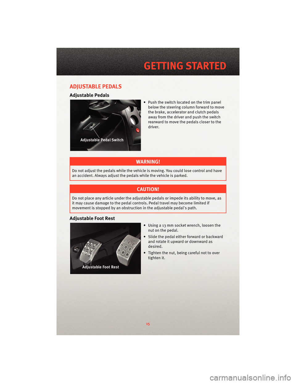
Adjustable Pedals
• Push the switch located on the trim panelbelow the steering column forward to move
the brake, accelerator and clutch pedals
away from the driver and push the switch
rearward to move the pedals closer to the
driver.
WARNING!
Do not adjust the pedals while the vehicle is moving. You could lose control and have
an accident. Always adjust the pedals while the vehicle is parked.
CAUTION!
Do not place any article under the adjustable pedals or impede its ability to move, as
it may cause damage to the pedal controls. Pedal travel may become limited if
movement is stopped by an obstruction in the adjustable pedal's path.
Adjustable Foot Rest
• Using a 13 mm socket wrench, loosen the
nut on the pedal.
• Slide the pedal either forward or backward and rotate it upward or downward as
desired.
• Tighten the nut, being careful not to over tighten it.
15
GETTING STARTED
Page 38 of 80
CAUTION!
Do not come to a complete stop when the system is hot and leave your foot on the
pedal. Pad material will immediately transfer to the rotor causing a vibration during
future use.
• After the final stop, drive as much as possible without using the brakes to cool off the system. Ideally, the brakes should be allowed to cool to ambient temperature
before using them again.
• After the first break in cycle, the brakes will still not be operating at optimum capacity. A second or third heat cycle is typically necessary before the brakes start
to work optimally. This will occur during everyday use.
Care and Maintenance
• Your brake calipers have a painted finish. Immedi ately clean off any spilled brake
fluid, wiping it off with a soft, clean terry-cloth towel.
• Do not use any harsh chemicals when cleaning your calipers. Wash your calipers with soap and rinse with water.
• Do not use any harsh chemicals when cleaning your rotor hats (the anodized center part of the rotor assembly). Wash your rotor hats with soap and rinse with water.
• Breaking-in rotors and pads is critical to the optimum performance of your new brakes. When breaking-in new parts, you are not only heat-cycling the pads, you are
also depositing a layer of pad material onto the rotor face. If not broken-in properly, an
uneven layer of pad material will be deposited onto the rotor, causing vibration.
• If you experience brake pedal pulsation, steering vibration, or repeatable brake noise, perform the break-in procedure again as soon as possible. This will re-condition the
rotor surface and remove irregular brake pad deposits. If concerns continue, please
visit y our local dealer fo r further diagnosis.
PILOT SPORT CUP TIRES
• Your Viper ACR comes equipped with Michelin Pilot Sport Cup competition oriented
tires that are DOT approved for street use. The Pilot Sport Cup tire uses a special tread
and compound which provides considerably more dry grip than normal street tires.
• Due to the special tread and compound of your Pilot Sport Cup Tires, the minimum tread depth can be reached earlier dependin g on your driving style, resulting in
reduced tire life. The special Pilot S port Cup tread and compound may lead to
performance degradation in cold climates, heavy rain or in conditions with standing
water.
WARNING!
Use extreme caution and drive slowly in wet situations to reduce the risk of
hydroplaning. Avoid driving in any conditions of heavy rain or standing water. These
conditions can cause loss of control or accident.
PERFORMANCE/ACR
36
Page 54 of 80
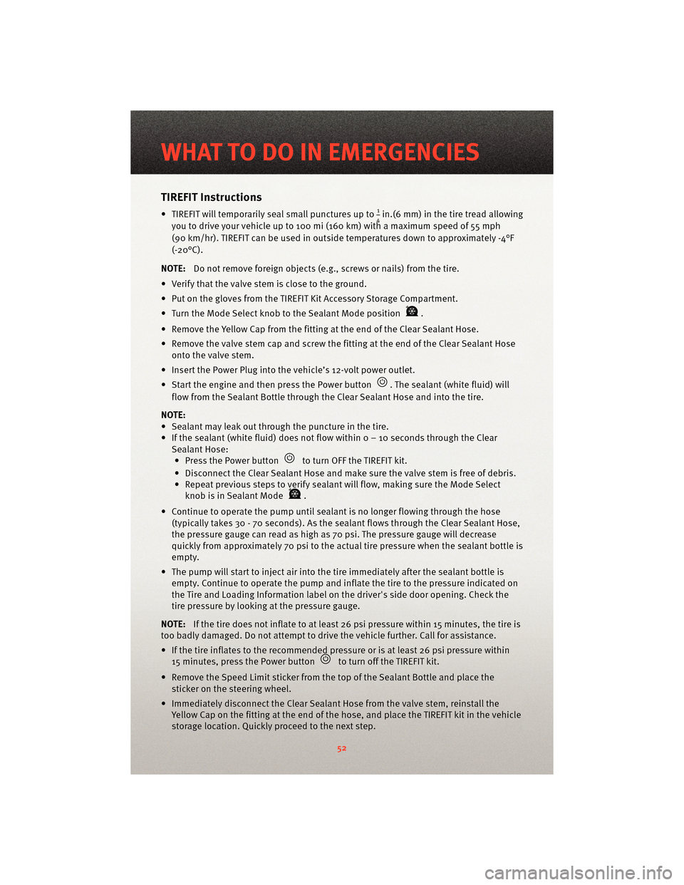
TIREFIT Instructions
• TIREFIT will temporarily seal small punctures up to14in.(6 mm) in the tire tread allowing
you to drive your vehicle up to 100 mi (160 km) with a maximum speed of 55 mph
(90 km/hr). TIREFIT can be used in outside temperatures down to approximately -4°F
(-20°C).
NOTE: Do not remove foreign objects (e.g., screws or nails) from the tire.
• Verify that the valve stem is close to the ground.
• Put on the gloves from the TIREFIT Kit Accessory Storage Compartment.
• Turn the Mode Select knob to the Sealant Mode position
.
• Remove the Yellow Cap from the fitting at the end of the Clear Sealant Hose.
• Remove the valve stem cap and screw the fitting at the end of the Clear Sealant Hose onto the valve stem.
• Insert the Power Plug into the vehicle’s 12-volt power outlet.
• Start the engine and then press the Power button
. The sealant (white fluid) will
flow from the Sealant Bottle through the Clear Sealant Hose and into the tire.
NOTE:
• Sealant may leak out through the puncture in the tire.
• If the sealant (white fluid) does not flow withi n0–10secondsthrough the Clear
Sealant Hose: • Press the Power button
to turn OFF the TIREFIT kit.
• Disconnect the Clear Sealant Hose and make sure the valve stem is free of debris.
• Repeat previous steps to verify sealant will flow, making sure the Mode Select knob is in Sealant Mode
.
• Continue to operate the pump until seal ant is no longer flowing through the hose
(typically takes 30 - 70 seconds). As the sealant flows through the Clear Sealant Hose,
the pressure gauge can read as high as 70 psi. The pressure gauge will decrease
quickly from approximately 70 psi to the actual tire pressure when the sealant bottle is
empty.
• The pump will start to inject air into the tire immediately after the sealant bottle is
empty. Continue to operate the pump and inflate the tire to the pressure indicated on
the Tire and Loading Information label on the driver's side door opening. Check the
tire pressure by looking at the pressure gauge.
NOTE: If the tire does not inflate to at least 26 psi pressure within 15 minutes, the tire is
too badly damaged. Do not attempt to drive the vehicle further. Call for assistance.
• If the tire inflates to the recommended pressure or is at least 26 psi pressure within 15 minutes, press the Power button
to turn off the TIREFIT kit.
• Remove the Speed Limit sticker from the top of the Sealant Bottle and place the sticker on the steering wheel.
• Immediately disconnect the Clear Sealant Ho se from the valve stem, reinstall the
Yellow Cap on the fitting at the end of the hose, and place the TIREFIT kit in the vehicle
storage location. Quickly proceed to the next step.
WHAT TO DO IN EMERGENCIES
52
Page 59 of 80
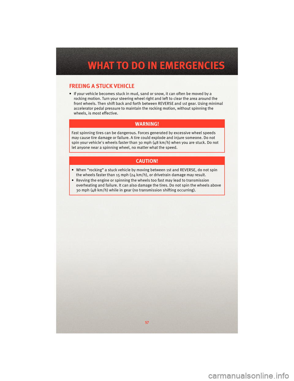
FREEING A STUCK VEHICLE
• If your vehicle becomes stuck in mud, sand or snow, it can often be moved by arocking motion. Turn your steering wheel right and left to clear the area around the
front wheels. Then shift back and forth between REVERSE and 1st gear. Using minimal
accelerator pedal pressure to maintain the rocking motion, without spinning the
wheels, is most effective.
WARNING!
Fast spinning tires can be dangerous. Forces generated by excessive wheel speeds
may cause tire damage or failure. A tire could explode and injure someone. Do not
spin your vehicle's wheels faster than 30 mph (48 km/h) when you are stuck. Do not
let anyone near a spinning wheel, no matter what the speed.
CAUTION!
• When “rocking” a stuck vehicle by moving between 1st and REVERSE, do not spin the wheels faster than 15 mph (24 km/h), or drivetrain damage may result.
• Revving the engine or s pinning the wheels too fast ma y lead to transmission
overheating and failure. It can also damage the tires. Do not spin the wheels above
30 mph (48 km/h) while in gear (no transmission shifting occurring).
57
WHAT TO DO IN EMERGENCIES
Page 63 of 80
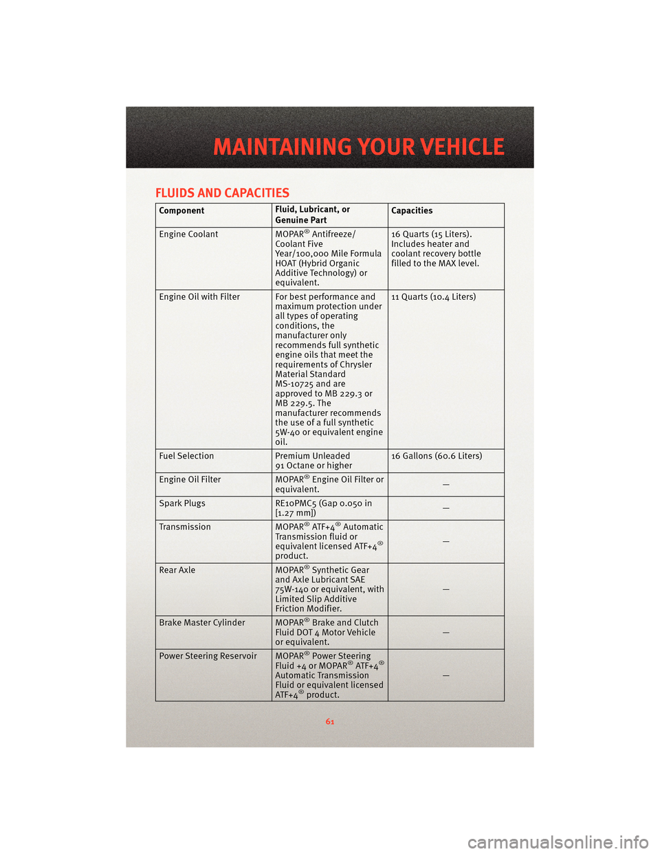
FLUIDS AND CAPACITIES
ComponentFluid, Lubricant, or
Genuine PartCapacities
Engine Coolant MOPAR
®Antifreeze/
Coolant Five
Year/100,000 Mile Formula
HOAT (Hybrid Organic
Additive Technology) or
equivalent. 16 Quarts (15 Liters).
Includes heater and
coolant recovery bottle
filled to the MAX level.
Engine Oil with Filter For best performance and maximum protection under
all types of operating
conditions, the
manufacturer only
recommends full synthetic
engine oils that meet the
requirements of Chrysler
Material Standard
MS-10725 and are
approved to MB 229.3 or
MB 229.5. The
manufacturer recommends
the use of a full synthetic
5W-40 or equivalent engine
oil.11 Quarts (10.4 Liters)
Fuel Selection Premium Unleaded
91 Octane or higher 16 Gallons (60.6 Liters)
Engine Oil Filter MOPAR
®Engine Oil Filter or
equivalent. —
Spark Plugs RE10PMC5 (Gap 0.050 in
[1.27 mm]) —
Transmission MOPAR
®ATF+4®Automatic
Transmission fluid or
equivalent licensed ATF+4
®
product. —
Rear Axle MOPAR®Synthetic Gear
and Axle Lubricant SAE
75W-140 or equivalent, with
Limited Slip Additive
Friction Modifier. —
Brake Master Cylinder MOPAR
®Brake and Clutch
Fluid DOT 4 Motor Vehicle
or equivalent. —
Power Steering Reservoir MOPAR
®Power Steering
Fluid +4 or MOPAR®ATF+4®
Automatic Tr ansmission
Fluid or equivalent licensed
ATF+4
®product. —
61
MAINTAINING YOUR VEHICLE
Page 67 of 80
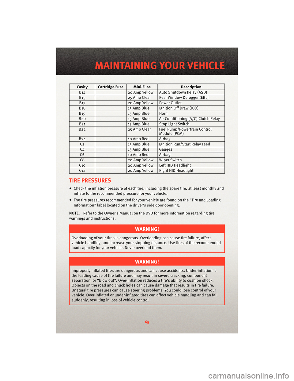
Cavity Cartridge Fuse Mini-FuseDescription
B14 20 Amp Yellow Auto Shutdown Relay (ASD)
B15 25 Amp Clear Rear Window Defogger (EBL)
B17 20 Amp Yellow Power Outlet
B18 15 Amp Blue Ignition Off Draw (IOD)
B19 15 Amp Blue Horn
B20 15 Amp Blue Air Conditioning (A/C) Clutch Relay
B21 15 Amp Blue Stop Light Switch
B22 25 Amp Clear Fuel Pump/Powertrain Control
Module (PCM)
B24 10 Amp Red Airbag
C2 15 Amp Blue Ignition Run/Start Relay Feed
C4 15 Amp Blue Gauges
C6 10 Amp Red Airbag
C8 20 Amp Yellow Wiper Switch
C10 20 Amp Yellow Left HID Headlight
C12 20 Amp Yellow Right HID Headlight
TIRE PRESSURES
• Check the inflation pressure of each tire, including the spare tire, at least monthly and
inflate to the recommended pressure for your vehicle.
• The tire pressures recommended for your vehicle are found on the “Tire and Loading Information” label located on the driver’s side door opening.
NOTE: Refer to the Owner's Manual on the DVD f or more information regarding tire
warnings and instructions.
WARNING!
Overloading of your tires is dangerous. Ov erloading can causetire failure, affect
vehicle handling, and increase your stopping distance. Use tires of the recommended
load capacity for your vehicle. Never overload them.
WARNING!
Improperly inflated tires are dangerous and can cause accidents. Under-inflation is
the leading cause of tire failure and may result in severe cracking, component
separation, or “blow out”. Over-inflation r educes a tire’s ability to cushion shock.
Objects on the road and chuck holes can cause damage that results in tire failure.
Unequal tire pressures can cause steering problems. You could lose control of your
vehicle. Over-inflated or under-inflated ti res can affect vehicle handling and can fail
suddenly, resulting in loss of vehicle control.
65
MAINTAINING YOUR VEHICLE