wheel DODGE VIPER 2010 ZB II / 2.G User Guide
[x] Cancel search | Manufacturer: DODGE, Model Year: 2010, Model line: VIPER, Model: DODGE VIPER 2010 ZB II / 2.GPages: 80, PDF Size: 8.08 MB
Page 3 of 80
INTRODUCTION/WELCOME
WELCOME FROM CHRYSLER GROUP
LLC ..................... 2
CONTROLS AT A GLANCE
DRIVER COCKPIT.............. 4
INSTRUMENT CLUSTER ..........6
GETTING STARTED
KEYFOB...................8
MANUAL DOOR LOCK........... 9
THEFT ALARM ................ 9
ENGINE START BUTTON ..........10
SEATBELT .................11
CHILD RESTRAINTS .............11
FRONTSEATS................13
TILT STEERING COLUMN ..........14
ADJUSTABLEPEDALS ...........15
PROGRAMMABLEFEATURES .......16
OPERATING YOUR VEHICLE
TURN SIGNAL/LIGHTS LEVER .......17
WIPER/WASHER LEVER ..........18
MANUAL TRANSMISS ION 1 TO 4 SKIP
SHIFT ....................18
MANUAL CLIMATE CONTROLS .......19
CONVERTIBLE TOP OPERATION ..... 20
WIND BUFFETING ..............21
ELECTRONICS
NON-TOUCH-SCREENRADIO....... 22
NON-TOUCH-SCREENRADIO....... 24
POWER OUTLET..............27
PERFORMANCE/ACR
OVERVIEW ................ 28
AERODYNAMICS............. 29
TWO PIECE BRAKE ROTORS ........34
PILOTSPORTCUPTIRES......... 36
ADJUSTABLE DAMPERS ..........37
HARDCOREPACKAGE ...........43 TUNINGRECORD ..............44
LIMITED WARRANTY
............45
ACKNOWLEDGEMENT .......... 46
WHAT TO DO IN EMERGENCIES
24-HOUR TOWINGASSISTANCE -
U.S. ONLY .................47
INSTRUMENT CLUSTER WARNING
LIGHTS ...................47
IF YOUR ENGINE OVERHEATS .......50
TIREFIT TIRE REPAIR ............51
JUMP-STARTING ..............54
TOWINGADISABLEDVEHICLE.......56
FREEING A STUCK VEHICLE ........57
EVENT DATA RECORDER (EDR) ......58
MAINTAINING YOUR VEHICLE
OPENING THE HOOD............59
ENGINE COMPARTMENT ......... 60
FLUIDS AND CAPACITIES ..........61
MAINTENANCE CHART B ......... 62
FUSES................... 64
TIREPRESSURES..............65
WHEEL AND WHEEL TRIM CARE ..... 66
EXTERIOR BULBS ............. 66
VEHICLESTORAGE .............67
CONSUMER ASSISTANCE
CHRYSLER GROUP LLC CUSTOMER
CENTER.................. 69
CHRYSLER CANADA INC. CUSTOMER
CENTER.................. 69
ASSISTANCE F OR THE HEARING
IMPAIRED................. 69
PUBLICATIONS ORDERING ........ 69
REPORTING SAFETY DEFECTS IN
THE 50 UNITED STATES AND
WASHINGTON, D.C. ............70
TIRE WARRANTY ..............70
MOPAR ACCESSORIES
MOPAR®ACCESSORIES..........73
TABLE OF CONTENTS
Page 16 of 80
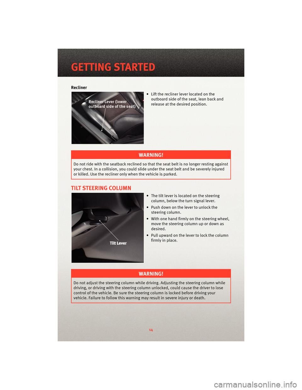
Recliner
• Lift the recliner lever located on theoutboard side of the seat, lean back and
release at the desired position.
WARNING!
Do not ride with the seatback reclined so that the seat belt is no longer resting against
your chest. In a collision, you could slide under the seat belt and be severely injured
or killed. Use the recliner only when the vehicle is parked.
TILT STEERING COLUMN
• The tilt lever is located on the steeringcolumn, below the turn signal lever.
• Push down on the lever to unlock the steering column.
• With one hand firmly on the steering wheel, move the steering column up or down as
desired.
• Pull upward on the lever to lock the column firmly in place.
WARNING!
Do not adjust the steering column while driving. Adjusting the steering column while
driving, or driving with the steering column un locked, could cause the driver to lose
control of the vehicle. Be sure the steerin g column is locked before driving your
vehicle. Failure to follow this warning may result in severe injury or death.
GETTING STARTED
14
Page 36 of 80
• The rear wing on the non two-tone ACR is molded completely with unidirectionalcarbon fiber and painted in body color. Some patterned or linear conditions may be
visible in the p ainted carbon fiber surfaces. This i s also a normal result of the carbon
fiber process.
TWO PIECE BRAKE ROTORS
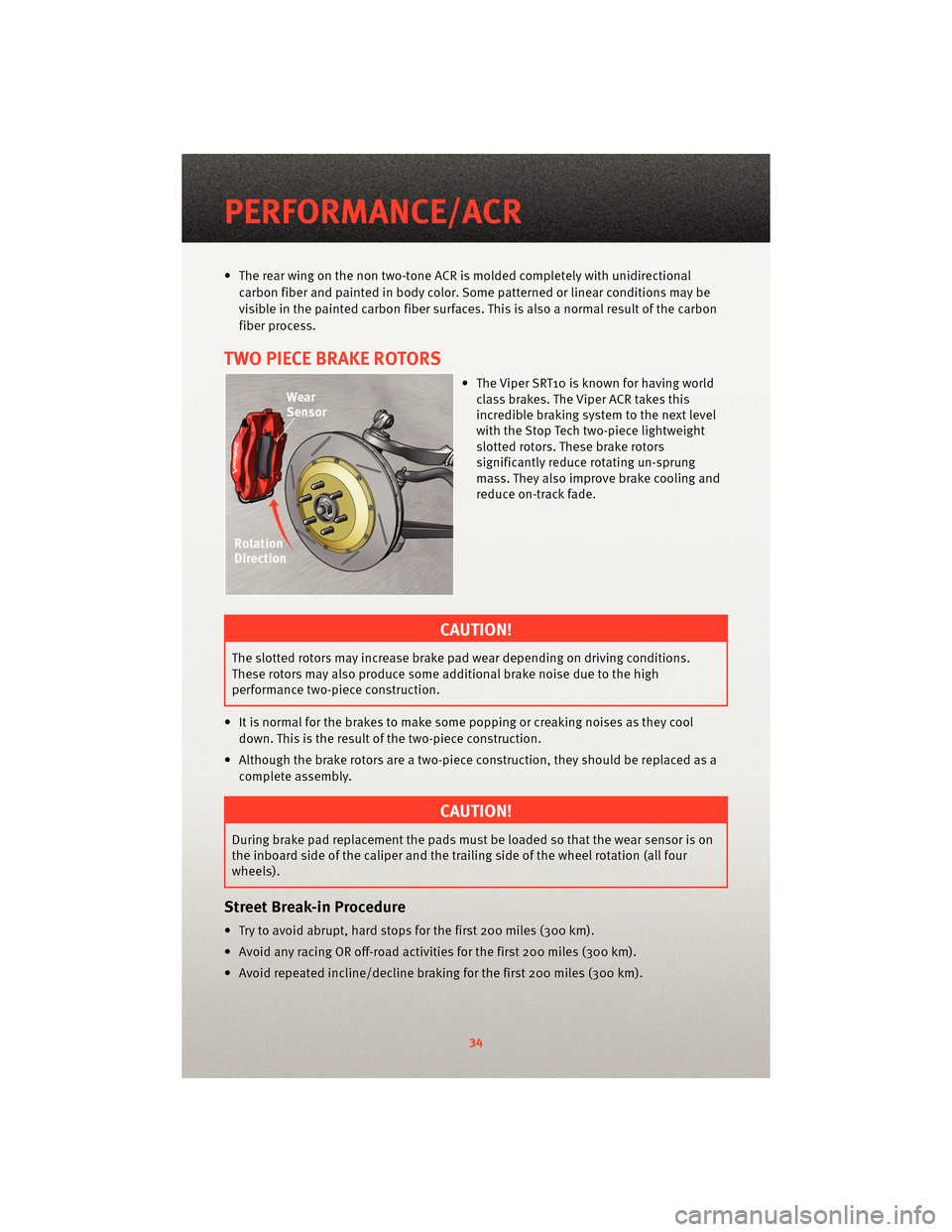
• The Viper SRT10 is known for having world class brakes . The Viper ACR takes this
incredible braking system to the next level
with the Stop Tech two-piece lightweight
slotted rotors. These brake rotors
significantly reduce rotating un-sprung
mass. They also improve brake cooling and
reduce on-track fade.
CAUTION!
The slotted rotors may increase brake pad wear depending on driving conditions.
These rotors may also produce some additional brake noise due to the high
performance two-piece construction.
• It is normal for the brakes to make some popping or creaking noises as they cool down. This is the result of the two-piece construction.
• Although the brake rotors are a two-piece construction, they should be replaced as a complete assembly.
CAUTION!
During brake pad replacement the pads must be loaded so that the wear sensor is on
the inboard side of the caliper and the trailing side of the wheel rotation (all four
wheels).
Street Break-in Procedure
• Try to avoid abrupt, hard stops for the first 200 miles (300 km).
• Avoid any racing OR off-road activities for the first 200 miles (300 km).
• Avoid repeated incline/decline braking for the first 200 miles (300 km).
PERFORMANCE/ACR
34
Page 41 of 80
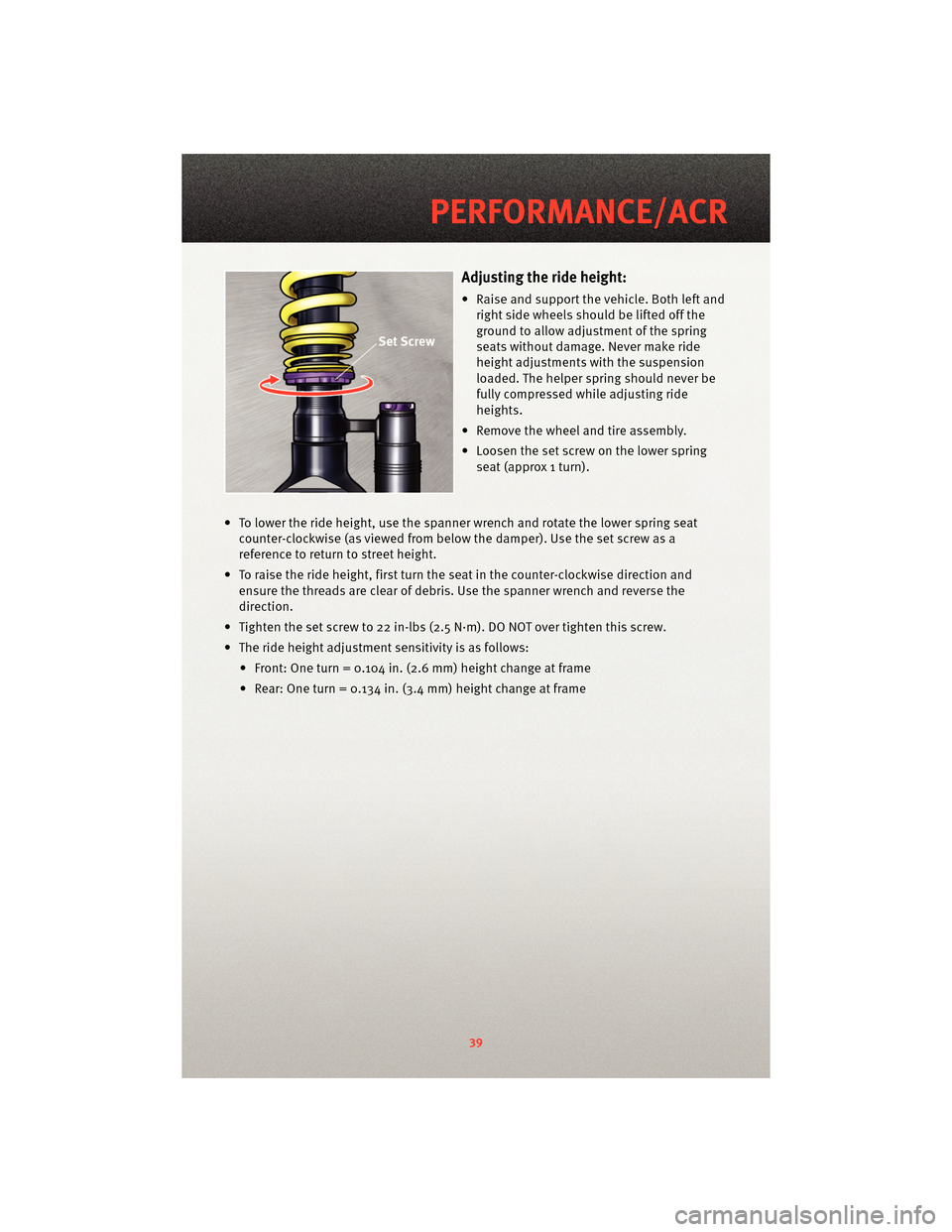
Adjusting the ride height:
• Raise and support the vehicle. Both left andright side wheels should be lifted off the
ground to allow adjustment of the spring
seats without damage. Never make ride
height adjustments with the suspension
loaded. The helper spring should never be
fully compressed while adjusting ride
heights.
• Remove the wheel and tire assembly.
• Loosen the set screw on the lower spring seat (approx 1 turn).
• To lower the ride height, use the spanner wrench and rotate the lower spring seat counter-clockwise (as viewed fr om below the damper). Use the set screw as a
reference to return to street height.
• To raise the ride height, first turn the seat in the counter-clockwise direction and ensure the threads are clear of debris. Use the spanner wrench and reverse the
direction.
• Tighten the set screw to 22 in-lbs (2.5 N·m). DO NOT over tighten this screw.
• The ride height adjustment sensitivity is as follows: • Front: One turn = 0.104 in. (2.6 mm) height change at frame
• Rear: One turn = 0.134 in. (3.4 mm) height change at frame
39
PERFORMANCE/ACR
Page 42 of 80
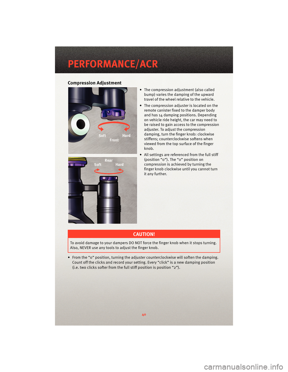
Compression Adjustment
• The compression adjustment (also calledbump) varies the damping of the upward
travel of the wheel relative to the vehicle.
• The compression adjuster is located on the remote canister fixed to the damper body
and has 14 damping positions. Depending
on vehicle ride height, the car may need to
be raised to gain access to the compression
adjuster. To adjust the compression
damping, turn the finge r knob: clockwise
stiffens; counterclockwise softens when
viewed from the top surface of the finger
knob.
• All settings are referenced from the full stiff (position “0”). The “0” position on
compression is achieved by turning the
finger knob clockwise until you cannot turn
it any further.
CAUTION!
To avoid damage to your dampers DO NOT force the finger knob when it stops turning.
Also, NEVER use any tools to adjust the finger knob.
• From the “0” position, turning the adjuster cou nterclockwise will soften the damping.
Count off the clicks and record your setting. Every “click” is a new damping position
(i.e. two clicks softer from the full stiff position is position “2”).
PERFORMANCE/ACR
40
Page 43 of 80
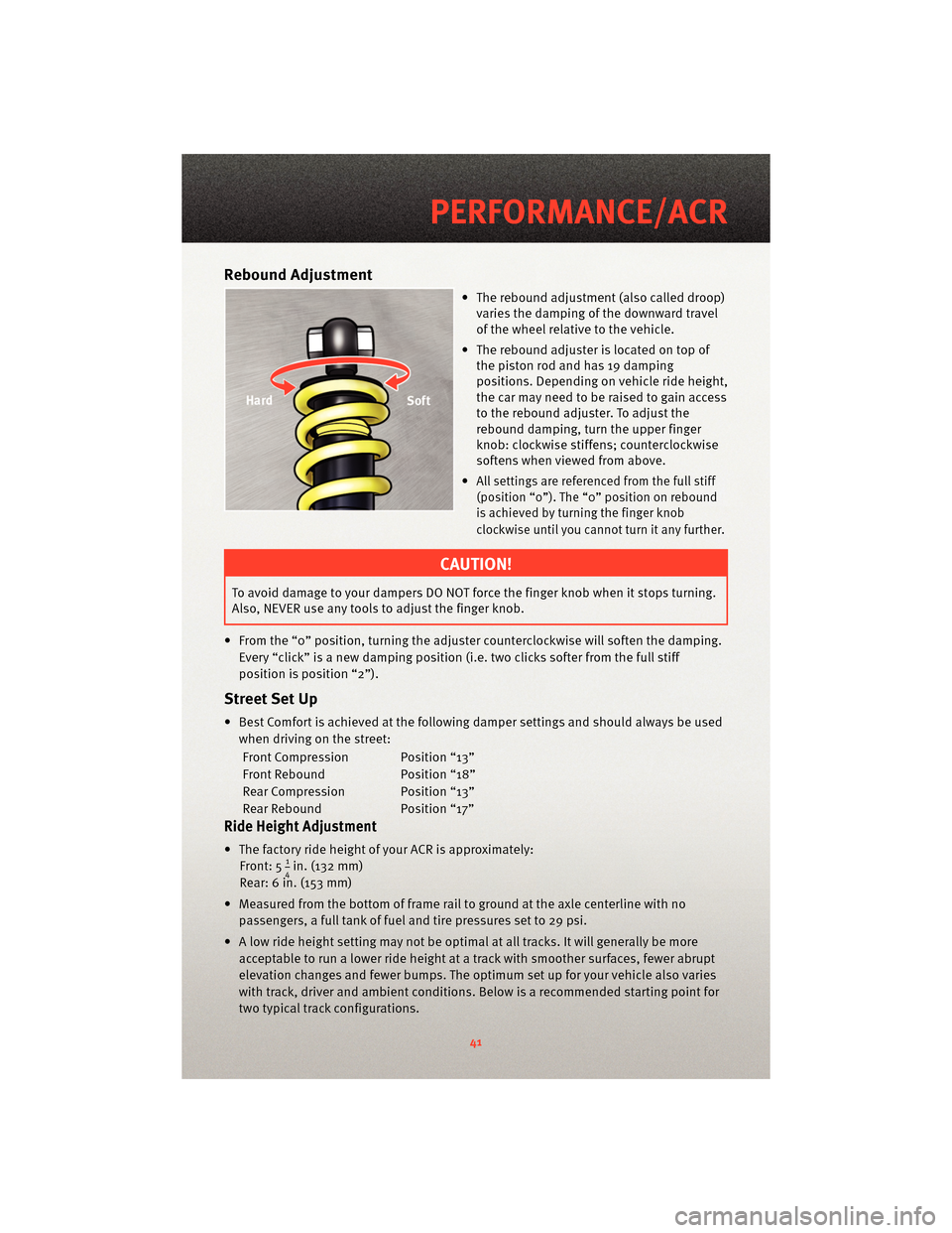
Rebound Adjustment
• The rebound adjustment (also called droop)varies the damping of the downward travel
of the wheel relative to the vehicle.
• The rebound adjuster is located on top of the piston rod and has 19 damping
positions. Depending on vehicle ride height,
the car may need to be raised to gain access
to the rebound adjuster. To adjust the
rebound damping, turn the upper finger
knob: clockwise stiffens; counterclockwise
softens when viewed from above.
•
All settings are referenced from the full stiff
(position “0”). The “0” position on rebound
is achieved by turning the finger knob
clockwise until you cannot turn it any further.
CAUTION!
To avoid damage to your dampers DO NOT force the finger knob when it stops turning.
Also, NEVER use any tools to adjust the finger knob.
• From the “0” position, turning the adjuster cou nterclockwise will soften the damping.
Every “click” is a new damping position (i.e. two clicks softer from the full stiff
position is position “2”).
Street Set Up
• Best Comfort is achieved at the following damper settings and should always be used when driving on the street:
Front Compression Position “13”
Front Rebound Position “18”
Rear Compression Position “13”
Rear Rebound Position “17”
Ride Height Adjustment
• The factory ride height of your ACR is approximately: Front: 514in. (132 mm)
Rear: 6 in. (153 mm)
• Measured from the bottom of frame rail to ground at the axle centerline with no passengers, a full tank of fuel and tire pressures set to 29 psi.
• A low ride height setting may not be optimal at all tracks. It will generally be more acceptable to run a lower ride height at a track with smoother surfaces, fewer abrupt
elevation changes and fewer bumps. The optimum set up for your vehicle also varies
with track, driver and ambient conditions. Below is a recommended starting point for
two typical track configurations.
41
PERFORMANCE/ACR
Page 44 of 80
Smooth track set up:
Front: 4 in. (102 mm)
Rear: 5 3/8 in. (136 mm)
Rough track set up:
Front: 4.375 in. (111 mm)
Rear: 5 1/2 in. (140 mm)
• The rake of the car (or front to rear ride height difference) may also be changed with your ACR suspension. Changing the rake may be beneficial at some tracks. Use
caution when changing the rake angle.
CAUTION!
Depending on your set up, driving styl e, and track condition, some tire to wheel liner
contact may occur. To avoid excessive wheel liner wear, adjust your ride height
accordingly.
Notes on Tuning
Damper Adjustment
• Adjusting from the street settings should be done only at track events. A
recommended starting position for the tracks is:
Front Compression Position “6”
Front Rebound Position “6”
Rear Compression Position “5”
Rear Rebound Position “5”
• Always start from a known position (full stiff).
• Adjust in small increments (1-2 clicks).
• Record your adjustment settings at all four wheels.
• Continually monitor and record your tire pressures.
• Remember that suspension damping, ride heights, rake angle and aerodynamic
balance all work as a system. As you make changes to one end of the vehicle, it will
affect the balance of the car.
Maintenance and Inspection
• Regularly inspect the splitter rub strips and out board knock-in nut. Regularly inspect
all attachments of the aerodynamic components (see Aerodynamics section).
• Track use will greatly increase wear rates and service intervals on your Viper ACR. Repeated track use requires more frequent fluid changes.
NOTE: Although your vehicle is shipped with 0W40, it is recommended to use Mobil-1
15W50 synthetic motor oil at the track.
• Always run a cool down lap at the end of a track outing. For track outings lasting longer than 25 minutes, an external rear axle cooler is recommended.
PERFORMANCE/ACR
42
Page 47 of 80
LIMITED WARRANTY
• The ACR offers many race-ready components that are designed for uncompromising
performance. Because of this, some of the ACR components have unique warranty
limitations.
Racing Not Covered
• The warranty does not cover the cost of repairing damage or conditions caused by racing, nor does it cover the repair for any defects that are found as the result of
participating in a racing event. The term racing includes but is not exclusive to: wheel
to wheel competition, timed competitive events, autocross or other off-road track
events.
Splitter
• The splitter is not covered for wear on the rub strips or damage due to contact with parking blocks, speed bumps, curbs, s loped tarmac, etc. The warranty is not valid if
adjustments or modifications are made to the splitter.
Wing
• The warranty does not cover any adjustments or modifications made to the wing or if the original fasteners or positions have been changed.
Tires
• 12 months / 12,000 miles - Excessive tire wear due to track events, autocross,competition, etc. are not covered.
Brake Pads/Rotors
• 12 months / 12,000 miles - Excessive brake pad and rotor wear due to track events,autocross, competition, etc. are not covered. No warranty for noise complaints.
Adjustable Coil-over Shocks
• The factory warranty is 12 months / 12,000 miles. KW Suspensions has an extendedsupplier warranty up to 36 months or 36,000 miles. The warranty is not valid if
modifications or improper adjustments are made to the factory settings.
KW automotive North America Inc.
1075 North Avenue
Sanger, CA 93657
Toll Free: 1-888-713-5566
Email: [email protected]
http://www.kw-suspension.com/en/
45
PERFORMANCE/ACR
Page 49 of 80
24-HOUR TOWING ASSISTANCE - U.S. ONLY
• Dial toll-free 1-800-521-2779 or 1-800-363-4869 for Canadian residents.
• Provide your name, vehicle identification number and license plate number.
• Provide your location, including telephone number, from which you are calling.
• Briefly describe the nature of the problem and answer a few simple questions.
• You will be given the name of the service provider and an estimated time of arrival. Ifyou feel you are in an “unsafe situation”, please let us know. With your consent, we
will contact local police or safety authorities.
INSTRUMENT CLUSTER WARNING LIGHTS
- Tire Pressure Monitoring System (TPMS) Light
• Each tire, including the spare (if provided), should be checked monthly, when coldand inflated to the inflation pressure recommended by the vehicle manufacturer on
the vehicle placard or tire inflation pressure label. (If your vehicle has tires of a
different size than the size indicated on the v ehicle placard or tire inflation pressure
label, you should determine the proper tire inflation pressure for those tires.)
• As an added safety feature, your vehicle has been equipped with a Tire Pressure Monitoring System (TPMS) that illuminates a low tire pressure telltale when one or
more of your tires is significantly under-inflat ed. Accordingly, when the low tire
pressure telltale illuminates, you should stop and check your tires as soon as
possible, and inflate them to the proper pressure. Driving on a significantly
under-inflated tire causes the tire to overheat and can lead to tire failure.
Under-inflation also reduces fuel efficiency and tire tread life, and may affect the
vehicle’s handling and stopping ability.
• Please note that the TPMS is not a subs titute for proper tire maintenance, and it is the
driver’s responsibility to maintain correct tire pressure, even if under-inflation has not
reached the level to trigger illumination of the TPMS low tire pressure telltale.
• Your vehicle has also been equipped with a TPMS malfunction indicator to indicate
when the system is not operating properly. The TPMS malfunction indicator is
combined with the low tire pressure telltale. When the system detects a malfunction,
the telltale will flash for approximately one minute and then remain continuously
illuminated. This sequence will continue upon subsequent vehicle start-ups as long as
the malfunction exists.
• When the malfunction indicator is illuminated, the system may not be able to detect or signal low tire pressure as intended. TPMS malfunctions may occur for a variety of
reasons, including the installation of replacement or alternate tires or wheels on the
vehicle that prevent the TPMS from functioning properly. Always check the TPMS
malfunction telltale after replacing one or more tires or wheels on your vehicle, to
ensure that the replacement or alternate tires and wheels allow the TPMS to continue
to function properly.
47
WHAT TO DO IN EMERGENCIES
Page 50 of 80
CAUTION!
The TPMS has been optimized for the original equipment tires and wheels. TPMS
pressures and warning have been established for the tire size equipped on your
vehicle. Undesirable system operation or sensor damage may result when using
replacement equipment that is not of the same size, type, and/or style. Aftermarket
wheels can cause sensor damage. Do not use tire sealant from a can, or balance
beads if your vehicle is equipped with a TPMS, as damage to the sensors may result.
- Engine Temperature Warning Light
• This light warns of an overheated engine condition.
• If the light turns on and a warning chime sounds while driving, safely pull over andstop the vehicle. If the A/C system is on, t urn it off. Also, shiftthe transmission into
NEUTRAL and idle the vehicle. If the temperat ure reading does not return to normal,
turn the engine off immediately.
• We recommend that you do not operate the vehicle or engine damage will occur. Have the vehicle serviced immediately.
WARNING!
A hot engine cooling system is dangero us. You or others could be badly burned by
steam or boiling coolant. You may want to call an authorized service center for service
if your vehicle overheats.
- Brake Warning Light
• The Brake Warning light illuminates when there is either a system malfunction or the parking brake is applied. If the light is on and the parking brake is not applied, it
indicates a possible brake hydraulic malfunction, brake booster problem or an
Anti-Lock Brake System problem.
• We recommend you drive to the nearest service center and have the vehicle serviced immediately.
WARNING!
Driving a vehicle with the red brake light on is dangerous. Part of the brake system
may have failed. It will take longer to stop the vehicle. You could have an accident.
Have the vehicle checked immediately.
WHAT TO DO IN EMERGENCIES
48