DODGE VIPER 2015 VX / 3.G Owners Manual
Manufacturer: DODGE, Model Year: 2015, Model line: VIPER, Model: DODGE VIPER 2015 VX / 3.GPages: 400, PDF Size: 9.59 MB
Page 191 of 400
Clear Personal Data
After pressing the “Clear Personal Data Settings” button
on the touchscreen the following settings will be avail-
able:
•Clear Personal Data
When this feature is selected it will remove personal data
including Bluetooth® devices and presets. To remove
personal information, press the “Clear Personal Data”
button and a pop-up will appear asking#Are you sure
you want to clear all personal data?” select “OK” to
Clear, or “Cancel” to exit. Once the data has been cleared,
a pop up appears stating#Personal data cleared.”
System Information
After pressing the “System Information” button on the
touchscreen the following settings will be available:
•System Information
When System Information is selected, a System Informa-
tion screen will appear displaying the system software
version.
SRT Performance Pages
To access the SRT Performance Pages, press the “SRT &
Apps” button on the touchscreen then select the “SRT
Performance Pages” App from the list. Press the UP or
DOWN buttons on the touchscreen to cycle through the
list.
4
UNDERSTANDING YOUR INSTRUMENT PANEL 189
Page 192 of 400
WARNING!
Measurement of vehicle statistics with the SRT Per-
formance Pages is intended for off-highway or off-
road use only and should not be done on any public
roadways. It is recommended that these features be
used in a controlled environment and within the
limits of the law. The capabilities of the vehicle as
measured by the Performance Pages must never be
exploited in a reckless or dangerous manner, which
can jeopardize the user ’s safety or the safety of
others. Only a safe, attentive, and skillful driver can
prevent accidents.
The SRT Performance Pages include the following:
•Home
•Timers
•G-Force
•Gauges 1
•Gauges 2
•Engine
•Options
The following describes each feature and its operation:
Timers
When the Timers Page is selected you will be able to
select from following “Tickets”:
•Current
Pressing the “Current” button displays a “real time”
summary of performance timers.
•Last
Pressing the “Last” button displays the last recorded run
of performance timers.
190 UNDERSTANDING YOUR INSTRUMENT PANEL
Page 193 of 400
•Best
Pressing the “Best” button displays the best recorded run
of performance timers, except for braking data.
•Save
Pressing the “Save” button will let you save the last run.
Any saved run over 10, will overwrite the last saved run
for Uconnect® System storage. The operation of the Save
feature is listed below:
•With a USB jump drive installed, press the “USB”
button to save runs to the jump drive.
•With an SD Card installed, press the “SD Card” to save
runs to the SD Card.
•Press the “Uconnect” button to save the runs to the
Owner web page.
•Press the “Cancel” button to view the last timer
“Ticket.”
The “Tickets” contain the timers listed below:
•0-60 MPH (0-100 km/h)
Displays the time it takes for the vehicle to go from 0 to
60 mph (0 to 100 km/h).
•⅛Mile (200 meter)
Displays the time it takes for the vehicle to go an⅛Mile
(200 meters).
•¼mile (400 meter)
Displays the time it takes for the vehicle to go an¼mile
(400 meters).
•Brake Distance
Displays the distance it takes the vehicle to make a full
stop. Contains current and last data for distance and start
– from speed.
4
UNDERSTANDING YOUR INSTRUMENT PANEL 191
Page 194 of 400
NOTE:The distance measurement will be aborted if the
brake pedal is released before the vehicle comes to a
complete stop.
•Brake Speed
Displays the speed the vehicle is traveling when the
brake pedal is depressed.
NOTE:Brake Distance and Speed timers will only dis-
play#ready#when vehicle is traveling at greater than 30
MPH (48 km/h).
G-Force
When selected, this screen displays all four G-Force
values (two lateral and two longitudinal) as well as
steering angle.
When a G-Force greater than zero is measured, the
display will update the value real-time. As the G-Force
falls, the peak forces will continue to display.
Gauges 1
When selected, this screen displays the following values:
•Oil Temperature
Displays the actual oil temperature.
•Oil Pressure
Displays the actual oil pressure.
•Battery Voltage
Displays the actual battery voltage.
Gauges 2
When selected, this screen displays the following values:
•Coolant Temperature
Displays the actual coolant temperature.
•Oil Temperature
Displays the actual oil temperature.
192 UNDERSTANDING YOUR INSTRUMENT PANEL
Page 195 of 400
•Intake Air Temperature
Displays the actual intake air temperature.
•Oil Pressure
Displays the actual oil pressure.
•Battery Voltage
Displays the actual battery voltage.
Engine
When selected, this screen displays the following values:
•Speed (mph)
Displays the actual speed.
•Horsepower (hp)
Displays the actual horsepower.
•Torque (ft-lb)
Displays the actual torque.
•Oil Pressure (psi)
Displays the actual oil pressure.
Options
When selected, this screen allows you to set your SRT
home page picture, and configure the vehicle color.
Uconnect® RADIOS — IF EQUIPPED
For detailed information about your Uconnect® radio,
refer to your Uconnect® Supplement Manual.
4
UNDERSTANDING YOUR INSTRUMENT PANEL 193
Page 196 of 400
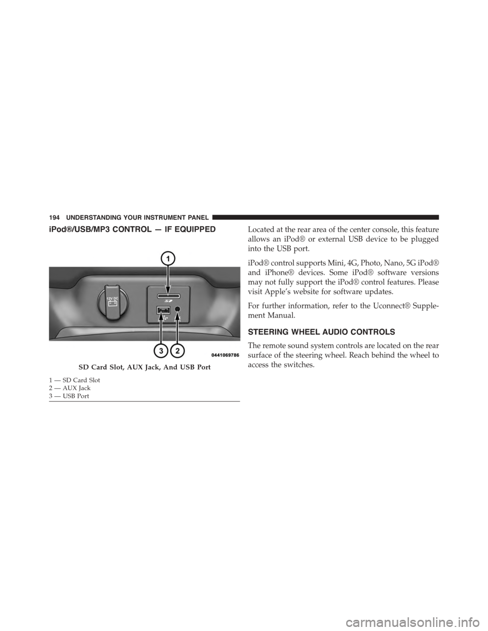
iPod®/USB/MP3 CONTROL — IF EQUIPPEDLocated at the rear area of the center console, this feature
allows an iPod® or external USB device to be plugged
into the USB port.
iPod® control supports Mini, 4G, Photo, Nano, 5G iPod®
and iPhone® devices. Some iPod® software versions
may not fully support the iPod® control features. Please
visit Apple’s website for software updates.
For further information, refer to the Uconnect® Supple-
ment Manual.
STEERING WHEEL AUDIO CONTROLS
The remote sound system controls are located on the rear
surface of the steering wheel. Reach behind the wheel to
access the switches.SD Card Slot, AUX Jack, And USB Port
1—SDCardSlot2 — AUX Jack3—USBPort
194 UNDERSTANDING YOUR INSTRUMENT PANEL
Page 197 of 400
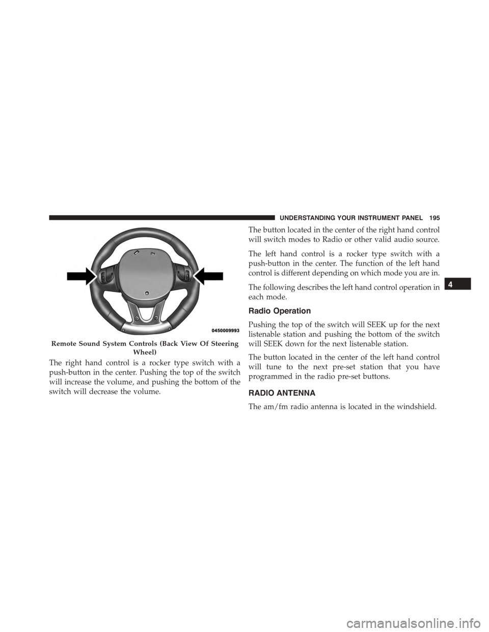
The right hand control is a rocker type switch with a
push-button in the center. Pushing the top of the switch
will increase the volume, and pushing the bottom of the
switch will decrease the volume.
The button located in the center of the right hand control
will switch modes to Radio or other valid audio source.
The left hand control is a rocker type switch with a
push-button in the center. The function of the left hand
control is different depending on which mode you are in.
The following describes the left hand control operation in
each mode.
Radio Operation
Pushing the top of the switch will SEEK up for the next
listenable station and pushing the bottom of the switch
will SEEK down for the next listenable station.
The button located in the center of the left hand control
will tune to the next pre-set station that you have
programmed in the radio pre-set buttons.
RADIO ANTENNA
The am/fm radio antenna is located in the windshield.
Remote Sound System Controls (Back View Of Steering
Wheel)
4
UNDERSTANDING YOUR INSTRUMENT PANEL 195
Page 198 of 400
The Satellite/Navigation antenna is located in the rear
liftgate, while the cellular phone antenna is on the
windshield behind the interior rearview mirror.
RADIO OPERATION AND MOBILE PHONES
Under certain conditions, the mobile phone being on in
your vehicle can cause erratic or noisy performance from
your radio. This condition may be lessened or eliminated
by relocating the mobile phone antenna. This condition is
not harmful to the radio. If your radio performance does
not satisfactorily “clear” by the repositioning of the
antenna, it is recommended that the radio volume be
turned down or off during mobile phone operation when
not using Uconnect® (if equipped).
General Information
This device complies with Part 15 of the FCC rules and
RSS 210 of Industry Canada. Operation is subject to the
following conditions:
•Changes or modifications not expressly approved by
the party responsible for compliance could void the
user’s authority to operate the equipment.
•This device may not cause harmful interference.
•This device must accept any interference received,
including interference that may cause undesired op-
eration.
CLIMATE CONTROLS
The Climate Control System allows you to regulate the
temperature, amount, and direction of air circulating
throughout the vehicle. The controls are located on the
instrument panel below the radio.
196 UNDERSTANDING YOUR INSTRUMENT PANEL
Page 199 of 400
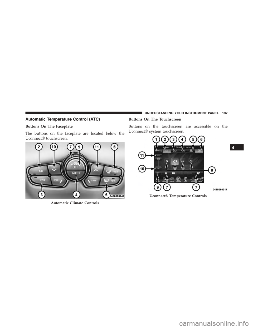
Automatic Temperature Control (ATC)
Buttons On The Faceplate
The buttons on the faceplate are located below the
Uconnect® touchscreen.
Buttons On The Touchscreen
Buttons on the touchscreen are accessible on the
Uconnect® system touchscreen.
Automatic Climate Controls
Uconnect® Temperature Controls
4
UNDERSTANDING YOUR INSTRUMENT PANEL 197
Page 200 of 400
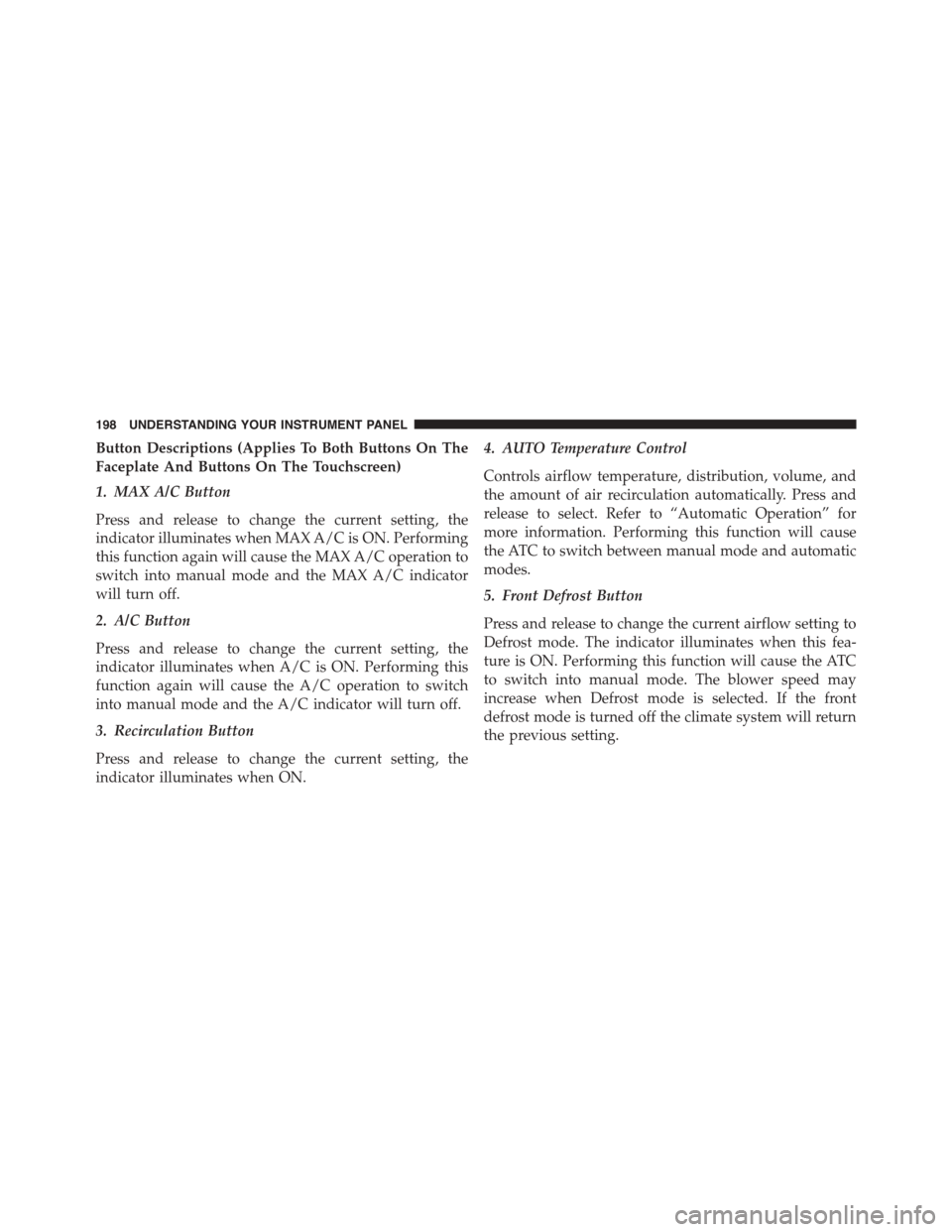
Button Descriptions (Applies To Both Buttons On The
Faceplate And Buttons On The Touchscreen)
1. MAX A/C Button
Press and release to change the current setting, the
indicator illuminates when MAX A/C is ON. Performing
this function again will cause the MAX A/C operation to
switch into manual mode and the MAX A/C indicator
will turn off.
2. A/C Button
Press and release to change the current setting, the
indicator illuminates when A/C is ON. Performing this
function again will cause the A/C operation to switch
into manual mode and the A/C indicator will turn off.
3. Recirculation Button
Press and release to change the current setting, the
indicator illuminates when ON.
4. AUTO Temperature Control
Controls airflow temperature, distribution, volume, and
the amount of air recirculation automatically. Press and
release to select. Refer to “Automatic Operation” for
more information. Performing this function will cause
the ATC to switch between manual mode and automatic
modes.
5. Front Defrost Button
Press and release to change the current airflow setting to
Defrost mode. The indicator illuminates when this fea-
ture is ON. Performing this function will cause the ATC
to switch into manual mode. The blower speed may
increase when Defrost mode is selected. If the front
defrost mode is turned off the climate system will return
the previous setting.
198 UNDERSTANDING YOUR INSTRUMENT PANEL