ABS DODGE VIPER 2015 VX / 3.G Owners Manual
[x] Cancel search | Manufacturer: DODGE, Model Year: 2015, Model line: VIPER, Model: DODGE VIPER 2015 VX / 3.GPages: 400, PDF Size: 9.59 MB
Page 20 of 400
To Disarm The System
The Vehicle Security Alarm can be disarmed using any of
the following methods:
•Push the UNLOCK button on the Remote Keyless
Entry (RKE) transmitter.
•Cycle the vehicle ignition system out of the OFF
position:
•Push the Keyless Enter-N-Go™ Start/Stop button
(requires at least one valid Key Fob in the vehicle).
NOTE:
•The liftgate key cylinder cannot arm or disarm the
Vehicle Security Alarm.
•When the Vehicle Security Alarm is armed, the interior
power door lock switches will not unlock the doors.
The Vehicle Security Alarm is designed to protect your
vehicle. However, you can create conditions where the
system will give you a false alarm. If one of the previ-
ously described arming sequences has occurred, the
Vehicle Security Alarm will arm regardless of whether
you are in the vehicle or not. If you remain in the vehicle
and open a door, the alarm will sound. If this occurs,
disarm the Vehicle Security Alarm.
If the Vehicle Security Alarm is armed and the battery
becomes disconnected, the Vehicle Security Alarm will
remain armed when the battery is reconnected; the
exterior lights will flash, and the horn will sound. If this
occurs, disarm the Vehicle Security Alarm.
Tamper Alert
If something has triggered the Vehicle Security Alarm in
your absence, the horn will sound three times, and the
exterior lights will blink three times when you disarm the
Vehicle Security Alarm. Check the vehicle for tampering.
18 THINGS TO KNOW BEFORE STARTING YOUR VEHICLE
Page 149 of 400
indicate that the parking brake is applied, that the brake
fluid level is low, or that there is a problem with the
anti-lock brake system reservoir.
If the light remains on when the parking brake has been
disengaged, and the fluid level is at the full mark on the
master cylinder reservoir, it indicates a possible brake
hydraulic system malfunction or that a problem with the
Brake Booster has been detected by the Anti-Lock Brake
System (ABS) / Electronic Stability Control (ESC) system.
In this case, the light will remain on until the condition
has been corrected. If the problem is related to the brake
booster, the ABS pump will run when applying the brake
and a brake pedal pulsation may be felt during each stop.
The dual brake system provides a reserve braking capac-
ity in the event of a failure to a portion of the hydraulic
system. A leak in either half of the dual brake system is
indicated by the Brake Warning Light, which will turn on
when the brake fluid level in the master cylinder has
dropped below a specified level.
The light will remain on until the cause is corrected.
NOTE:The light may flash momentarily during sharp
cornering maneuvers, which change fluid level condi-
tions. The vehicle should have service performed, and
the brake fluid level checked.
If brake failure is indicated, immediate repair is neces-
sary.
WARNING!
Driving a vehicle with the red brake light on is
dangerous. Part of the brake system may have failed.
It will take longer to stop the vehicle. You could have
a collision. Have the vehicle checked immediately.
Vehicles equipped with the Anti-Lock Brake System
(ABS), are also equipped with Electronic Brake Force
Distribution (EBD). In the event of an EBD failure, the
4
UNDERSTANDING YOUR INSTRUMENT PANEL 147
Page 150 of 400
Brake Warning Light will turn on along with the ABS
Light. Immediate repair to the ABS system is required.
Operation of the Brake Warning Light can be checked by
turning the ignition switch from the OFF position to the
ON/RUN position. The light should illuminate for ap-
proximately two seconds. The light should then turn off
unless the parking brake is applied or a brake fault is
detected. If the light does not illuminate, have the light
inspected by an authorized dealer.
The light also will turn on when the parking brake is
applied with the ignition switch in the ON/RUN posi-
tion.
NOTE:This light shows only that the parking brake is
applied. It does not show the degree of brake application.
8. Tachometer
This gauge measures engine revolutions-per-minute
(RPM x 1000).
9. Oil Pressure Gauge Warning Light
Oil Pressure Primary Gauge and Secondary gauge
Warning The Oil pressure Primary and Secondary gage
indicate the oil current pressure. When the oil pressure
falls below a specific value (currently 10 psi), both of the
gauges will light up RED and flash for about 3 seconds.
This oil pressure indication may also occur when the
engine is first started. If the gauges turn RED while
driving, stop the vehicle and shut off the engine as soon
as possible
10. Vehicle Security Light — If Equipped
This light will flash at a fast rate for approxi-
mately 15 seconds, when the vehicle security
alarm is arming, and then will flash slowly
until the vehicle is disarmed.
148 UNDERSTANDING YOUR INSTRUMENT PANEL
Page 157 of 400
19. Anti-Lock Brake (ABS) Light
This light monitors the Anti-Lock Brake System
(ABS). The light will turn on when the ignition
is cycled to the ON/RUN position and may
stay on for as long as four seconds.
If the ABS light remains on or turns on while driving, it
indicates that the Anti-Lock portion of the brake system
is not functioning and that service is required. However,
the conventional brake system will continue to operate
normally if the BRAKE warning light is not on.
If the ABS light is on, the brake system should be serviced
as soon as possible to restore the benefits of Anti-Lock
brakes. If the ABS light does not turn on when the
ignition is cycled to the ON/RUN position, have the light
inspected by an authorized dealer.
20. Park/Headlight ON Indicator — If Equipped
This indicator will illuminate when the park
lights or headlights are turned on.
21. Electronic Stability Control (ESC) OFF Indicator
Light
This light indicates the Electronic Stability Con-
trol (ESC) is off.
4
UNDERSTANDING YOUR INSTRUMENT PANEL 155
Page 240 of 400
The “Brake System Warning Light” in the instrument
cluster will turn on when the ignition is in the ON/RUN
position and the parking brake is applied.
NOTE:
•This light only shows that the parking brake is applied
or a brake/ABS system fault. It does not show the
degree of brake application. If the “Brake System
Warning Light” is illuminated when the parking brake
is not applied please see your authorized dealer.
•Each time the parking brake is applied, the instrument
cluster will automatically go to the highest illumina-
tion setting regardless of the dimmer control setting.
WARNING!
•Never leave children alone in a vehicle, or with
access to an unlocked vehicle. Allowing children to
be in a vehicle unattended is dangerous for a
number of reasons. A child or others could be
injured seriously or fatally. Do not leave the key
fob in or near the vehicle (or in a location accessible
to children), and do not leave the ignition of a
vehicle equipped with Keyless Enter-N-Go in the
ACC or ON/RUN mode. A child could operate
power windows, other controls, or move the ve-
hicle.
•Ensure the parking brake is fully disengaged be-
fore driving. Failure to do so can lead to brake
failure, and an accident.
238 STARTING AND OPERATING
Page 243 of 400
ELECTRONIC BRAKE CONTROL SYSTEM
Your vehicle is equipped with an advanced electronic
brake control system that includes the Anti-Lock Brake
System (ABS), Traction Control System (TCS), and Elec-
tronic Stability Control (ESC). All of these systems work
together to enhance vehicle stability and control in vari-
ous driving conditions.
Anti-Lock Brake System
The Anti-Lock Brake System (ABS) is designed to aid the
driver in maintaining vehicle control under adverse
braking conditions. The system operates with a separate
computer to modulate hydraulic pressure to prevent
wheel lock-up and help avoid skidding on slippery
surfaces.
NOTE:During severe braking conditions, a pulsing sen-
sation may occur and a clicking noise will be heard. This
is normal, indicating that the ABS is functioning.
The ABS conducts a low-speed self-test at approximately
12 mph (20 km/h). If you have your foot lightly on the
brake pedal while this test is occurring, you may feel a
slight pedal movement. The movement can be more
apparent on ice and snow and be considered normal.
The ABS pump motor runs during the self-test at 12 mph
(20 km/h) and during an ABS stop. The pump motor
makes a low humming noise during operation, which is
normal.
CAUTION!
The Anti-Lock Brake System is subject to possible
detrimental effects of electronic interference caused
by improperly installed aftermarket radios or tele-
phones.
5
STARTING AND OPERATING 241
Page 244 of 400
WARNING!
•The Anti-Lock Brake System (ABS) contains so-
phisticated electronic equipment that may be sus-
ceptible to interference caused by improperly in-
stalled or high output radio transmitting
equipment. This interference can cause possible
loss of anti-lock braking capability. Installation of
such equipment should be performed by qualified
professionals.
•Pumping of the Anti-Lock Brakes will diminish
their effectiveness and may lead to a collision.
Pumping makes the stopping distance longer. Just
press firmly on your brake pedal when you need to
slow down or stop.
(Continued)
WARNING!(Continued)
•The Anti-Lock Brake System (ABS) cannot prevent
the natural laws of physics from acting on the
vehicle, nor can it increase braking or steering
efficiency beyond that afforded by the condition of
the vehicle brakes and tires or the traction afforded.
•The Anti-Lock Brake System (ABS) cannot prevent
collisions, including those resulting from excessive
speed in turns, following another vehicle too
closely, or hydroplaning.
•The capabilities of an Anti-Lock Brake System
(ABS) equipped vehicle must never be exploited in
a reckless or dangerous manner, that could jeopar-
dize the user’s safety or the safety of others.
All vehicle wheels and tires must be the same size and
type as the original equipment and the tires must be
242 STARTING AND OPERATING
Page 245 of 400
properly inflated to produce accurate signals for the
computer.
WARNING!
Significant over or underinflation of tires, or mixing
sizes of tires or wheels on the vehicle can lead to loss
of braking effectiveness.
Anti-Lock Brake Warning Light
The “Anti-Lock Brake Warning Light” will turn
on and stay on briefly as a bulb check when the
ignition is first turned on. If the light does not
turn on during starting, have it repaired
promptly.
This light also illuminates at vehicle start-up to indicate
that the ABS self-check is in process. If the light remains
on after start-up, or turns on and remains on at road
speeds, it may indicate a system malfunction or that the
system is inoperative. In this case, the system reverts to
standard non-anti-lock brakes. If this occurs, safely bring
the vehicle to a complete stop as soon as possible and
cycle the ignition to attempt to reset the ABS. If the light
remains on, see your authorized dealer immediately to
have the system serviced. Also, if the “BRAKE Warning
Light” and the “ABS Warning Light” are on, and the
parking brake is fully released, see your authorized
dealer immediately.
Traction Control System (TCS)
The TCS system monitors the amount of wheel spin of
each driven wheel. If wheel spin is detected, brake
pressure is applied to the slipping wheel(s) and engine
power is reduced to provide enhanced acceleration and
stability.
5
STARTING AND OPERATING 243
Page 250 of 400
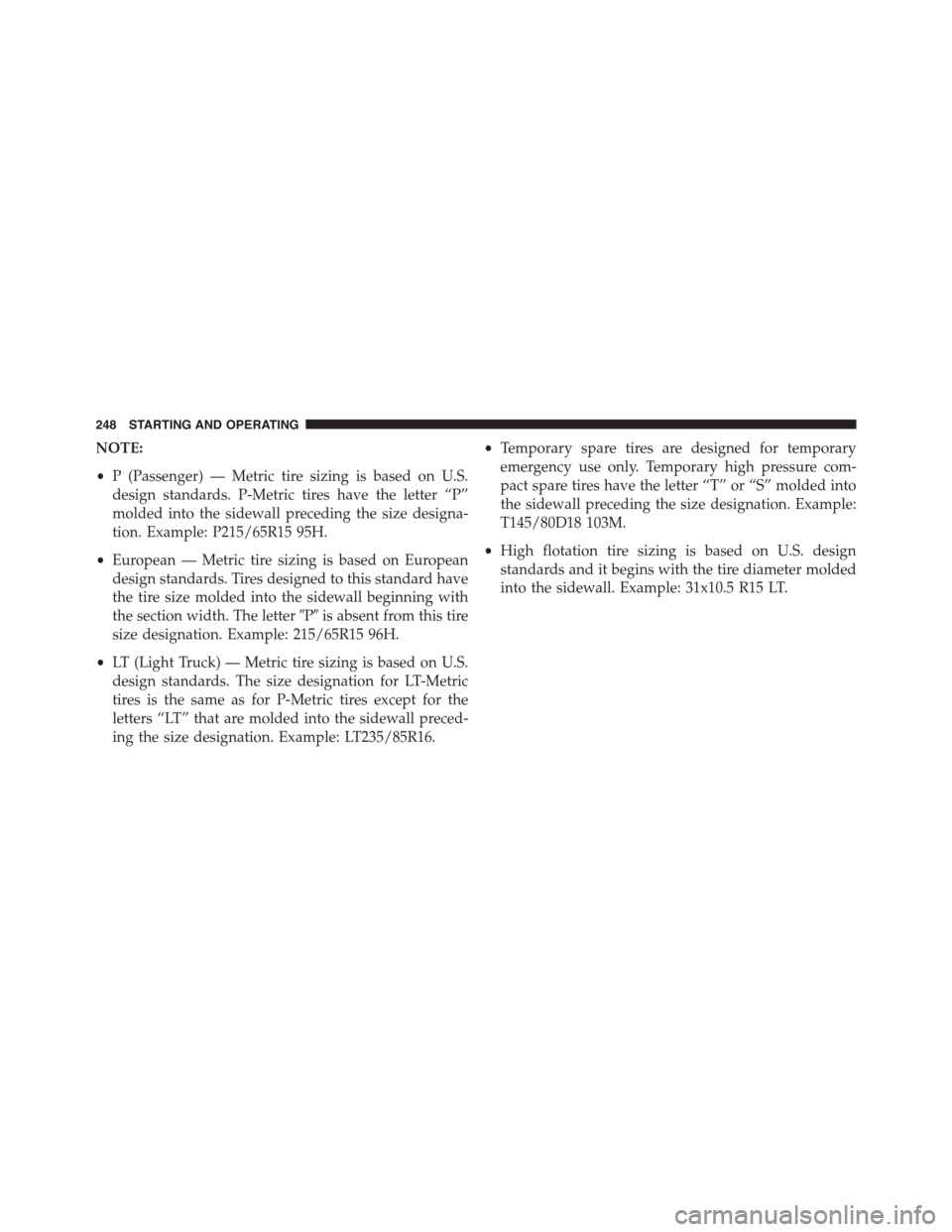
NOTE:
•P (Passenger) — Metric tire sizing is based on U.S.
design standards. P-Metric tires have the letter “P”
molded into the sidewall preceding the size designa-
tion. Example: P215/65R15 95H.
•European — Metric tire sizing is based on European
design standards. Tires designed to this standard have
the tire size molded into the sidewall beginning with
the section width. The letter#P#is absent from this tire
size designation. Example: 215/65R15 96H.
•LT (Light Truck) — Metric tire sizing is based on U.S.
design standards. The size designation for LT-Metric
tires is the same as for P-Metric tires except for the
letters “LT” that are molded into the sidewall preced-
ing the size designation. Example: LT235/85R16.
•Temporary spare tires are designed for temporary
emergency use only. Temporary high pressure com-
pact spare tires have the letter “T” or “S” molded into
the sidewall preceding the size designation. Example:
T145/80D18 103M.
•High flotation tire sizing is based on U.S. design
standards and it begins with the tire diameter molded
into the sidewall. Example: 31x10.5 R15 LT.
248 STARTING AND OPERATING
Page 252 of 400
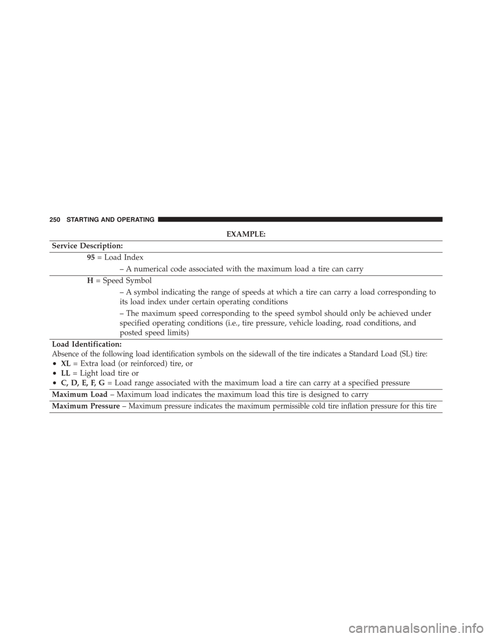
EXAMPLE:
Service Description:
95= Load Index
– A numerical code associated with the maximum load a tire can carry
H= Speed Symbol
– A symbol indicating the range of speeds at which a tire can carry a load corresponding to
its load index under certain operating conditions
– The maximum speed corresponding to the speed symbol should only be achieved under
specified operating conditions (i.e., tire pressure, vehicle loading, road conditions, and
posted speed limits)
Load Identification:
Absence of the following load identification symbols on the sidewall of the tire indicates a Standard Load (SL) tire:
•XL= Extra load (or reinforced) tire, or
•LL= Light load tire or
•C, D, E, F, G= Load range associated with the maximum load a tire can carry at a specified pressure
Maximum Load– Maximum load indicates the maximum load this tire is designed to carry
Maximum Pressure–Maximum pressure indicates the maximum permissible cold tire inflation pressure for this tire
250 STARTING AND OPERATING