maintenance DODGE VIPER 2015 VX / 3.G Owners Manual
[x] Cancel search | Manufacturer: DODGE, Model Year: 2015, Model line: VIPER, Model: DODGE VIPER 2015 VX / 3.GPages: 400, PDF Size: 9.59 MB
Page 3 of 400
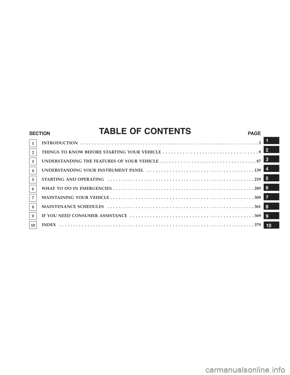
TABLE OF CONTENTSSECTIONPAGE
1INTRODUCTION ...............................................................3
2THINGS TO KNOW BEFORE STARTING YOUR VEHICLE..................................9
3UNDERSTANDING THE FEATURES OF YOUR VEHICLE..................................87
4UNDERSTANDING YOUR INSTRUMENT PANEL......................................139
5STARTING AND OPERATING . . . . . . . . . . . . . . . . . . . . . . . . . . . . . . . . . . . . . . . . . . . . . . . . . . . . 219
6WHAT TO DO IN EMERGENCIES . . . . . . . . . . . . . . . . . . . . . . . . . . . . . . . . . . . . . . . . . . . . . . . . . . 289
7MAINTAINING YOUR VEHICLE . . . . . . . . . . . . . . . . . . . . . . . . . . . . . . . . . . . . . . . . . . . . . . . . . . . 309
8MAINTENANCE SCHEDULES....................................................361
9IF YOU NEED CONSUMER ASSISTANCE............................................369
10INDEX . . . . . . . . . . . . . . . . . . . . . . . . . . . . . . . . . . . . . . . . . . . . . . . . . . . . . . . . . . . . . . . . . . . . . 379
1
2
3
4
5
6
7
8
9
10
Page 6 of 400
INTRODUCTION
Congratulations on selecting your new FCA US LLC
vehicle. Be assured that it represents precision workman-
ship, distinctive styling, and high quality - all essentials
that are traditional to our vehicles.
This Owner’s Manual has been prepared with the assis-
tance of service and engineering specialists to acquaint
you with the operation and maintenance of your vehicle.
It is supplemented by Warranty Information, and various
customer-oriented documents. Please take the time to
read these publications carefully. Following the instruc-
tions and recommendations in this manual will help
assure safe and enjoyable operation of your vehicle.
NOTE: After reviewing the owner information, it
should be stored in the vehicle for convenient referenc-
ing and remain with the vehicle when sold.
When it comes to service, remember that your authorized
dealer knows your vehicle best, has factory-trained tech-
nicians and genuine parts, and cares about your satisfac-
tion.
HOW TO USE THIS MANUAL
Consult the Table of Contents to determine which section
contains the information you desire.
Since the specification of your vehicle depends on the
items of equipment ordered, certain descriptions and
illustrations may differ from your vehicle’s equipment.
The detailed index at the back of this Owner’s Manual
contains a complete listing of all subjects.
Consult the following table for a description of the
symbols that may be used on your vehicle or throughout
this Owner’s Manual:
4INTRODUCTION
Page 70 of 400
diagnostics also record the nature of the malfunction.
While the air bag system is designed to be maintenance
free, if any of the following occurs, have an authorized
dealer service the air bag system immediately.
•The Air Bag Warning Light does not come on during
the four to eight seconds when the ignition is first
placed in the ON/RUN position.
•The Air Bag Warning Light remains on after the four to
eight-second interval.
•The Air Bag Warning Light comes on intermittently or
remains on while driving.
NOTE:If the speedometer, tachometer, or any engine
related gauges are not working, the Occupant Restraint
Controller (ORC) may also be disabled. In this condition
the air bags may not be ready to inflate for your protec-
tion. Have an authorized dealer service the air bag
system immediately.
WARNING!
Ignoring the Air Bag Warning Light in your instru-
ment panel could mean you won’t have the air bags
to protect you in a collision. If the light does not come
on as a bulb check when the ignition is first placed in
the on position, and stays on after you start the
vehicle, or if it comes on as you drive, have an
authorized dealer service the air bag system immedi-
ately.
68 THINGS TO KNOW BEFORE STARTING YOUR VEHICLE
Page 151 of 400
11. High Beam Indicator
This indicator shows that the high beam head-
lights are on. Push the multifunction lever for-
ward to switch the headlights to high beam, and pull
toward yourself (normal position) to return to low beam.
12. Fuel Gauge/Fuel Door Reminder
The pointer shows the level of fuel in the fuel tank when
the ignition is in the ON/RUN position. The arrow in this
symbol is a reminder that the Fuel Filler Door is located
on the left side of the vehicle.
13. Tire Pressure Monitoring Telltale Light — If
Equipped
Each tire, including the spare (if provided)
should be checked monthly when cold and
inflated to the inflation pressure recommended
by the vehicle manufacturer on the vehicle
placard or tire inflation pressure label. (If your vehicle
has tires of a different size than the size indicated on the
vehicle placard or tire inflation pressure label, you should
determine the proper tire inflation pressure for those
tires).
As an added safety feature, your vehicle has been
equipped with a Tire Pressure Monitoring System
(TPMS) that illuminates a low tire pressure telltale when
one or more of your tires is significantly under-inflated.
Accordingly, when the low tire pressure telltale illumi-
nates, you should stop and check your tires as soon as
possible, and inflate them to the proper pressure. Driving
on a significantly under-inflated tire causes the tire to
overheat and can lead to tire failure. Under-inflation also
reduces fuel efficiency and tire tread life, and may affect
the vehicle’s handling and stopping ability.
Please note that the TPMS is not a substitute for proper
tire maintenance, and it is the driver ’s responsibility to
4
UNDERSTANDING YOUR INSTRUMENT PANEL 149
Page 204 of 400
feature. Refer to the “Customer Programmable Fea-
tures — Uconnect® System Settings” in this section of
the manual.
To provide you with maximum comfort in the Automatic
mode during cold start-ups, the blower fan will remain
on low until the engine warms up. The blower will
increase in speed and transition into Auto mode.
Recirculation Control
When outside air contains smoke, odors, or high humid-
ity, or if rapid cooling is desired, you may wish to
recirculate interior air by pressing the RECIRCULATION
control button. Recirculation mode should only be used
temporarily. The recirculation LED will illuminate on the
blower control knob when this button is selected. Push
the button a second time to turn off the Recirculation
mode LED and allow outside air into the vehicle.
NOTE:In cold weather, use of Recirculation mode may
lead to excessive window fogging. The Recirculation
mode is not allowed in Defrost mode to improve window
clearing operation. Recirculation will be disabled auto-
matically if these modes are selected.
Summer Operation
The engine cooling system must be protected with a
high-quality antifreeze coolant to provide proper corro-
sion protection and to protect against engine overheating.
OAT coolant (conforming to MS.90032) is recommended.
Refer to “Maintenance Procedures” in “Maintaining Your
Vehicle” for proper coolant selection.
Winter Operation
To ensure the best possible heater and defroster perfor-
mance, make sure the engine cooling system is function-
ing properly and the proper amount, type, and concen-
tration of coolant is used. Refer to “Maintenance
Procedures” in “Maintaining Your Vehicle” for proper
202 UNDERSTANDING YOUR INSTRUMENT PANEL
Page 273 of 400
tires. Rotation will increase tread life, help to maintain
mud, snow, and wet traction levels, and contribute to a
smooth, quiet ride.
Refer to the “Maintenance Schedule” for the proper
maintenance interval. Remember, more frequent rotation
is permissible if desired. Also, correct for anything caus-
ing rapid or unusual wear prior to performing the tire
rotation.
NOTE:Each wheel on your vehicle contains a tire pres-
sure sensor. The Tire Pressure Monitor System (TPMS)
learns the location of each sensor though system pro-
gramming. Although not required, the manufacturer
recommends reprogramming the TPMS after rotating the
tires so that the system can relearn each sensor ’s location.
See your authorized dealer for system reprogramming.
The front and rear tires are different sizes and cannot be
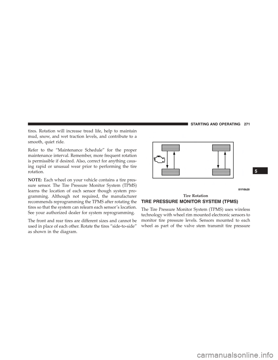
used in place of each other. Rotate the tires “side-to-side”
as shown in the diagram.
TIRE PRESSURE MONITOR SYSTEM (TPMS)
The Tire Pressure Monitor System (TPMS) uses wireless
technology with wheel rim mounted electronic sensors to
monitor tire pressure levels. Sensors mounted to each
wheel as part of the valve stem transmit tire pressure
Tire Rotation
5
STARTING AND OPERATING 271
Page 276 of 400
CAUTION!(Continued)
•After inspecting or adjusting the tire pressure,
always reinstall the valve stem cap. This will
prevent moisture and dirt from entering the valve
stem, which could damage the TPM sensor.
NOTE:
•The TPMS is not intended to replace normal tire care
and maintenance or to provide warning of a tire failure
or condition.
•The TPMS should not be used as a tire pressure gauge
while adjusting your tire pressure.
•Driving on a significantly under-inflated tire causes
the tire to overheat and can lead to tire failure.
Under-inflation also reduces fuel efficiency and tire
tread life, and may affect the vehicle’s handling and
stopping ability.
•The TPMS is not a substitute for proper tire mainte-
nance, and it is the driver ’s responsibility to maintain
correct tire pressure using an accurate tire pressure
gauge, even if under-inflation has not reached the level
to trigger illumination of the TPM Telltale Light.
•Seasonal temperature changes will affect tire pressure,
and the TPMS will monitor the actual tire pressure in
the tire.
Premium System
The Tire Pressure Monitor System (TPMS) uses wireless
technology with wheel rim mounted electronic sensors to
monitor tire pressure levels. Sensors mounted to each
wheel as part of the valve stem transmit tire pressure
readings to the receiver module. It is particularly impor-
tant for you to check the tire pressure in all of the tires on
your vehicle monthly and to maintain the proper pres-
sure. The TPMS consists of the following components:
274 STARTING AND OPERATING
Page 311 of 400
MAINTAINING YOUR VEHICLE
CONTENTS
!ENGINE COMPARTMENT — 8.4L..........311
!ONBOARD DIAGNOSTIC SYSTEM (OBD II) . . .312
!EMISSIONS INSPECTION AND MAINTENANCE
PROGRAMS..........................312
!REPLACEMENT PARTS..................314
!DEALER SERVICE......................314
!MAINTENANCE PROCEDURES...........315
▫Engine Oil..........................315
▫Engine Oil Filter......................317
▫Engine Air Cleaner Filter................318
▫Maintenance-Free Battery...............318
▫Hibernation Mode....................320
▫Air Conditioner Maintenance.............321
▫Body Lubrication.....................322
▫Wiper Blades........................323
▫Adding Washer Fluid..................323
▫Exhaust System......................324
▫Cooling System......................326
▫Brake System........................332
▫Manual Transmission..................335
7
Page 314 of 400
ONBOARD DIAGNOSTIC SYSTEM (OBD II)
To meet new government regulations and promote
cleaner air, your vehicle is equipped with a sophisticated
onboard diagnostic system called OBD II. This system
monitors the performance of the emissions and engine
control systems. When these systems are operating prop-
erly, your vehicle will provide excellent performance and
fuel economy, as well as engine emissions well within
current government regulations.
If any of these systems require service, the OBD II system
will turn on the Malfunction Indicator Light. It will also
store diagnostic codes and other information to assist
your service technician in making repairs. Although your
vehicle will usually be drivable and not need towing, see
your authorized dealer for service as soon as possible.
CAUTION!
Prolonged driving with the light on could cause
further damage to the emission control system. It
could also affect fuel economy and driveability. The
vehicle must be serviced before any state emissions
tests can be performed.
If the light is flashing, severe catalytic converter damage
and power loss will soon occur. Immediate service is
required.
EMISSIONS INSPECTION AND MAINTENANCE
PROGRAMS
In some localities, it may be a legal requirement to pass
an inspection of your vehicle’s emissions control system.
Failure to pass could prevent vehicle registration.
For states that require an Inspection and Mainte-
nance (I/M), this check verifies the “Malfunction
312 MAINTAINING YOUR VEHICLE
Page 316 of 400
recently serviced or had a battery failure or replacement,
you may need to do nothing more than drive your
vehicle as you normally would in order for your OBD II
system to update. A recheck with the above test routine
may then indicate that the system isnow ready.
Regardless of whether your vehicle’s OBD II system is
ready or not, if the MIL is illuminated during normal
vehicle operation you should have your vehicle serviced
before going to the I/M station. The I/M station can fail
your vehicle because the MIL is on with the engine
running.
REPLACEMENT PARTS
Use of genuine MOPAR® parts for normal/scheduled
maintenance and repairs is highly recommended to en-
sure the designed performance. Damage or failures
caused by the use of non-MOPAR® parts for mainte-
nance and repairs will not be covered by the New Vehicle
Limited Warranty.
DEALER SERVICE
Your authorized dealer has the qualified service person-
nel, special tools, and equipment to perform all service
operations in an expert manner. Service Manuals are
available which include detailed service information for
your vehicle. Refer to these Service Manuals before
attempting any procedure yourself.
NOTE:Intentional tampering with emissions control
systems may void your warranty and could result in civil
penalties being assessed against you.
WARNING!
You can be badly injured working on or around a motor
vehicle. Only do service work for which you have the
knowledge and the proper equipment. If you have any
doubt about your ability to perform a service job, take
your vehicle to a competent mechanic.
314 MAINTAINING YOUR VEHICLE