suspension DODGE VIPER 2015 VX / 3.G Owners Manual
[x] Cancel search | Manufacturer: DODGE, Model Year: 2015, Model line: VIPER, Model: DODGE VIPER 2015 VX / 3.GPages: 400, PDF Size: 9.59 MB
Page 161 of 400
The DID display is located in the center portion of the
instrument cluster and consists of the following sections:
1. Main Screen — The inner ring of the display will
illuminate in grey under normal conditions, yellow for
non critical warnings, red for critical warnings, and
white for on demand information.
2. Audio / Phone Information and Sub-menu Informa-
tion — Whenever there are sub-menus available, the
position within the sub-menus is shown here.
3. Reconfigurable Telltales/Information
4. Telltales/Indicators
5. Selectable Information (Tach, Mph/Kmh, Vehicle Info,
Fuel Economy, Trip A, Trip B, Audio, Stored Messages,
Screen Setup, Performance, Diagnostics, Hibernation)
6. Suspension Status — The suspension status icon will
illuminate in this area. Refer to “Starting And Operat-
ing” for further information.
7. ESC Status — The ESC status icon will illuminate in
this area. Refer to “Starting And Operating” for fur-
ther information.
8. Launch Control status when launch control mode is
entered. Refer to “Starting And Operating” for further
information.
4
UNDERSTANDING YOUR INSTRUMENT PANEL 159
Page 231 of 400
CAUTION!
If you skip more than one gear while downshifting
or downshift at too high a vehicle speed, you could
damage the engine, transmission, or clutch.
WARNING!
Skipping more than one gear while downshifting,
could cause you to lose control of your vehicle. You
could have a collision.
STREET/RACE MODE — IF EQUIPPED
This vehicle is equipped with a two mode electronic
controlled damping system. This system allows for a
compliant street suspension damping setting or a firmer
race suspension damping setting. When in street mode
the system will automatically shift the suspension damp-
ers to the firmer Race damping setting during some hard
acceleration and braking situations. There are two modes
of operation:
•Street Mode — This mode will give a sporty, but
comfortable ride. This mode is driver selectable when
the vehicle is placed in STREET mode (press the
“STREET” button on the Instrument Panel). This mode
is intended for a smoother ride on the various types of
pavement and road conditions while still providing
damping levels appropriate extreme capabilities.
•Race Mode — This mode is driver selectable when the
vehicle is placed in RACE mode (press the “RACE”
button on the Instrument Panel). This mode is for track
use only and will supply maximum grip to the tires.
5
STARTING AND OPERATING 229
Page 232 of 400
NOTE:
•With the ignition in the ON/RUN position, the sus-
pension damping system will be in the last mode the
system was in when the vehicle was turned off. The
driver can select either Street or Race damping mode
at any time.
•The suspension mode will lock and stay in whatever
the driver selects even when the ignition is turned off
and the car restarted.
•The RACE setting will provide a much firmer ride.
•When RACE mode is enabled, a Shock symbol with
“RACE” next to it will light up in the instrument
cluster.
LAUNCH MODE
This system maximizes acceleration traction for straight
line racing.
1. Bring the vehicle to complete stop on a level track
surface with the engine running.
2. Set the steering wheel for straight ahead driving.
3. Fully depress the clutch and select the first gear
position.
4. Press and release the “LAUNCH” Button (Located on
the steering wheel controls).
230 STARTING AND OPERATING
Page 349 of 400
Cavity Relay Cartridge
Fuse
Mini-Fuse Description
33 — 20 Amp
Yellow
— Run Acc relay
34 — — — B+ Jumper
35———Spare
36——10 Amp Red ORC Mod Run
37——15 Amp Blue Cluster, Camera
38——20 Amp
Yellow
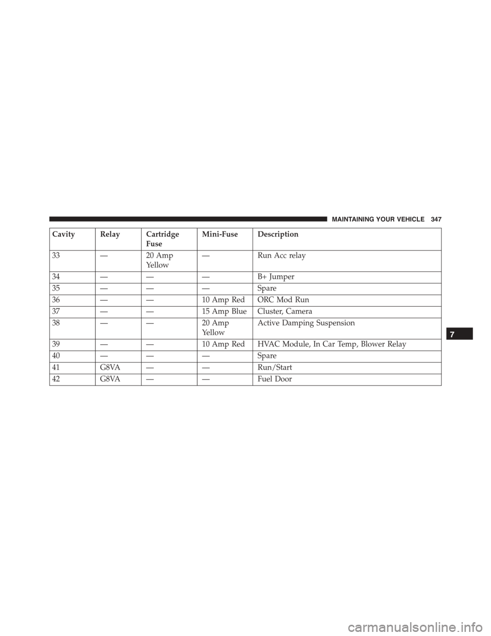
Active Damping Suspension
39——10 Amp Red HVAC Module, In Car Temp, Blower Relay
40———Spare
41G8VA ——Run/Start
42G8VA ——Fuel Door
7
MAINTAINING YOUR VEHICLE 347
Page 365 of 400
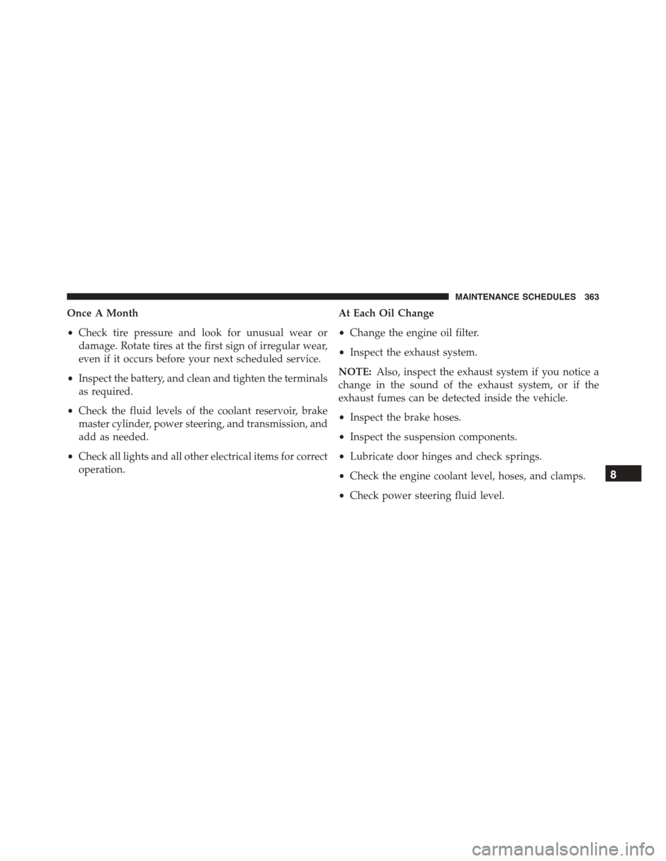
Once A Month
•Check tire pressure and look for unusual wear or
damage. Rotate tires at the first sign of irregular wear,
even if it occurs before your next scheduled service.
•Inspect the battery, and clean and tighten the terminals
as required.
•Check the fluid levels of the coolant reservoir, brake
master cylinder, power steering, and transmission, and
add as needed.
•Check all lights and all other electrical items for correct
operation.
At Each Oil Change
•Change the engine oil filter.
•Inspect the exhaust system.
NOTE:Also, inspect the exhaust system if you notice a
change in the sound of the exhaust system, or if the
exhaust fumes can be detected inside the vehicle.
•Inspect the brake hoses.
•Inspect the suspension components.
•Lubricate door hinges and check springs.
•Check the engine coolant level, hoses, and clamps.
•Check power steering fluid level.
8
MAINTENANCE SCHEDULES 363
Page 367 of 400
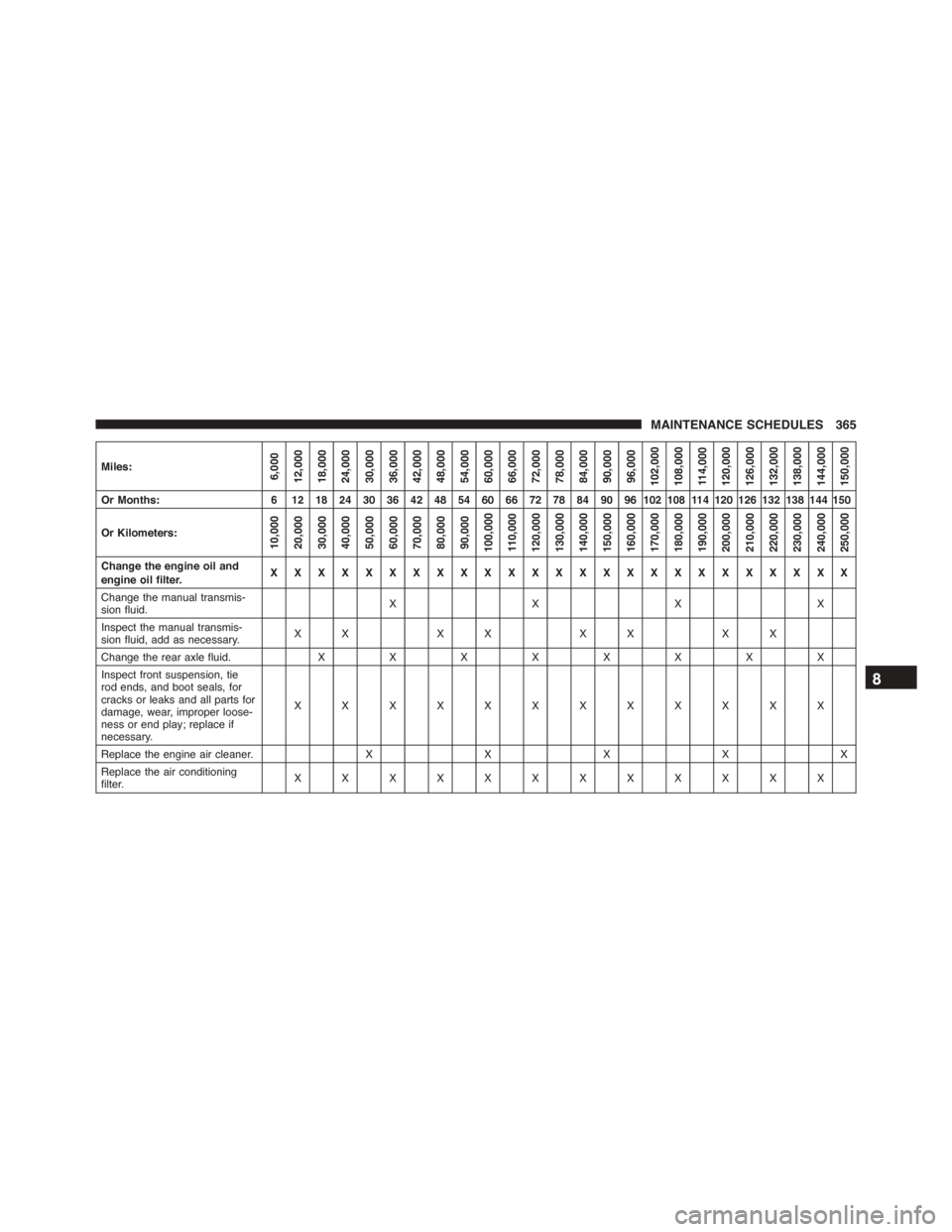
Miles:6,00012,00018,00024,00030,00036,00042,00048,00054,00060,00066,00072,00078,00084,00090,00096,000102,000108,00011 4 , 0 0 0120,000126,000132,000138,000144,000150,000
Or Months:6121824303642485460667278849096102108114120126132138144150
Or Kilometers:10,00020,00030,00040,00050,00060,00070,00080,00090,000100,00011 0 , 0 0 0120,000130,000140,000150,000160,000170,000180,000190,000200,000210,000220,000230,000240,000250,000
Change the engine oil andengine oil filter.XXXXXXXXXXXXXXXXXXXXXXXXX
Change the manual transmis-sion fluid.XXXX
Inspect the manual transmis-sion fluid, add as necessary.XX XX XX XX
Change the rear axle fluid.XXXXXXXX
Inspect front suspension, tierod ends, and boot seals, forcracks or leaks and all parts fordamage, wear, improper loose-ness or end play; replace ifnecessary.
XXXXXXXXXXXX
Replace the engine air cleaner.XXXXX
Replace the air conditioningfilter.XXXXXXXXXXXX
8
MAINTENANCE SCHEDULES 365