transmission DODGE VIPER 2015 VX / 3.G User Guide
[x] Cancel search | Manufacturer: DODGE, Model Year: 2015, Model line: VIPER, Model: DODGE VIPER 2015 VX / 3.GPages: 148, PDF Size: 21.7 MB
Page 3 of 148
INTRODUCTION/WELCOME
WELCOME FROM FCA US LLC.......2
CONTROLS AT A GLANCE
DRIVER COCKPIT...............4INSTRUMENT CLUSTER...........6
GETTING STARTED
KEY FOB . . . . . . . . . . . . . . . . . . . . . 8ENGINE STARTING/STOPPING.......9VEHICLE SECURITY ALARM........10SEAT BELT SYSTEMS............11SUPPLEMENTAL RESTRAINTSYSTEM (SRS) — AIR BAGS........12CHILD RESTRAINTS............14NON-ADJUSTABLE HEAD RESTRAINTS...17FRONT SEATS................18ADJUSTABLE PEDALS...........19ADJUSTABLE FOOT REST..........20TILT STEERING COLUMN.........20
OPERATING YOUR VEHICLE
SRT ENGINE BREAK-INRECOMMENDATIONS............21TURN SIGNALS/WIPER/WASHER/HIGHBEAMS LEVER................22HEADLIGHT SWITCH............23ELECTRONIC SPEED CONTROL......24LAUNCH MODE................26ELECTRONIC CONTROL DAMPINGSYSTEM....................27ELECTRONIC STABILITY CONTROL(ESC)......................28MANUAL TRANSMISSION 1 TO 4 SKIPSHIFT.....................29ADDING FUEL................30AUTOMATIC TEMPERATURECONTROL (ATC)...............33PA R K V I E W®REAR BACK-UP CAMERA...35
ELECTRONICS
YOUR VEHICLE'S SOUND SYSTEM....36YOUR RADIO.................38Uconnect®ACCESS.............38Uconnect®8.4AN...............54Uconnect®8.4AN VOICE RECOGNITIONQUICK TIPS..................67Uconnect®PHONE..............82STEERING WHEEL AUDIO CONTROLS . . . 90DRIVER INFORMATION DISPLAY (DID) . . . 91PERFORMANCE PAGES...........93PROGRAMMABLE FEATURES.......94UNIVERSAL GARAGE DOOR OPENER(HomeLink®).................94POWER OUTLETS..............97
UTILITY
TRAILER TOWING WEIGHTS(MAXIMUM TRAILER WEIGHTRATINGS)...................98RECREATIONAL TOWING(BEHIND MOTORHOME, ETC.)......98
WHAT TO DO IN EMERGENCIES
ROADSIDE ASSISTANCE..........99INSTRUMENT CLUSTER WARNINGLIGHTS....................99INSTRUMENT CLUSTER INDICATORLIGHTS...................103IF YOUR ENGINE OVERHEATS......104TIRE SERVICE KIT.............105JUMP-STARTING..............111TOWING A DISABLED VEHICLE.....113FREEING A STUCK VEHICLE.......113EVENT DATA RECORDER (EDR).....114
MAINTAINING YOUR VEHICLE
OPENING THE HOOD...........115ENGINE COMPARTMENT.........116FLUID CAPACITIES............118FLUIDS, LUBRICANTS, ANDGENUINE PARTS..............118MAINTENANCE PROCEDURES......119MAINTENANCE SCHEDULES......120SRT – MAINTENANCE RECORD.....123FUSES....................124SUMMER/THREE-SEASON TIRES....126TIRE PRESSURES.............127SPARE TIRES — IF EQUIPPED......127WHEEL AND WHEEL TRIM CARE....129EXTERIOR BULBS.............129
CONSUMER ASSISTANCE
FCA US LLC CUSTOMER CENTER....130FCA CANADA INC. CUSTOMERCENTER...................130ASSISTANCE FOR THE HEARINGIMPAIRED..................130PUBLICATIONS ORDERING........130REPORTING SAFETY DEFECTS INTHE UNITED STATES............131
MOPAR® ACCESSORIES
AUTHENTIC ACCESSORIESBY MOPAR®.................132
FREQUENTLY ASKED QUESTIONS
FREQUENTLY ASKED QUESTIONS....133
INDEX.....................134
TABLE OF CONTENTS
Page 5 of 148
VEHICLES SOLD IN CANADA
With respect to any vehicles sold in Canada, the name FCA US LLC shall be deemed to be
deleted and the name FCA Canada Inc. used in substitution (excluding legal lines).
WARNING!
•Pedalsthatcannotmovefreelycancauselossofvehiclecontrolandincreasethe
risk of serious personal injury.
•Alwaysmakesurethatobjectscannotfallintothedriverfootwellwhilethevehicle
is moving. Objects can become trapped under the brake pedal and accelerator
pedal causing a loss of vehicle control.
•Failuretoproperlyfollowfloormatinstallationormountingcancauseinterference
with the brake pedal and accelerator pedal operation causing loss of control of the
vehicle.
•Never leave children alone in a vehicle, or with access to an unlocked vehicle. Allowing
children to be in a vehicle unattended is dangerous for a number of reasons. A child or
others could be seriously or fatally injured. Children should be warned not to touch the
parking brake, brake pedal or the shift lever/transmission gear selector.
•Do not leave the key fob in or near the vehicle, or in a location accessible to children,
and do not leave the ignition of a vehicle equipped with Keyless Enter-N-Go™ in the
ACC or ON/RUN mode. A child could operate power windows, other controls, or move
the vehicle.
•Neverusethe“PARK”positionasasubstitutefortheparkingbrake.Alwaysapply
the parking brake fully when parked to guard against vehicle movement and
possible injury or damage.
•RefertoyourOwner'sManualontheDVDforfurtherdetails.
USE OF AFTERMARKET PRODUCTS (ELECTRONICS)
The use of aftermarket devices including cell phones, MP3 players, GPS systems, or
chargers may affect the performance of on-board wireless features including Keyless
Enter-N-Go™ and Remote Start range. If you are experiencing difficulties with any of your
wireless features, try disconnecting your aftermarket devices to see if the situation
improves. If your symptoms persist, please see an authorized dealer.
CHRYSLER, DODGE, JEEP, RAM, MOPAR and Uconnect are registered trademarks of
FCA US LLC.
COPYRIGHT ©2015 FCA US LLC
INTRODUCTION/WELCOME
3
Page 11 of 148
WARNING!
•Alwaysapplytheparkingbrakefullywhenparkedtoguardagainstvehiclemove-
ment and possible injury or damage.
•Never leave children alone in a vehicle, or with access to an unlocked vehicle. Allowing
children to be in a vehicle unattended is dangerous for a number of reasons. A child or
others could be seriously or fatally injured. Children should be warned not to touch the
parking brake, brake pedal or the transmission gear selector.
•Do not leave the Key Fob in or near the vehicle, or in a location accessible to children,
and do not leave the ignition of a vehicle equipped with Keyless Enter-N-Go™ in the
ACC or ON/RUN mode. A child could operate power windows, other controls, or move
the vehicle.
ENGINE STARTING/STOPPING
Starting
1. Fully apply the parking brake.
2. Push the clutch pedal to the floor.
3. Place the shift lever in NEUTRAL.
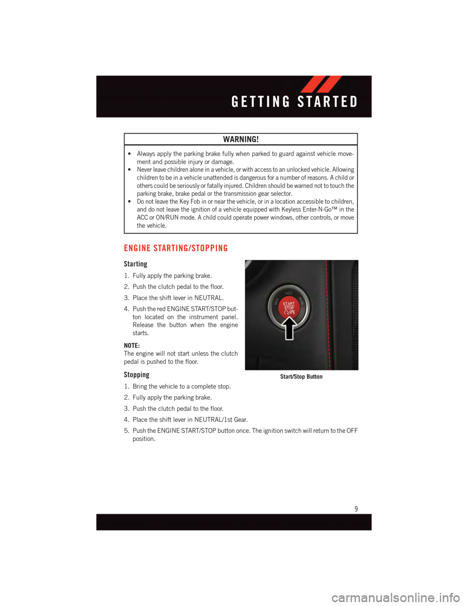
4. Push the red ENGINE START/STOP but-
ton located on the instrument panel.
Release the button when the engine
starts.
NOTE:
The engine will not start unless the clutch
pedal is pushed to the floor.
Stopping
1. Bring the vehicle to a complete stop.
2. Fully apply the parking brake.
3. Push the clutch pedal to the floor.
4. Place the shift lever in NEUTRAL/1st Gear.
5. Push the ENGINE START/STOP button once. The ignition switch will return to the OFF
position.
Start/Stop Button
GETTING STARTED
9
Page 31 of 148
Rain Mode
•Rainmodeoffersincreasedtractioncontrolandstabilitycontrolforlowtraction
conditions such as wet roads, dry roads during cold temperatures, or when the driver
wants enhanced stability due to lack of familiarity or experience with the vehicle’s
response. To enter the “Rain Mode” mode, push the “ESC” switch three times. The
“ESC RAIN” light will illuminate, and the “ESC RAIN” message will display in the
vehicle cluster (left of the odometer).
NOTE:
Some models may not offer “Sport” or “Track” Mode.
WARNING!
The Electronic Stability Control System (ESC) cannot prevent the natural laws of physics
from acting on the vehicle, nor can it increase the traction afforded by prevailing road
conditions. ESC cannot prevent all accidents, including those resulting from excessive
speed in turns, driving on very slippery surfaces, or hydroplaning. ESC also cannot
prevent accidents resulting from loss of vehicle control due to inappropriate driver input
for the conditions. Only a safe, attentive, and skillful driver can prevent accidents. The
capabilities of an ESC equipped vehicle must never be exploited in a reckless or
dangerous manner which could jeopardize the user’s safety or the safety of others.
MANUAL TRANSMISSION 1 TO 4 SKIP SHIFT
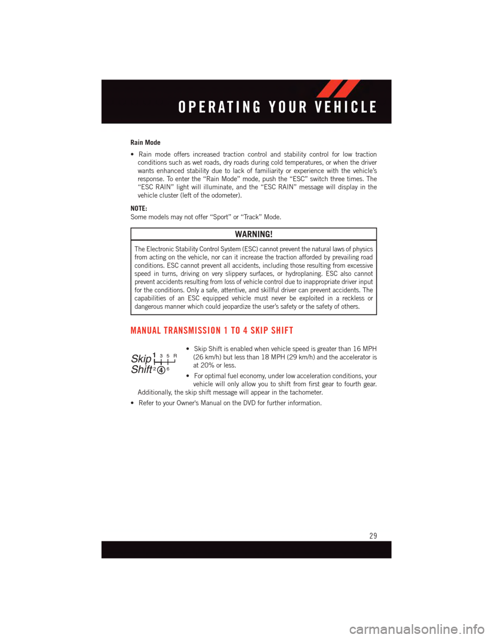
•SkipShiftisenabledwhenvehiclespeedisgreaterthan16MPH
(26 km/h) but less than 18 MPH (29 km/h) and the accelerator is
at 20% or less.
•Foroptimalfueleconomy,underlowaccelerationconditions,your
vehicle will only allow you to shift from first gear to fourth gear.
Additionally, the skip shift message will appear in the tachometer.
•RefertoyourOwner'sManualontheDVDforfurtherinformation.
Skip
Shift
133
22
55RR
6
OPERATING YOUR VEHICLE
29
Page 96 of 148
PROGRAMMABLE FEATURES
Uconnect® Customer Programmable Features
The Uconnect®system allows you to access Customer Programmable feature settings
such as Display, Voice, Clock, Safety & Driving Assistance, Lights, Doors & Locks, Engine
Off Options, Audio, Phone / Bluetooth, SiriusXM Setup, Restore Settings, Clear Personal
Data, and System Information through buttons on the touchscreen.
•Pressthe“SRT&Apps”buttononthetouchscreen,thenpressthe“Settings”button
on the touchscreen to access the Settings screen. When making a selection, scroll up
or down until the preferred setting is highlighted, then press and release the preferred
setting until a check-mark appears next to the setting, showing that setting has been
selected. The following feature settings are available:
•Display•Audio
•Voice•Phone/Bluetooth
•Clock•SiriusXMSetup
•Safety&DrivingAssistance•RestoreSettings
•Lights•ClearPersonalData
•Doors&Locks•SystemInformation
•EngineOffOptions
UNIVERSAL GARAGE DOOR OPENER (HomeLink®)
HomeLink®replaces up to three hand-held transmitters that operate devices such as
garage door openers, motorized gates, lighting or home security systems. The HomeLink®
unit is powered by your vehicles 12 Volt battery.
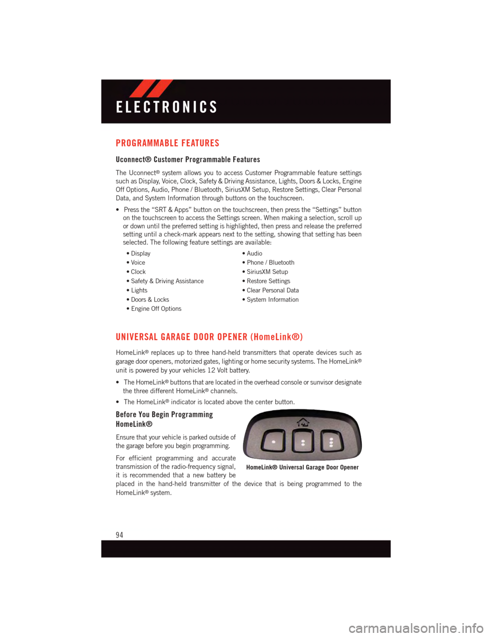
•TheHomeLink®buttons that are located in the overhead console or sunvisor designate
the three different HomeLink®channels.
•TheHomeLink®indicator is located above the center button.
Before You Begin Programming
HomeLink®
Ensure that your vehicle is parked outside of
the garage before you begin programming.
For efficient programming and accurate
transmission of the radio-frequency signal,
it is recommended that a new battery be
placed in the hand-held transmitter of the device that is being programmed to the
HomeLink®system.
HomeLink® Universal Garage Door Opener
ELECTRONICS
94
Page 100 of 148
TRAILER TOWING WEIGHTS (MAXIMUM TRAILER WEIGHT
RATINGS)
Tr a i l e r t o w i n g w i t h t h i s v e h i c l e i s n o t r e c o m m e n d e d .
RECREATIONAL TOWING (BEHIND MOTORHOME, ETC.)
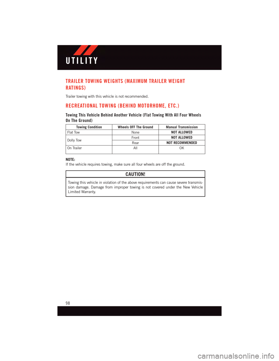
Towing This Vehicle Behind Another Vehicle (Flat Towing With All Four Wheels
On The Ground)
Towing Condition Wheels OFF The Ground Manual Transmission
Flat TowNoneNOT ALLOWED
Dolly TowFrontNOT ALLOWED
RearNOT RECOMMENDED
On TrailerAllOK
NOTE:
If the vehicle requires towing, make sure all four wheels are off the ground.
CAUTION!
To w i n g t h i s v e h i c l e i n v i o l a t i o n o f t h e a b o v e r e q u i r e m e n t s c a n c a u s e s e v e r e t r a n s m i s -
sion damage. Damage from improper towing is not covered under the New Vehicle
Limited Warranty.
UTILITY
98
Page 103 of 148
When the system detects a malfunction, the telltale will flash for approximately one
minute and then remain continuously illuminated. This sequence will continue upon
subsequent vehicle start-ups as long as the malfunction exists. When the malfunction
indicator is illuminated, the system may not be able to detect or signal low tire pressure
as intended. TPMS malfunctions may occur for a variety of reasons, including the
installation of replacement or alternate tires or wheels on the vehicle that prevent the
TPMS from functioning properly. Always check the TPMS malfunction telltale after
replacing one or more tires or wheels on your vehicle to ensure that the replacement or
alternate tires and wheels allow the TPMS to continue to function properly.
NOTE:
Ti r e p r e s s u r e s c h a n g e b y a p p r o x i m a t e l y 1 p s i ( 7 k P a ) p e r 1 2 ° F ( 7 ° C ) o f a i r t e m p e r a t u r e
change. Keep this in mind when checking tire pressure inside a garage, especially in the
Winter. Example: If garage temperature is 68°F (20°C), and the outside temperature is
32°F (0°C), then the cold tire inflation pressure should be increased by 3 psi (21 kPa),
which equals 1 psi (7 kPa) for every 12°F (7°C) for this outside temperature condition.
CAUTION!
The TPMS has been optimized for the original equipment tires and wheels. TPMS
pressures and warning have been established for the tire size equipped on your vehicle.
Undesirable system operation or sensor damage may result when using replacement
equipment that is not of the same size, type, and/or style. Aftermarket wheels can
cause sensor damage. Do not use tire sealant from a can, or balance beads if your
vehicle is equipped with a TPMS, as damage to the sensors may result.
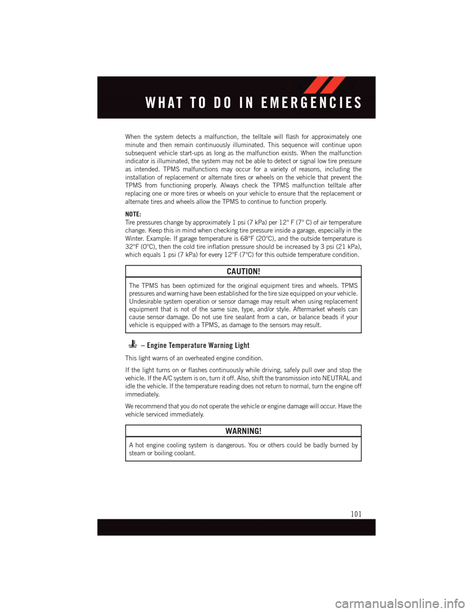
–EngineTemperatureWarningLight
This light warns of an overheated engine condition.
If the light turns on or flashes continuously while driving, safely pull over and stop the
vehicle. If the A/C system is on, turn it off. Also, shift the transmission into NEUTRAL and
idle the vehicle. If the temperature reading does not return to normal, turn the engine off
immediately.
We recommend that you do not operate the vehicle or engine damage will occur. Have the
vehicle serviced immediately.
WARNING!
Ahotenginecoolingsystemisdangerous.Youorotherscouldbebadlyburnedby
steam or boiling coolant.
WHAT TO DO IN EMERGENCIES
101
Page 106 of 148
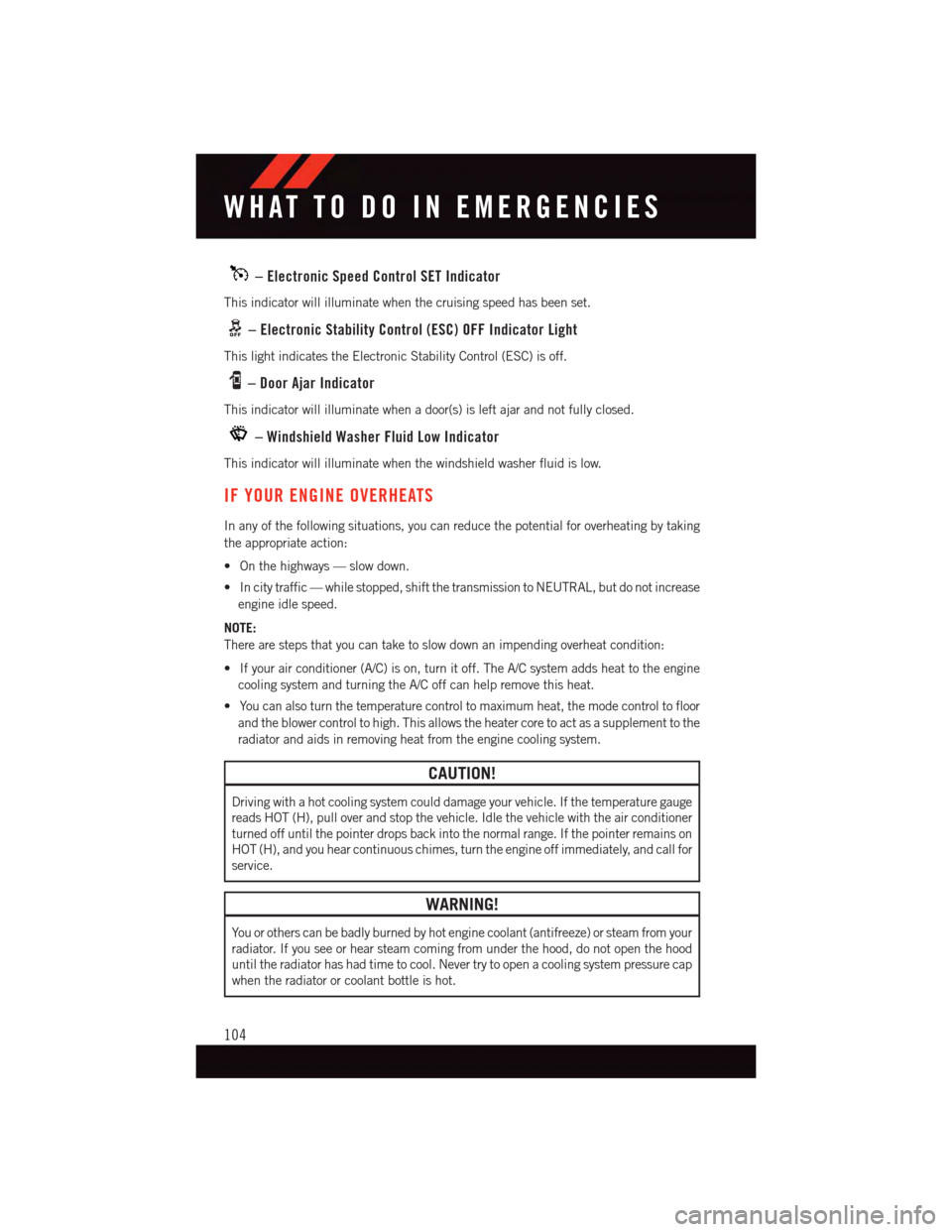
–ElectronicSpeedControlSETIndicator
This indicator will illuminate when the cruising speed has been set.
–ElectronicStabilityControl(ESC)OFFIndicatorLight
This light indicates the Electronic Stability Control (ESC) is off.
–DoorAjarIndicator
This indicator will illuminate when a door(s) is left ajar and not fully closed.
–WindshieldWasherFluidLowIndicator
This indicator will illuminate when the windshield washer fluid is low.
IF YOUR ENGINE OVERHEATS
In any of the following situations, you can reduce the potential for overheating by taking
the appropriate action:
•Onthehighways—slowdown.
•Incitytraffic—whilestopped,shiftthetransmissiontoNEUTRAL,butdonotincrease
engine idle speed.
NOTE:
There are steps that you can take to slow down an impending overheat condition:
•Ifyourairconditioner(A/C)ison,turnitoff.TheA/Csystemaddsheattotheengine
cooling system and turning the A/C off can help remove this heat.
•Youcanalsoturnthetemperaturecontroltomaximumheat,themodecontroltofloor
and the blower control to high. This allows the heater core to act as a supplement to the
radiator and aids in removing heat from the engine cooling system.
CAUTION!
Driving with a hot cooling system could damage your vehicle. If the temperature gauge
reads HOT (H), pull over and stop the vehicle. Idle the vehicle with the air conditioner
turned off until the pointer drops back into the normal range. If the pointer remains on
HOT (H), and you hear continuous chimes, turn the engine off immediately, and call for
service.
WARNING!
Yo u o r o t h e r s c a n b e b a d l y b u r n e d b y h o t e n g i n e c o o l a n t ( a n t i f r e e z e ) o r s t e a m f r o m y o u r
radiator. If you see or hear steam coming from under the hood, do not open the hood
until the radiator has had time to cool. Never try to open a cooling system pressure cap
when the radiator or coolant bottle is hot.
WHAT TO DO IN EMERGENCIES
104
Page 108 of 148
Tire Service Kit Usage Precautions
•ReplacetheTireServiceKitSealantBottle(1)andSealantHose(6)priortothe
expiration date (printed on the bottle label) to assure optimum operation of the system.
Refer to “Sealing A Tire With Tire Service Kit” section (F) “Sealant Bottle and Hose
Replacement.”
•TheSealantBottle(1)andSealantHose(6)areaonetireapplicationuse.Aftereach
use, always replace these components immediately at an authorized dealer.
•WhentheTireServiceKitsealantisinaliquidform,cleanwater,andadampclothwill
remove the material from the vehicle or tire and wheel components. Once the sealant
dries, it can easily be peeled off and properly discarded.
•Foroptimumperformance,makesurethevalvestemonthewheelisfreeofdebris
before connecting the Tire Service Kit.
•YoucanusetheTireServiceKitairpumptoinflatebicycletires.Thekitalsocomeswith
two needles, located in the Accessory Storage Compartment (on the bottom of the air
pump) for inflating sport balls, rafts, or similar inflatable items. However, use only the
Air Pump Hose (7) and make sure the Mode Select Knob (5) is in the Air Mode when
inflating such items to avoid injecting sealant into them. The Tire Service Kit Sealant is
only intended to seal punctures less than 1/4 inch (6 mm) diameter in the tread of your
vehicle.
•DonotliftorcarrytheTireServiceKitbythehoses.
Sealing A Tire With Tire Service Kit
(A) Whenever You Stop To Use Tire Service Kit:
1. Pull over to a safe location and turn on the vehicle’s Hazard Warning flashers.
2. Verify that the valve stem (on the wheel with the deflated tire) is in a position that is
near to the ground. This will allow the Tire Service Kit Hoses (6) and (7) to reach the
valve stem and keep the Tire Service Kit flat on the ground. This will provide the best
positioning of the kit when injecting the sealant into the deflated tire and running the
air pump. Move the vehicle as necessary to place the valve stem in this position before
proceeding.
3. Place the transmission in PARK (auto transmission) or in Gear (manual transmission)
and cycle the ignition to the OFF position.
4. Set the parking brake.
(B) Setting Up To Use Tire Service Kit:
1. Turn the Mode Select Knob (5) to the Sealant Mode position.
2. Uncoil the Sealant Hose (6) and then remove the cap from the fitting at the end of the
hose.
3. Place the Tire Service Kit flat on the ground next to the deflated tire.
WHAT TO DO IN EMERGENCIES
106
Page 109 of 148
4. Remove the cap from the valve stem and then screw the fitting at the end of the
Sealant Hose (6) onto the valve stem.
5. Uncoil the Power Plug (8) and insert the plug into the vehicle’s 12 Volt power outlet.
6. Do not remove foreign objects (e.g., screws or nails) from the tire.
(C) Injecting Tire Service Kit Sealant Into The Deflated Tire:
Always start the engine before turning ON the Tire Service Kit.
NOTE:
Manual transmission vehicles must have the parking brake engaged and the shift lever in
NEUTRAL.
After pushing the Power Button (4), the sealant (white fluid) will flow from the Sealant
Bottle (1) through the Sealant Hose (6) and into the tire.
NOTE:
Sealant may leak out through the puncture in the tire.
If the sealant (white fluid) does not flow within0–10seconds through the Sealant Hose (6):
1. Push the Power Button (4) to turn Off the Tire Service Kit. Disconnect the Sealant Hose
(6) from the valve stem. Make sure the valve stem is free of debris. Reconnect the
Sealant Hose (6) to the valve stem. Check that the Mode Select Knob (5) is in the
Sealant Mode position and not Air Mode. Push the Power Button (4) to turn On the Tire
Service Kit.
2. Connect the Power Plug (8) to a different 12 Volt power outlet in your vehicle or
another vehicle, if available. Make sure the engine is running before turning ON the
Ti r e S e r v i c e K i t .
3. The Sealant Bottle (1) may be empty due to previous use. Call for assistance.
NOTE:
If the Mode Select Knob (5) is on Air Mode and the pump is operating, air will dispense
from the Air Pump Hose (7) only, not the Sealant Hose (6).
If the sealant (white fluid) does flow through the Sealant Hose (6):
1. Continue to operate the pump until sealant is no longer flowing through the hose
(typically takes 30 - 70 seconds). As the sealant flows through the Sealant Hose (6),
the Pressure Gauge (3) can read as high as 70 psi (4.8 Bar). The Pressure Gauge (3)
will decrease quickly from approximately 70 psi (4.8 Bar) to the actual tire pressure
when the Sealant Bottle (1) is empty.
2. The pump will start to inject air into the tire immediately after the Sealant Bottle (1)
is empty. Continue to operate the pump and inflate the tire to the pressure indicated
on the tire pressure label on the driver-side latch pillar (recommended pressure).
Check the tire pressure by looking at the Pressure Gauge (3).
WHAT TO DO IN EMERGENCIES
107