torque FIAT 127 1979 2.G Workshop Manual
[x] Cancel search | Manufacturer: FIAT, Model Year: 1979, Model line: 127, Model: FIAT 127 1979 2.GPages: 34, PDF Size: 6.87 MB
Page 15 of 34
Fiat 127 Internet Fan Club (http://fiat127.okruhy.cz) Fiat 127 - 1050
15/34
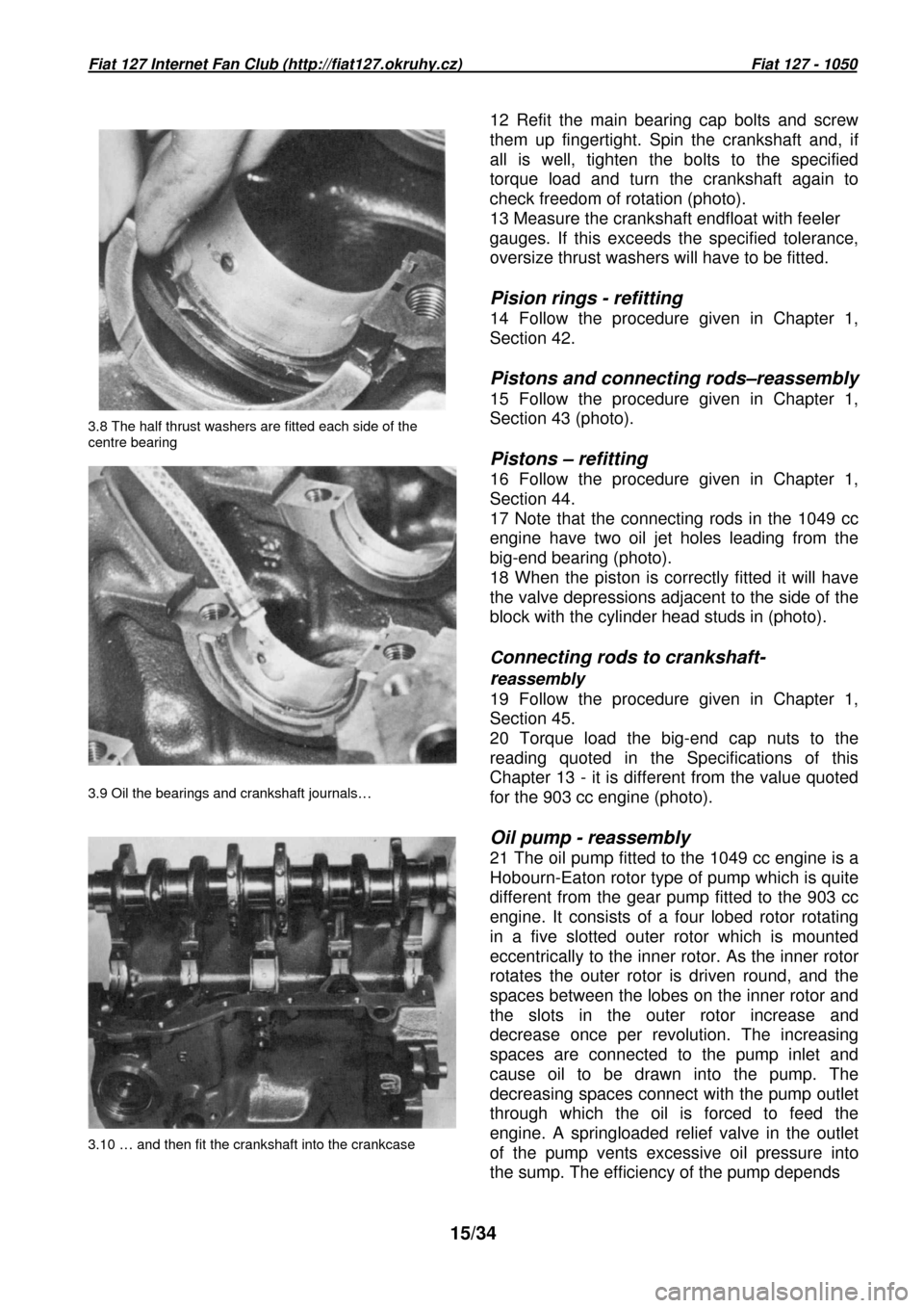
3.8 The half thrust washers are fitted each side of
the
centre bearing
3.9 Oil the bearings and crankshaft journals…
3.10 … and then fit the crankshaft into the crankca se 12 Refit the main bearing cap bolts and screw
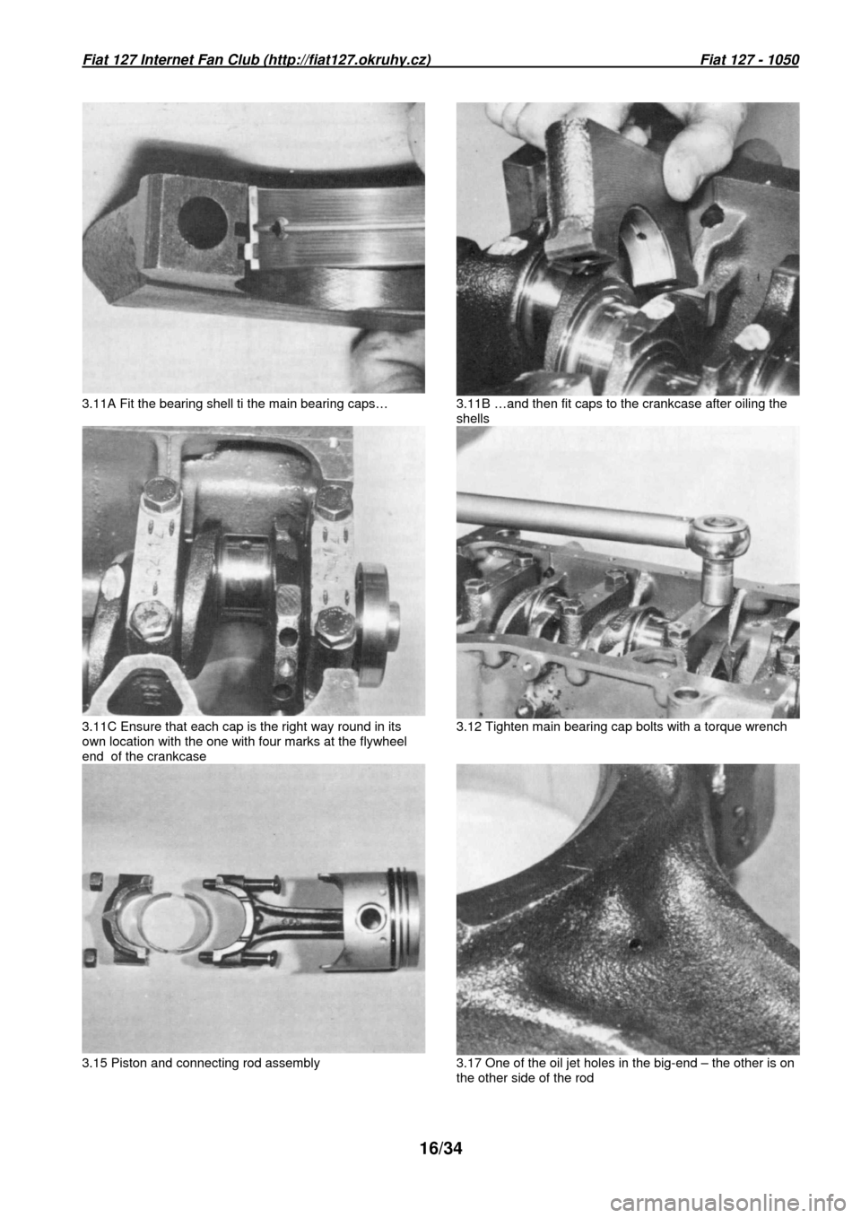
them up fingertight. Spin the crankshaft and, if
all is well, tighten the bolts to the specified
torque load and turn the crankshaft again to
check freedom of rotation (photo).
13 Measure the crankshaft endfloat with feeler
gauges. If this exceeds the specified tolerance,
oversize thrust washers will have to be fitted.
Pision rings - refitting
14 Follow the procedure given in Chapter 1,
Section 42.
Pistons and connecting rods–reassembly
15 Follow the procedure given in Chapter 1,
Section 43 (photo).
Pistons – refitting
16 Follow the procedure given in Chapter 1,
Section 44.
17 Note that the connecting rods in the 1049 cc
engine have two oil jet holes leading from the
big-end bearing (photo).
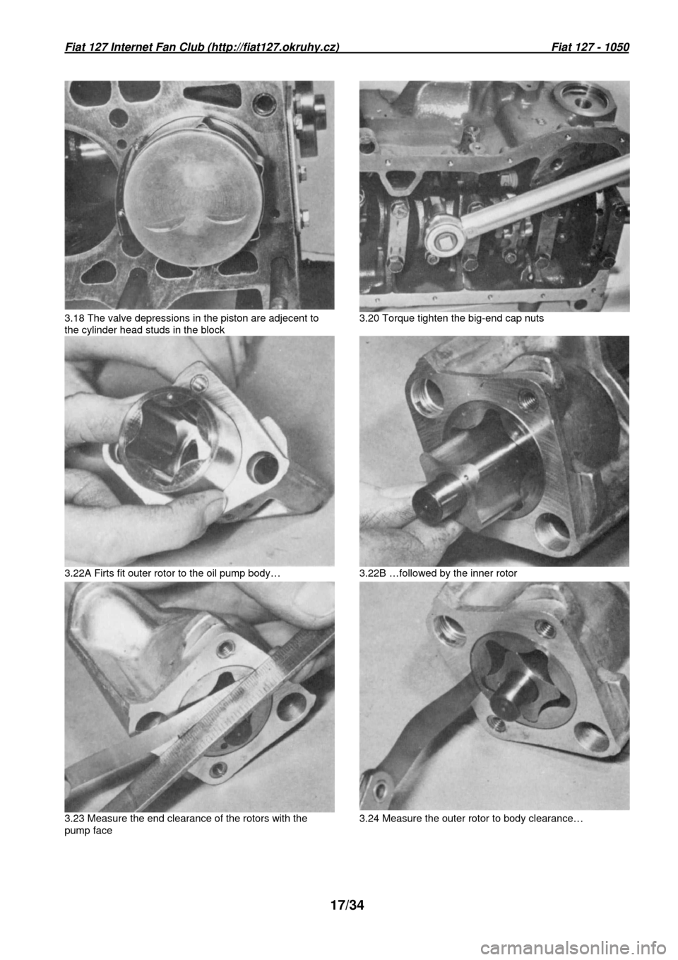
18 When the piston is correctly fitted it will have
the valve depressions adjacent to the side of the
block with the cylinder head studs in (photo). C
onnecting rods to crankshaft-
r
eassembly
19 Follow the procedure given in Chapter 1,
Section 45.
20 Torque load the big-end cap nuts to the
reading quoted in the Specifications of this
Chapter 13 - it is different from the value quoted
for the 903 cc engine (photo).
Oil pump - reassembly
21 The oil pump fitted to the 1049 cc engine is a
Hobourn-Eaton rotor type of pump which is quite
different from the gear pump fitted to the 903 cc
engine. It consists of a four lobed rotor rotating
in a five slotted outer rotor which is mounted
eccentrically to the inner rotor. As the inner roto r
rotates the outer rotor is driven round, and the
spaces between the lobes on the inner rotor and
the slots in the outer rotor increase and
decrease once per revolution. The increasing
spaces are connected to the pump inlet and
cause oil to be drawn into the pump. The
decreasing spaces connect with the pump outlet
through which the oil is forced to feed the
engine. A springloaded relief valve in the outlet
of the pump vents excessive oil pressure into
the sump. The efficiency of the pump depends
Page 16 of 34
Fiat 127 Internet Fan Club (http://fiat127.okruhy.cz) Fiat 127 - 1050
16/34
3.11A Fit the bearing shell ti the main bearing cap s… 3.11B …and then fit caps to the crankcase after oil ing the
shells
3.11C Ensure that each cap is the right way round i n its
own location with the one with four marks at the fl ywheel
end of the crankcase 3.12 Tighten main bearing cap bolts with a torque w rench
3.15 Piston and connecting rod assembly 3.17 One of the oil jet holes in the big-end – the other is on
the other side of the rod
Page 17 of 34
Fiat 127 Internet Fan Club (http://fiat127.okruhy.cz) Fiat 127 - 1050
17/34
3.18 The valve depressions in the piston are adjece nt to
the cylinder head studs in the block 3.20 Torque tighten the big-end cap nuts
3.22A Firts fit outer rotor to the oil pump body… 3.22B …followed by the inner rotor
3.23 Measure the end clearance of the rotors with t he
pump face 3.24 Measure the outer rotor to body clearance…
Page 19 of 34
Fiat 127 Internet Fan Club (http://fiat127.okruhy.cz) Fiat 127 - 1050
19/34
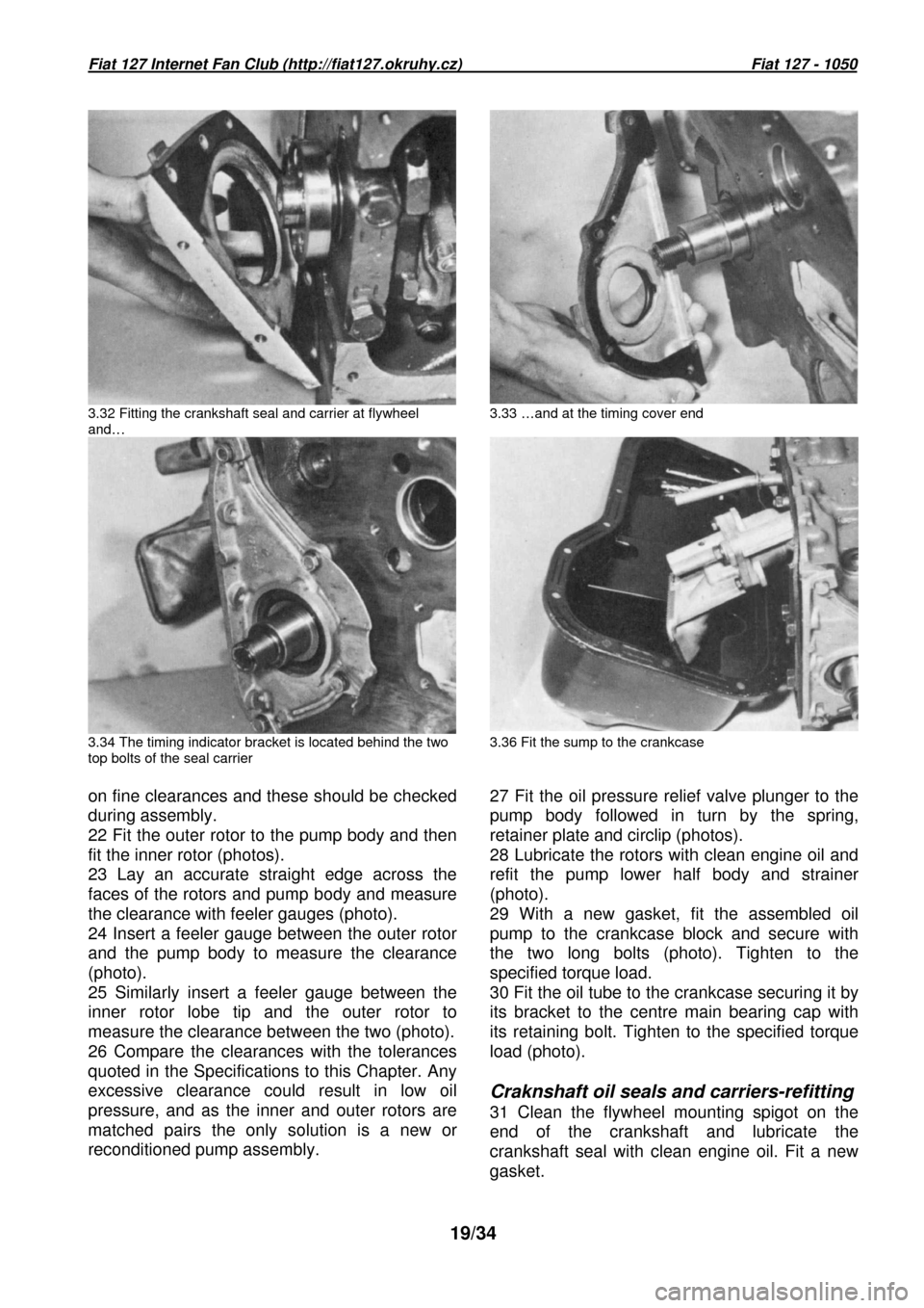
3.32 Fitting the crankshaft seal and carrier at fly wheel
and… 3.33 …and at the timing cover end
3.34 The timing indicator bracket is located behind the two
top bolts of the seal carrier 3.36 Fit the sump to the crankcase
on fine clearances and these should be checked
during assembly.
22 Fit the outer rotor to the pump body and then
fit the inner rotor (photos).
23 Lay an accurate straight edge across the
faces of the rotors and pump body and measure
the clearance with feeler gauges (photo).
24 Insert a feeler gauge between the outer rotor
and the pump body to measure the clearance
(photo).
25 Similarly insert a feeler gauge between the
inner rotor lobe tip and the outer rotor to
measure the clearance between the two (photo).
26 Compare the clearances with the tolerances
quoted in the Specifications to this Chapter. Any
excessive clearance could result in low oil
pressure, and as the inner and outer rotors are
matched pairs the only solution is a new or
reconditioned pump assembly. 27 Fit the oil pressure relief valve plunger to th
e
pump body followed in turn by the spring,
retainer plate and circlip (photos).
28 Lubricate the rotors with clean engine oil and
refit the pump lower half body and strainer
(photo).
29 With a new gasket, fit the assembled oil
pump to the crankcase block and secure with
the two long bolts (photo). Tighten to the
specified torque load.
30 Fit the oil tube to the crankcase securing it by
its bracket to the centre main bearing cap with
its retaining bolt. Tighten to the specified torque
load (photo).
Craknshaft oil seals and carriers-refitting
31 Clean the flywheel mounting spigot on the
end of the crankshaft and lubricate the
crankshaft seal with clean engine oil. Fit a new
gasket.
Page 24 of 34
Fiat 127 Internet Fan Club (http://fiat127.okruhy.cz) Fiat 127 - 1050
24/34
progressively until the bearing halves meet.
53 Oil the camshaft seal and carefully fit it with
its carrier and a new gasket to the cylinder head
(photo).
54 Position the drivebelt guard backplate over
the camshaft seal carrier and fit the three bolts
and washers (photo). 55 Tighten the three bolts
retaining the backplate and seal carrier. Torque
load the four camshaft bearing securing nuts to
the specified setting.
56 Fit the camshaft toothed driving pulley with its
bolt and washer. Leave the final tightening until
the drivebelt is fitted (photo).
57 Check the valve clearances; the camshaft
can be turned by a spanner on the pulley
retaining bolt. Readjust any clearance if
necessary, as described later in this Section.
58 Owing to the small clearance between a
piston at TDC and the open valves during
exhaust/inlet overlap, it is imperative to get the
crankshaft and camshaft in their correct related
positions before turning the engine after fitting
the cylinder head. If this relationship is out then
serious damage could be done to the valves or
pistons by turning the crankshaft, as the pistons
will impinge on the valve heads. To avoid this
the following sequence should be observed. Set
the crankshaft as described in paragraph 59,
and the camshaft (before assembling the
cylinder head to the block) also as described in
paragraph 59. Fit the head to the block taking
care not to disturb the set positions and, finally,
fit the toothed drivebelt. Then the crankshaft can
be turned with no likelihood of damage.
59 Set the crankshaft by using a spanner on the
pulley retaining nut and aligning the mark on the
pulley with the long pointer on the timing
indicator bracket. Then set the camshaft by
aligning the hole in the camshaft pulley with the
cast ridge on the top of the camshaft seal carrier
just behind the toothed pulley (photo).
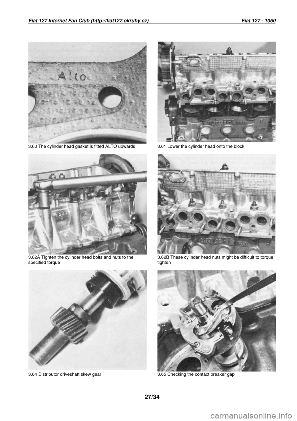
60 Fit a new cylinder head gasket with the word
ALTO upwards (photo). Do not use grease or
any other jointing compound. 61 Taking care not
to disturb the crankshaft or camshaft lower the
cylinder head onto the block (photo).
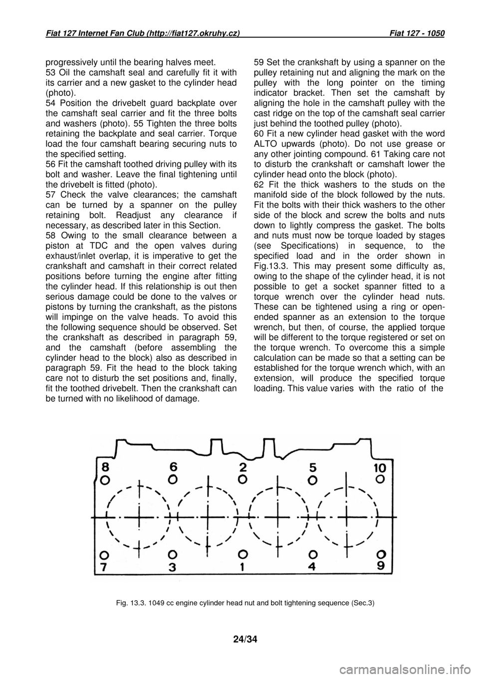
62 Fit the thick washers to the studs on the
manifold side of the block followed by the nuts.
Fit the bolts with their thick washers to the other
side of the block and screw the bolts and nuts
down to lightly compress the gasket. The bolts
and nuts must now be torque loaded by stages
(see Specifications) in sequence, to the
specified load and in the order shown in
Fig.13.3. This may present some difficulty as,
owing to the shape of the cylinder head, it is not
possible to get a socket spanner fitted to a
torque wrench over the cylinder head nuts.
These can be tightened using a ring or open-
ended spanner as an extension to the torque
wrench, but then, of course, the applied torque
will be different to the torque registered or set o n
the torque wrench. To overcome this a simple
calculation can be made so that a setting can be
established for the torque wrench which, with an
extension, will produce the specified torque
loading. This value varies with the ratio of t he
Fig. 13.3. 1049 cc engine cylinder head nut and bol t tightening sequence (Sec.3)
Page 26 of 34
Fiat 127 Internet Fan Club (http://fiat127.okruhy.cz) Fiat 127 - 1050
26/34
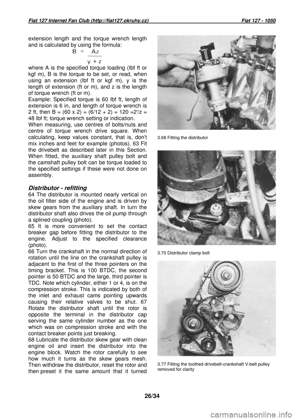
3.68 Fitting the distributor
3.70 Distributor clamp bolt
extension length and the torque wrench length
and is calculated by using the formula:
where A is the specified torque loading (Ibf ft or
kgf m), B is the torque to be set, or read, when
using an extension (Ibf ft or kgf m), y is the
length of extension (ft or m), and z is the length
of torque wrench (ft or m).
Example: Specified torque is 60 Ibf ft, length of
extension is 6 in, and length of torque wrench is
2 ft, then B = (60 x 2) = (6/12 + 2) = 120 =2'/z =
48 Ibf ft; torque wrench setting or indication.
When measuring, use centres of bolts/nuts and
centre of torque wrench drive square. When
calculating, keep values constant, that is, don't
mix inches and feet for example (photos). 63 Fit
the drivebelt as described later in this Section.
When fitted, the auxiliary shaft pulley bolt and
the camshaft pulley bolt can be torque loaded to
the specified settings if these were not done on
assembly.
Distributor - refitting
64 The distributor is mounted nearly vertical on
the oil filter side of the engine and is driven by
skew gears from the auxiliary shaft. In turn the
distributor shaft also drives the oil pump through
a splined coupling (photo).
65 It is more convenient to set the contact
breaker gap before fitting the distributor to the
engine. Adjust to the specified clearance
(photo).
66 Turn the crankshaft in the normal direction of
rotation until the line on the crankshaft pulley is
adjacent to the first of the three pointers on the
timing bracket. This is 100 BTDC, the second
pointer is 50 BTDC and the large, third pointer is
TDC. Note which cylinder, either 1 or 4, is on the
compression stroke. This is indicated by both of
the inlet and exhaust cams pointing upwards
causing their relative valves to be shut. 67
Rotate the distributor shaft until the rotor is
opposite the terminal in the distributor cap
serving the same cylinder number as the one
which was on compression stroke and with the
contact breaker points just breaking.
68 Lubricate the distributor skew gear with clean
engine oil and insert the distributor into the
engine block. Watch the rotor carefully to see
how much it turns as the skew gears mesh.
Then withdraw the distributor, reset the rotor and
then preset it the same amount that it turne d
3.77 Fitting the toothed drivebelt-crankshaft V-bel t pulley
removed for clarity
Page 27 of 34
Fiat 127 Internet Fan Club (http://fiat127.okruhy.cz) Fiat 127 - 1050
27/34
3.60 The cylinder head gasket is fitted ALTO upward s 3.61 Lower the cylinder head onto the block
3.62A Tighten the cylinder head bolts and nuts to t he
specified torque 3.62B These cylinder head nuts might be difficult
to torque
tighten
3.64 Distributor driveshaft skew gear 3.65 Checkin g the contact breaker gap
Page 28 of 34
Fiat 127 Internet Fan Club (http://fiat127.okruhy.cz) Fiat 127 - 1050
28/34
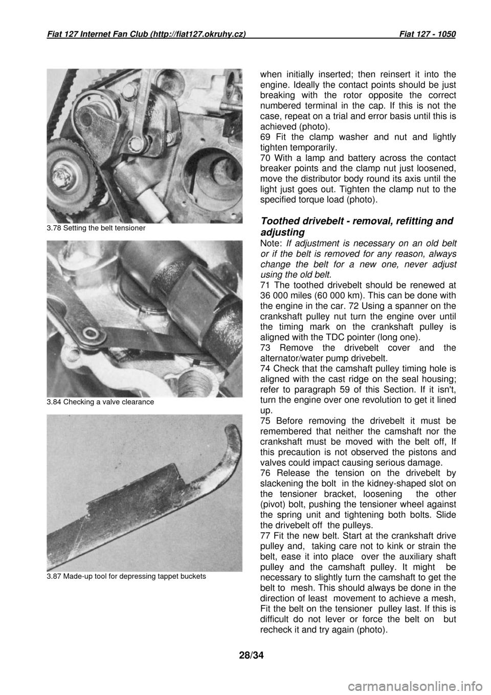
3.78 Setting the belt tensioner
3.84 Checking a valve clearance
3.87 Made-up tool for depressing tappet buckets
when initially inserted; then reinsert it into the
engine. Ideally the contact points should be just
breaking with the rotor opposite the correct
numbered terminal in the cap. If this is not the
case, repeat on a trial and error basis until this
is
achieved (photo).
69 Fit the clamp washer and nut and lightly
tighten temporarily.
70 With a lamp and battery across the contact
breaker points and the clamp nut just loosened,
move the distributor body round its axis until the
light just goes out. Tighten the clamp nut to the
specified torque load (photo).
Toothed drivebelt - removal, refitting and
adjusting
Note: If adjustment is necessary on an old belt
or if the belt is removed for any reason, always
change the belt for a new one, never adjust
using the old belt.
71 The toothed drivebelt should be renewed at
36 000 miles (60 000 km). This can be done with
the engine in the car. 72 Using a spanner on the
crankshaft pulley nut turn the engine over until
the timing mark on the crankshaft pulley is
aligned with the TDC pointer (long one).
73 Remove the drivebelt cover and the
alternator/water pump drivebelt.
74 Check that the camshaft pulley timing hole is
aligned with the cast ridge on the seal housing;
refer to paragraph 59 of this Section. If it isn't,
turn the engine over one revolution to get it lined
up.
75 Before removing the drivebelt it must be
remembered that neither the camshaft nor the
crankshaft must be moved with the belt off, If
this precaution is not observed the pistons and
valves could impact causing serious damage.
76 Release the tension on the drivebelt by
slackening the bolt in the kidney-shaped slot on
the tensioner bracket, loosening the other
(pivot) bolt, pushing the tensioner wheel against
the spring unit and tightening both bolts. Slide
the drivebelt off the pulleys.
77 Fit the new belt. Start at the crankshaft drive
pulley and, taking care not to kink or strain the
belt, ease it into place over the auxiliary shaft
pulley and the camshaft pulley. It might be
necessary to slightly turn the camshaft to get the
belt to mesh. This should always be done in the
direction of least movement to achieve a mesh,
Fit the belt on the tensioner pulley last. If this is
difficult do not lever or force the belt on but
recheck it and try again (photo).
Page 31 of 34
Fiat 127 Internet Fan Club (http://fiat127.okruhy.cz) Fiat 127 - 1050
31/34
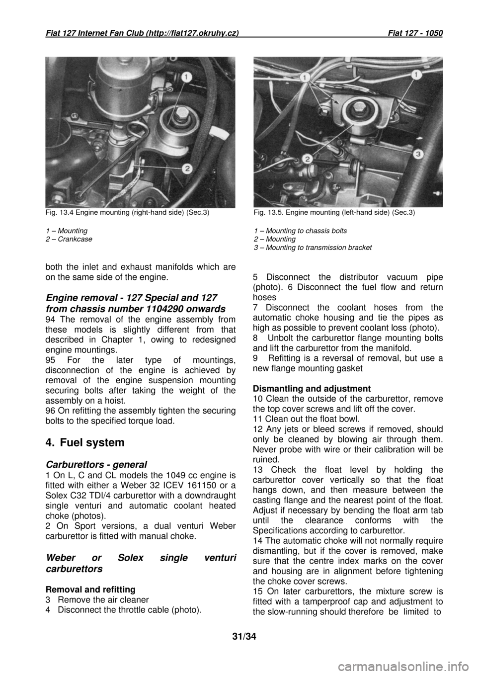
Fig. 13.4 Engine mounting (right-hand side) (Sec.3) Fig. 13.5. Engine mounting (left-hand side) (Sec.3)
1 – Mounting
2 – Crankcase
1 – Mounting to chassis bolts
2 – Mounting
3 – Mounting to transmission bracket
both the inlet and exhaust manifolds which are
on the same side of the engine.
Engine removal - 127 Special and 127
from chassis number 1104290 onwards
94 The removal of the engine assembly from
these models is slightly different from that
described in Chapter 1, owing to redesigned
engine mountings.
95 For the later type of mountings,
disconnection of the engine is achieved by
removal of the engine suspension mounting
securing bolts after taking the weight of the
assembly on a hoist.
96 On refitting the assembly tighten the securing
bolts to the specified torque load.
4. Fuel system
Carburettors - general
1 On L, C and CL models the 1049 cc engine is
fitted with either a Weber 32 ICEV 161150 or a
Solex C32 TDI/4 carburettor with a downdraught
single venturi and automatic coolant heated
choke (photos).
2 On Sport versions, a dual venturi Weber
carburettor is fitted with manual choke.
Weber or Solex single venturi
carburettors
Removal and refitting
3 Remove the air cleaner
4 Disconnect the throttle cable (photo).
5 Disconnect the distributor vacuum pipe
(photo). 6 Disconnect the fuel flow and return
hoses 7 Disconnect the coolant hoses from the
automatic choke housing and tie the pipes as
high as possible to prevent coolant loss (photo).
8 Unbolt the carburettor flange mounting bolts
and lift the carburettor from the manifold.
9 Refitting is a reversal of removal, but use a
new flange mounting gasket
Dismantling and adjustment
10 Clean the outside of the carburettor, remove
the top cover screws and lift off the cover.
11 Clean out the float bowl.
12 Any jets or bleed screws if removed, should
only be cleaned by blowing air through them.
Never probe with wire or their calibration will be
ruined.
13 Check the float level by holding the
carburettor cover vertically so that the float
hangs down, and then measure between the
casting flange and the nearest point of the float.
Adjust if necessary by bending the float arm tab
until the clearance conforms with the
Specifications according to carburettor.
14 The automatic choke will not normally require
dismantling, but if the cover is removed, make
sure that the centre index marks on the cover
and housing are in alignment before tightening
the choke cover screws.
15 On later carburettors, the mixture screw is
fitted with a tamperproof cap and adjustment to
the slow-running should therefore be limited to