engine oil FIAT 500 1957 1.G Owner's Manual
[x] Cancel search | Manufacturer: FIAT, Model Year: 1957, Model line: 500, Model: FIAT 500 1957 1.GPages: 128, PDF Size: 9.01 MB
Page 37 of 128
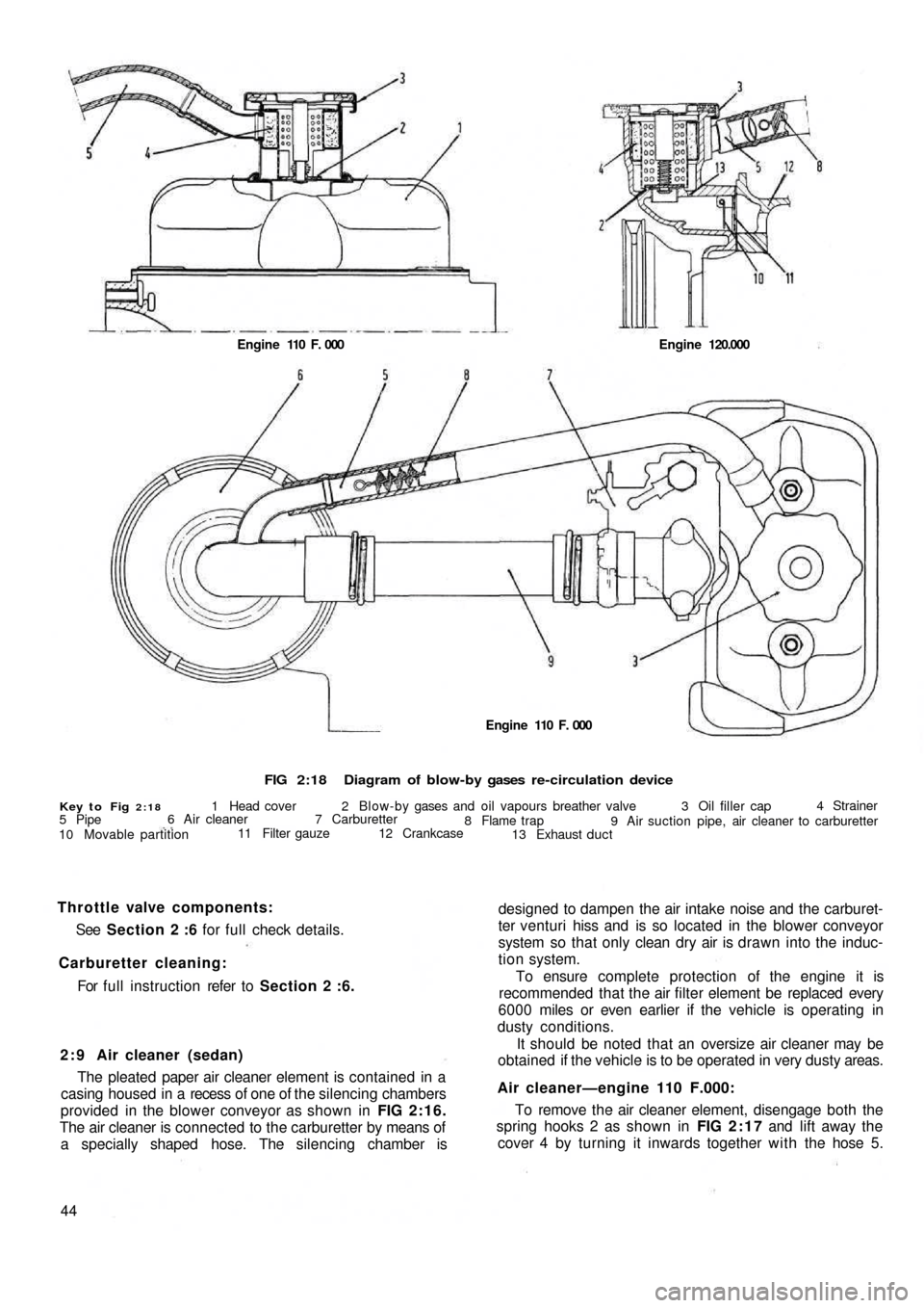
FIG 2:18Diagram of blow-by gases re-circulation device
Key to Fig 2:181 Head cover 2 Blow-by gases and oil vapours breather valve 3 Oil filler cap4 Strainer
9 Air suction pipe, air cleaner to carburetter 8 Flame trap
13 Exhaust duct 12 Crankcase 7 Carburetter 6 Air cleaner
11 Filter gauze
10 Movable partition 5 PipeEngine 110 F. 000 Engine 120.000
designed to dampen the air intake noise and the carburet-
ter venturi hiss and is so located in the blower conveyor
system so that only clean dry air is drawn into the induc-
tion system.
To ensure complete protection of the engine it is
recommended that the air filter element be replaced every
6000 miles or even earlier if the vehicle is operating in
dusty conditions.
It should be noted that an oversize air cleaner may be
obtained if the vehicle is to be operated in very dusty areas.
Air cleaner—engine 110 F.000:
To remove the air cleaner element, disengage both the
spring hooks 2 as shown in FIG 2:17 and lift away the
cover 4 by turning it inwards together with the hose 5. 2 : 9 Air cleaner (sedan)
The pleated paper air cleaner element is contained in a
casing housed in a recess of one of the silencing chambers
provided in the blower conveyor as shown in FIG 2:16.
The air cleaner is connected to the carburetter by means of
a specially shaped hose. The silencing chamber is
44For full instruction refer to Section 2 :6. Carburetter cleaning:See Section 2 :6 for full check details. Throttle valve components:
Engine 110 F. 000
Page 38 of 128
Air cleaner—station wagon:
A pleated paper air cleaner element is housed in a
special air intake chamber connected to the front of the
engine air cooling cowling (see FIG 4 : 2) . This chamber
will be seen located towards the rear of t h e power unit
compartment. Remove the retaining wing nut, lift off the
lid and the element can be withdrawn by lifting upwards.
2:10 Blow-by-gases recirculation device
Engine 110 F.000
All the oil vapours and blow-by-gases that are formed
in the engine crankcase are drawn to the cylinder head
cover recess 1 (see FIG 2:18). From here they travel into
the pipe 5 via a breather valve 2 which is firmly attached to
the oil filler cap 3 and the strainer 4 located in the filler
neck. The oil vapours and gases are then d r a w n back into
the duct 9 from the pipe 5 which connects the air cleaner
6 to the carburetter 7. This ensures a complete closed cir-
cuit circulation.
Engine 120.000:
From engine No. 288156 the oil vapours and blow-by-
gases instead of being exhausted to the atmosphere are
conveyed to the air cleaner and from here they are drawn
back into the combustion chambers. To ensure that an
excessive of oil vapour does not pass along the piping
with the blow-by-gases a diaphragm is fitted in the duct
in front of the breather valve 2 (see FIG 2 :18), the dia-
phragm comprising a filter gauze 11 and moveable parti-
tion 10.
It should be noted that the oil vapour strainer 4 (see
FIG 2:18) and the flame trap 8 can easily be removed
from their seating for cleaning or renewal.
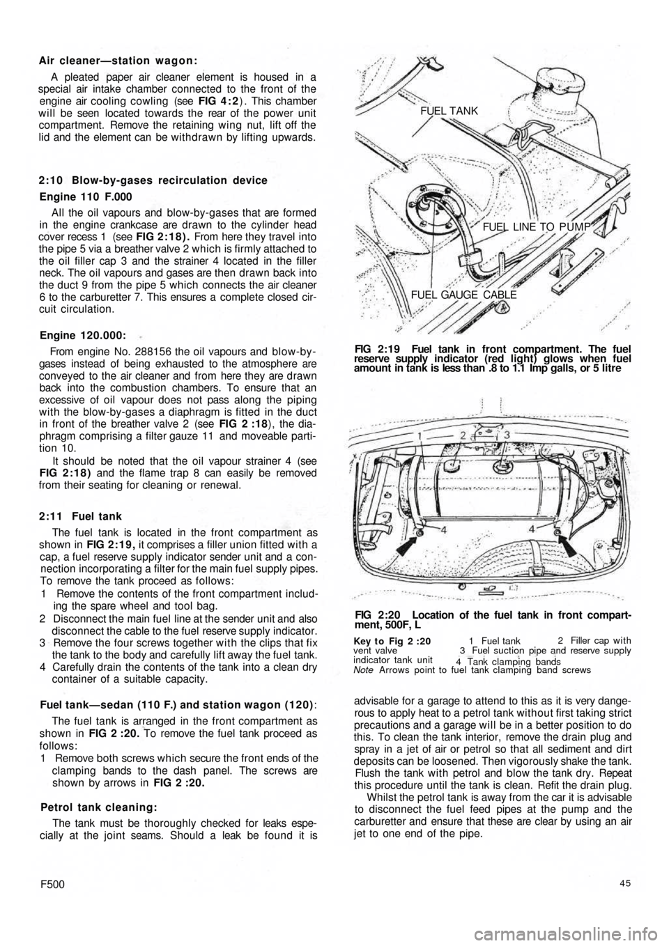
2 : 1 1 Fuel tank
The fuel tank is located in the front compartment as
shown in FIG 2:19, it comprises a filler union fitted with a
cap, a fuel reserve supply indicator sender unit and a con-
nection incorporating a filter for the main fuel supply pipes.
To remove the tank proceed as follows:
1 Remove the contents of the front compartment includ-
ing the spare wheel and tool bag.
2 Disconnect the main fuel line at the sender unit and also
disconnect the cable to the fuel reserve supply indicator.
3 Remove the four screws together w i t h the clips that fix
the tank to the body and carefully lift away the fuel tank.
4 Carefully drain the contents of the tank into a clean dry
container of a suitable capacity.
Fuel tank—sedan (110 F.) and station wagon (120):
The fuel tank is arranged in the front compartment as
shown in FIG 2 :20. To remove the fuel tank proceed as
follows:
1 Remove both screws which secure the front ends of the
clamping bands to the dash panel. The screws are
shown by arrows in FIG 2 :20.
Petrol tank cleaning:
The tank must be thoroughly checked for leaks espe-
cially at the joint seams. Should a leak be found it is
F50045
advisable for a garage to attend to this as it is very dange-
rous to apply heat to a petrol tank without first taking strict
precautions and a garage will be in a better position to do
this. To clean the tank interior, remove the drain plug and
spray in a jet of air or petrol so that all sediment and dirt
deposits can be loosened. Then vigorously shake the tank.
Flush the tank w i t h petrol and blow the tank dry. Repeat
this procedure until the tank is clean. Refit the drain plug.
Whilst the petrol tank is away from the car it is advisable
to disconnect the fuel feed pipes at the pump and the
carburetter and ensure that these are clear by using an air
jet to one end of the pipe.
Key t o Fig 2 :20
Note Arrows point to fuel tank clamping band screws vent valve
indicator tank unit1 Fuel tank2 Filler cap with
3 Fuel suction pipe and reserve supply
4 Tank clamping bands
FIG 2:20 Location of the fuel tank in front compart-
ment, 500F, L FIG 2:19 Fuel tank in front compartment. The fuel
reserve supply indicator (red light) glows when fuel
amount in tank is less than .8 to 1.1 Imp galls, or 5 litre FUEL TANK
FUEL LINE TO PUMP
FUEL GAUGE CABLE
Page 41 of 128
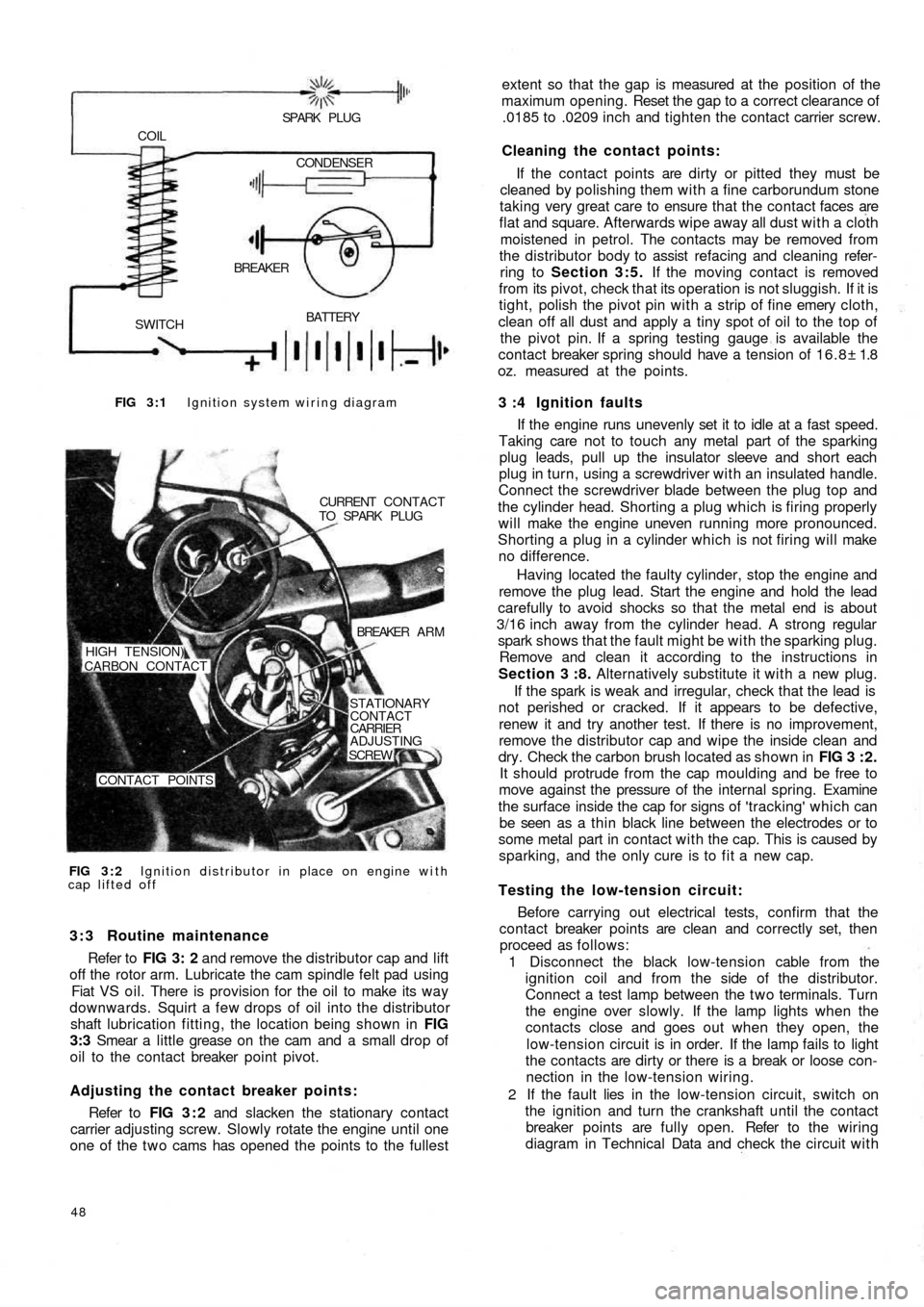
FIG 3 : 1 Ignition system wiring diagram
BATTERY
SWITCHBREAKER COIL
SPARK PLUG
CONDENSER
FIG 3 : 2 Ignition distributor in place on engine with
cap lifted offCURRENT CONTACT
TO SPARK PLUG
BREAKER A R M
STATIONARY
CONTACT
CARRIER
ADJUSTING
SCREW
CONTACT POINTS HIGH TENSION)
CARBON CONTACT
3 : 3 Routine maintenance
Refer to FIG 3: 2 and remove the distributor cap and lift
off the rotor arm. Lubricate the cam spindle felt pad using
Fiat VS oil. There is provision for the oil to make its way
downwards. Squirt a few drops of oil into the distributor
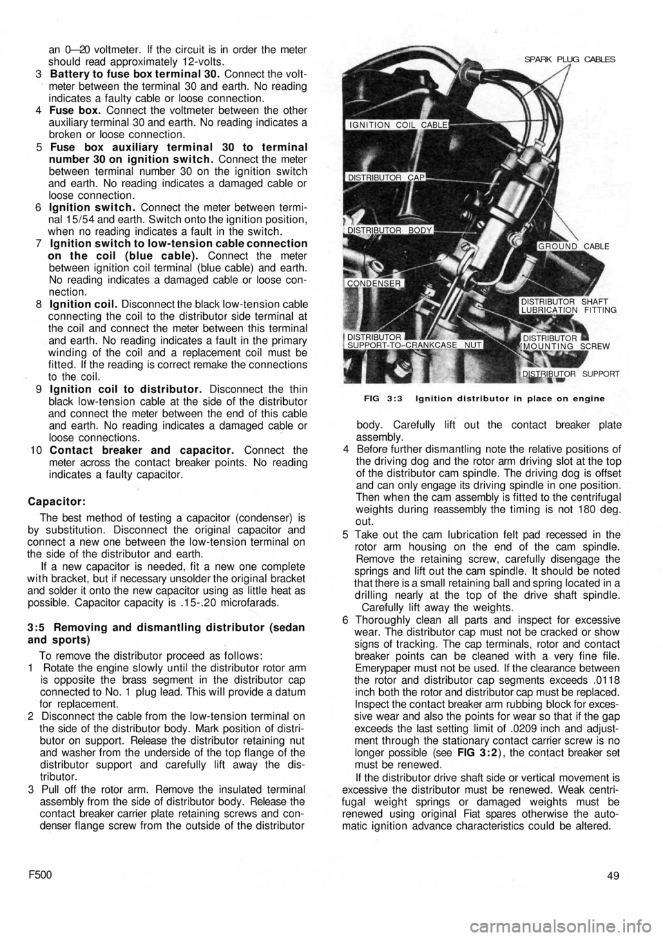
shaft lubrication fitting, the location being shown in FIG
3:3 Smear a little grease on the cam and a small drop of
oil to the contact breaker point pivot.
Adjusting the contact breaker points:
Refer to FIG 3 : 2 and slacken the stationary contact
carrier adjusting screw. Slowly rotate the engine until one
one of the t w o cams has opened the points to the fullest
48
extent so that the gap is measured at the position of the
maximum opening. Reset the gap to a correct clearance of
.0185 to .0209 inch and tighten the contact carrier screw.
Cleaning the contact points:
If the contact points are dirty or pitted they must be
cleaned by polishing them with a fine carborundum stone
taking very great care to ensure that the contact faces are
flat and square. Afterwards wipe away all dust with a cloth
moistened in petrol. The contacts may be removed from
the distributor body to assist refacing and cleaning refer-
ring to Section 3:5. If the moving contact is removed
from its pivot, check that its operation is not sluggish. If it is
tight, polish the pivot pin with a strip of fine emery cloth,
clean off all dust and apply a tiny spot of oil to the top of
the pivot pin. If a spring testing gauge is available the
contact breaker spring should have a tension of 16.8± 1.8
oz. measured at the points.
3 :4 Ignition faults
If the engine runs unevenly set it to idle at a fast speed.
Taking care not to touch any metal part of the sparking
plug leads, pull up the insulator sleeve and short each
plug in turn, using a screwdriver with an insulated handle.
Connect the screwdriver blade between the plug top and
the cylinder head. Shorting a plug which is firing properly
will make the engine uneven running more pronounced.
Shorting a plug in a cylinder which is not firing will make
no difference.
Having located the
faulty cylinder, stop the engine and
remove the plug lead. Start the engine and hold the lead
carefully to avoid shocks so that the metal end is about
3/16 inch away from the cylinder head. A strong regular
spark shows that the fault might be with the sparking plug.
Remove and clean it according to the instructions in
Section 3 :8. Alternatively substitute it with a new plug.
If the spark is weak and irregular, check that the lead is
not perished or cracked. If it appears to be defective,
renew it and try another test. If there is no improvement,
remove the distributor cap and wipe the inside clean and
dry. Check the carbon brush located as shown in FIG 3 : 2 .
It should protrude from the cap moulding and be free to
move against the pressure of the internal spring. Examine
the surface inside the cap for signs of 'tracking' which can
be seen as a thin black line between the electrodes or to
some metal part in contact with the cap. This is caused by
sparking, and the only cure is to fit a new cap.
Testing the low-tension circuit:
Before carrying out electrical tests, confirm that the
contact breaker points are clean and correctly set, then
proceed as follows:
1 Disconnect the black low-tension cable from the
ignition coil and from the side of the distributor.
Connect a test lamp between the t w o terminals. Turn
the engine over slowly. If the lamp lights when the
contacts close and goes out when they open, the
low-tension circuit is in order. If the lamp fails to light
the contacts are dirty or there is a break or loose con-
nection in the low-tension wiring.
2 If the fault lies in the
low-tension circuit, switch on
the ignition and turn the crankshaft until the contact
breaker points are fully open. Refer to the wiring
diagram in Technical Data and check the circuit with
Page 42 of 128
a n 0—20 v o ltmeter. If the circuit is in order the meter
should read approximately 12-volts.
3 Battery to fuse box terminal 30. Connect the volt-
meter between the terminal 30 and earth. No reading
indicates a faulty cable or loose connection.
4 Fuse box. Connect the voltmeter between the other
auxiliary terminal 30 and earth. No reading indicates a
broken or loose connection.
5 Fuse box auxiliary terminal 30 to terminal
number 30 on ignition switch. Connect the meter
between terminal number 30 on the ignition switch
and earth. No reading indicates a damaged cable or
loose connection.
6 Ignition switch. Connect the meter between termi-
nal 15/54 and earth. Switch onto the ignition position,
when no reading indicates a fault in the switch.
7 Ignition switch to low-tension cable connection
on the coil (blue cable). Connect the meter
between ignition coil terminal (blue cable) and earth.
No reading indicates a damaged cable or loose con-
nection.
8 Ignition coil. Disconnect the black low-tension cable
connecting the coil to the distributor side terminal at
the coil and connect the meter between this terminal
and earth. No reading indicates a fault in the primary
winding of the coil and a replacement coil must be
fitted. If the reading is correct remake the connections
to the coil.
9 Ignition coil to distributor. Disconnect the thin
black low-tension cable at the side of the distributor
and connect the meter between the end of this cable
and earth. No reading indicates a damaged cable or
loose connections.
10 Contact breaker and capacitor. Connect the
meter across the contact breaker points. No reading
indicates a faulty capacitor.
Capacitor:
The best method of testing a capacitor (condenser) is
by substitution. Disconnect the original capacitor and
connect a new one between the low-tension terminal on
the side of the distributor and earth.
If a new capacitor is needed, fit a new one complete
w i t h bracket, but if necessary unsolder the original bracket
and solder it onto the new capacitor using as little heat as
possible. Capacitor capacity is .15-.20 microfarads.
3 : 5 Removing and dismantling distributor (sedan
and sports)
To remove the distributor proceed as follows:
1 Rotate the engine slowly until the distributor rotor arm
is opposite the brass segment in the distributor cap
connected to No. 1 plug lead. This will provide a datum
for replacement.
2 Disconnect the cable from the low-tension terminal on
the side of the distributor body. Mark position of distri-
butor on support. Release the distributor retaining nut
and washer from the underside of the top flange of the
distributor support and carefully lift away the dis-
tributor.
3 Pull off the rotor arm. Remove the insulated terminal
assembly from the side of distributor body. Release the
contact breaker carrier plate retaining screws and con-
denser flange screw from the outside of the distributor
F50049 body. Carefully lift out the contact breaker plate
assembly.
4 Before further dismantling note the relative positions of
the driving dog and the rotor arm driving slot at the top
of the distributor cam spindle. The driving dog is offset
and can only engage its driving spindle in one position.
Then when the cam assembly is fitted to the centrifugal
weights during reassembly the timing is not 180 deg.
out.
5 Take out the cam lubrication felt pad recessed in the
rotor arm housing on the end of the cam spindle.
Remove the retaining screw, carefully disengage the
springs and lift out the cam spindle. It should be noted
that there is a small retaining ball and spring located in a
drilling nearly at the top of the drive shaft spindle.
Carefully lift away the weights.
6 Thoroughly clean all parts and inspect for excessive
wear. The distributor cap must not be cracked or show
signs of tracking. The cap terminals, rotor and contact
breaker points can be cleaned with a very fine file.
Emerypaper must not be used. If the clearance between
the rotor and distributor cap segments exceeds .0118
inch both the rotor and distributor cap must be replaced.
Inspect the contact breaker arm rubbing block for exces-
sive wear and also the points for wear so that if the gap
exceeds the last setting limit of .0209 inch and adjust-
ment through the stationary contact carrier screw is no
longer possible (see FIG 3 : 2) , the contact breaker set
must be renewed.
If the distributor drive shaft side or vertical movement is
excessive the distributor must be renewed.
Weak centri-
fugal weight springs or damaged weights must be
renewed using original Fiat spares otherwise the auto-
matic ignition advance characteristics could be altered.
FIG 3 : 3 Ignition distributor in place on engine SPARK PLUG CABLES
IGNITION COIL CABLE!
DISTRIBUTOR CAP
DISTRIBUTOR BODY
GROUND CABLE
CONDENSER
DISTRIBUTOR SHAFT
LUBRICATION FITTING
DISTRIBUTORSUPPORT-TO--CRANKCASE NUT
[MOUNTING SCREWDISTRIBUTOR
DISTRIBUTOR SUPPORT
Page 43 of 128
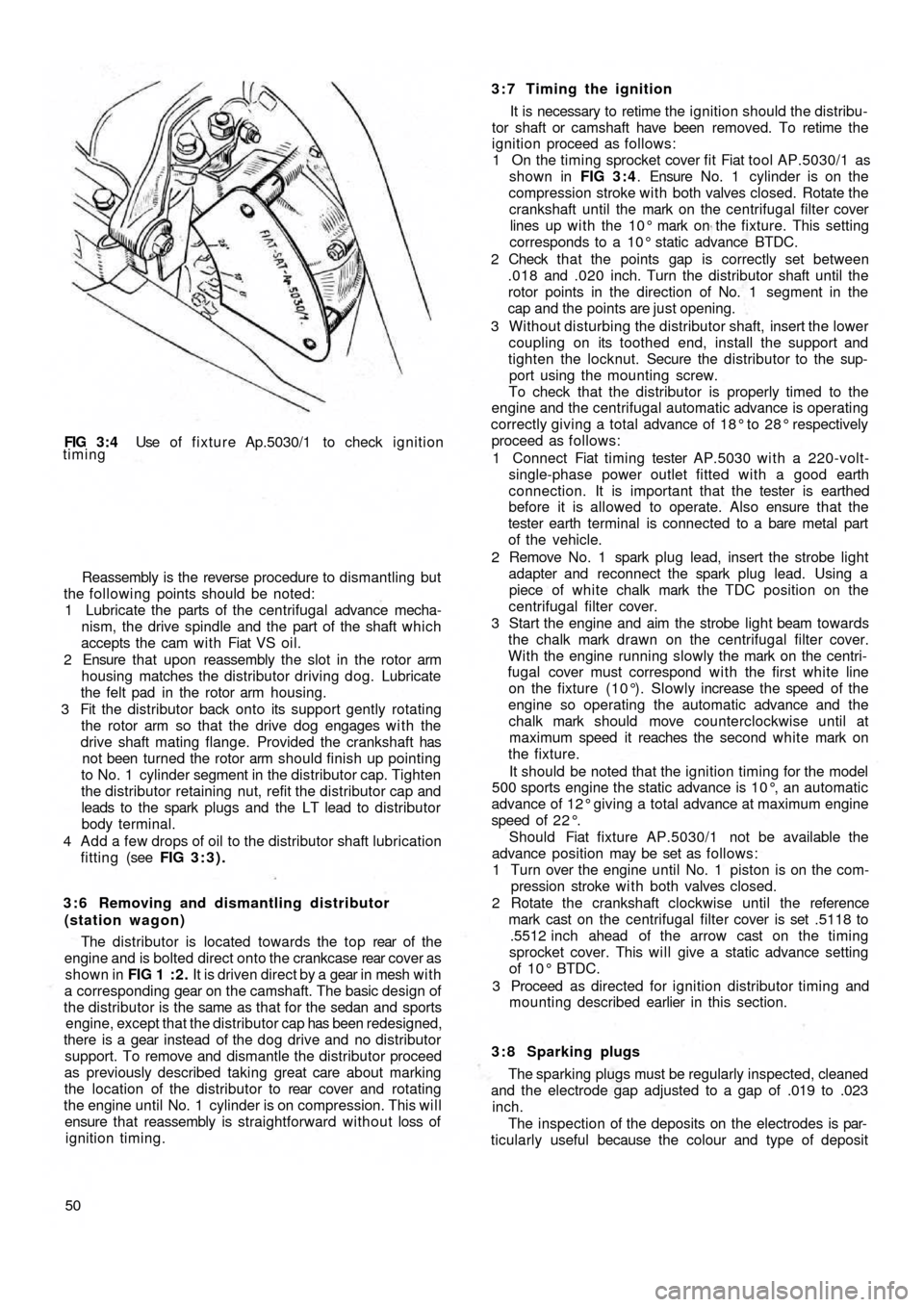
FIG 3 : 4 Use of fixture Ap.5030/1 to check ignition
timing
Reassembly is the reverse procedure to dismantling but
the following points should be noted:
1 Lubricate the parts of the centrifugal advance mecha-
nism, the drive spindle and the part of the shaft which
accepts the cam w i t h Fiat VS oil.
2 Ensure that upon reassembly the slot in the rotor arm
housing matches the distributor driving dog. Lubricate
the felt pad in the rotor arm housing.
3 Fit the distributor back onto its support gently rotating
the rotor arm so that the drive dog engages w i t h the
drive shaft mating flange. Provided the crankshaft has
not been turned the rotor arm should finish up pointing
to No. 1 cylinder segment in the distributor cap. Tighten
the distributor retaining nut, refit the distributor cap and
leads to the spark plugs and the LT lead to distributor
body terminal.
4 Add a few drops of oil to the distributor shaft lubrication
fitting (see FIG 3:3).
3 : 6 Removing and dismantling distributor
(station wagon)
The distributor is located towards the top rear of t h e
engine and is bolted direct onto the crankcase rear cover as
shown in FIG 1 : 2 . It is driven direct by a gear in mesh w i t h
a corresponding gear on the camshaft. The basic design of
the distributor is the same as that for the sedan and sports
engine, except that the distributor cap has been redesigned,
there is a gear instead of the dog
drive and no distributor
support. To remove and dismantle the distributor proceed
as previously described taking great care about marking
the location of the distributor to rear cover and rotating
the engine until No. 1 cylinder is on compression. This will
ensure that reassembly is straightforward without loss of
ignition timing.
503:7 Timing the ignition
It is necessary to retime the ignition should the distribu-
tor shaft or camshaft have been removed. To retime the
ignition proceed as follows:
1 On the timing sprocket cover fit Fiat tool AP.5030/1 as
shown in FIG 3 : 4. Ensure No. 1 cylinder is on the
compression stroke with both valves closed. Rotate the
crankshaft until the mark on the centrifugal filter cover
lines up w i t h the 10° mark on the fixture. This setting
corresponds to a 10° static advance BTDC.
2 Check t h a t the points gap is correctly set between
.018 and .020 inch. Turn the distributor shaft until the
rotor points in the direction of No. 1 segment in the
cap and the points are just opening.
3 Without disturbing the distributor shaft, insert the lower
coupling on its toothed end, install the support and
tighten the locknut. Secure the distributor to the sup-
port using the mounting screw.
To check that the distributor is properly timed to the
engine and the centrifugal automatic advance is operating
correctly giving a
total advance of 18° to 28° respectively
proceed as follows:
1 Connect Fiat timing tester AP.5030 with a 220-volt-
single-phase power outlet fitted with a good earth
connection. It is important that the tester is earthed
before it is allowed to operate. Also ensure that the
tester earth terminal is connected to a bare metal part
of the vehicle.
2 Remove No. 1 spark plug lead, insert the strobe light
adapter and reconnect the spark plug lead. Using a
piece of white chalk mark the TDC position on the
centrifugal filter cover.
3 Start the engine and aim the strobe light beam towards
the chalk mark drawn on the centrifugal filter cover.
With the engine running slowly the mark on the centri-
fugal cover must correspond wi th the first white line
on the fixture (10°). Slowly increase the speed of the
engine so operating the automatic advance and the
chalk mark should move counterclockwise until at
maximum speed it reaches the second white mark on
the fixture.
It should be noted that the ignition timing for the model
500 sports engine the static advance is 10°, an automatic
advance of 12° giving a total advance at maximum engine
speed of 2 2 ° .
Should Fiat fixture AP.5030/1 not be available the
advance position may be set as follows:
1 Turn over the
engine until No. 1 piston is on the com-
pression stroke w i t h both valves closed.
2 Rotate the crankshaft clockwise until the reference
mark cast on the centrifugal filter cover is set .5118 to
.5512 inch ahead of the arrow cast on the timing
sprocket cover. This will give a static advance setting
of 10° BTDC.
3 Proceed as directed for ignition distributor timing and
mounting described earlier in this section.
3 : 8 Sparking plugs
The sparking plugs must be regularly inspected, cleaned
and the electrode gap adjusted to a gap of .019 to .023
inch.
The inspection of the deposits on the electrodes is par-
ticularly useful because the colour and type of deposit
Page 44 of 128
indicates the condition inside the combustion chamber
and may be used as a guide to engine tuning.
Before the spark plugs are removed b l o w away any
loose dirt from the plug recesses using a compressed air
jet or tyre pump. Store the plugs in the order of removal
ready for inspection.
Examine the gaskets and if they are about half their
thickness they may be used again otherwise they must be
replaced.
Inspect the electrode end of the plugs and note the
type and colour of the deposit. Normally it should be
powdery and range from b r o w n to a greyish tan in colour.
There will also be slight wear of the electrodes and the
general effect described is one which comes from mixed
periods of high-speed and low-speed driving. Cleaning
and resetting the gap is all that will be necessary.
If the deposits are white or yellowish they indicate long
periods of constant-speed driving or much low-speed
city driving. Again, the treatment is straightforward.
Dry, black, fluffy deposits are usually the result of
running with too rich a mixture. Incomplete combustion
of the petrol air charge may also be a cause and this might
be traced to a defect in the ignition system or excessive
idling.
Overheated sparking plugs have a white blistered look
about the centre electrode and the side electrode may be
badly eroded. This may be caused by poor cooling, wrong
ignition timing or sustained high speeds under heavy load.
To clean the sparking plugs effectively they should be
cleaned using an abrasive blasting machine and tested
under pressure once the electrodes have been reset. File
these until they are clean, bright and the faces parallel and
set the gap to .019 to .023 inch. Do not try to bend the
centre electrode.
Before replacing the plugs use a wire brush to clean the
threads taking care that the electrodes are not touched.
Thoroughly clean the spark plug in petrol, and dry using a
compressed air jet or a tyre pump. If difficulty is found in
screwing the plugs into the cylinder head by hand run a
tap d o w n the threads to clear away any carbon. If a tap is
not available use an old sparking plug with crosscuts d o w nthe threads. Finally tighten the plugs to a torque wrench
setting of 18 to 21 Ib ft.
Sparking plug leads:
The spark plug leads and the lead from the coil to the
distributor cap must be regularly checked for cracking of
the insulation and also correct seating in the distributor
cap and coil top. It is recommended that silicone grease is
smeared around the sockets before the leads are replaced
to ensure no moisture may enter causing difficult starting.
3 : 9 The distributor driving spindle (sedan and
sports engine)
If for any reason, the driving spindle has been removed
from its housing in the crankcase, it must be correctly
meshed w i t h the camshaft gear otherwise it
will be impos-
sible to set the ignition timing.
3:10 Fault diagnosis
(a) Engine w i l l not fire
1 Battery discharged
2 Distributor contact points dirty, pitted or maladjusted
3 Distributor cap dirty, cracked or tracking
4 Carbon brush inside distributor cap not touching rotor
5 Faulty cable or loose connection in low-tension circuit
6 Distributor rotor arm cracked
7 Faulty coil
8 Broken contact breaker spring
9 Contact points stuck open
(b) Engine misfires
1 Check 2, 3, 4, and 7 in (a)
2 Weak contact breaker spring
3 High-tension plug and coil leads cracked or perished
4 Sparking plug(s) loose
5 Sparking plug insulation cracked
6 Sparking plug gap incorrectly set
7 Ignition timing too far advanced
Page 47 of 128
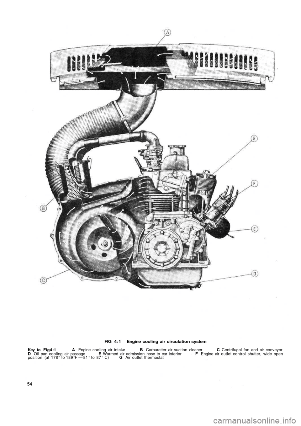
FIG 4 : 1 Engine cooling air circulation system
Key to Fig4:1 A Engine cooling air intake B Carburetter air suction cleaner C Centrifugal fan and air conveyor
D Oil pan cooling air passage E Warmed air admission hose to car interior F Engine air outlet control shutter, wide open
position (at 178° to 189°F — 81° to 87° C) G Air outlet thermostat
54
Page 49 of 128
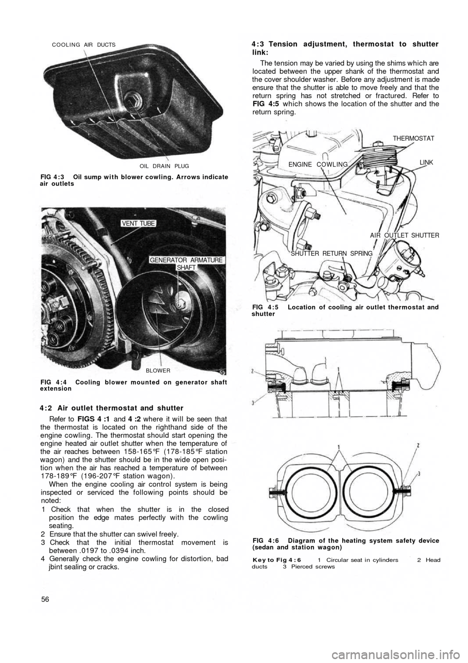
OIL DRAIN PLUG COOLING AIR DUCTS
FIG 4 : 3 Oil sump with blower cowling. Arrows indicate
air outlets
BLOWER
SHAFT GENERATOR ARMATURE
VENT TUBE
FIG 4 : 4 Cooling blower mounted on generator shaft
extension
4 : 2 Air outlet thermostat and shutter
Refer to FIGS 4 :1 and 4 :2 where it will be seen that
the thermostat is located on the righthand side of the
engine cowling. The thermostat should start opening the
engine heated air outlet shutter when the temperature of
the air reaches between 158-165°F (178-185°F station
wagon) and the shutter should be in the wide open posi-
tion when the air has reached a temperature of between
178-189°F (196-207°F station wagon).
When the engine cooling air control system is being
inspected or serviced the following points should be
noted:
1 Check that when the shutter is in the closed
position the edge mates perfectly with the cowling
seating.
2 Ensure that the shutter can swivel freely.
3 Check that the initial thermostat movement is
between .0197 to .0394 inch.
4 Generally check the engine cowling for distortion, bad
jbint sealing or cracks.
56
Key to Fig 4 : 6 1 Circular seat i n cylinders 2 Head
ducts 3 Pierced screws
FIG 4 : 6 Diagram of the heating system safety device
(sedan and station wagon) FIG 4 : 5 Location of cooling air outlet thermostat and
shutter
ENGINE COWLING.
THERMOSTAT
LINK
AIR OUTLET SHUTTER
SHUTTER RETURN SPRING
4 : 3 Tension adjustment, thermostat to shutter
link:
The tension may be varied by using the shims which are
located between the upper shank of the thermostat and
the cover shoulder washer. Before any adjustment is made
ensure that the shutter is able to move freely and that the
return spring has not stretched or fractured. Refer to
FIG 4:5 which shows the location of the shutter and the
return spring.
Page 57 of 128
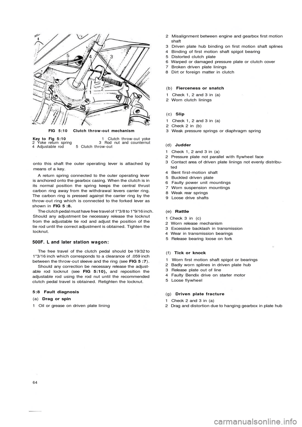
FIG 5:10 Clutch throw-out mechanism
Key to Fig 5:10 1 Clutch throw-out yoke
2 Yoke return spring 3 Rod nut and counternut
4 Adjustable rod 5 Clutch throw-out
onto this shaft the outer operating lever is attached by
means of a key.
A return spring connected to the outer operating lever
is anchored onto the gearbox casing. When the clutch is in
its normal position the spring keeps the central thrust
carbon ring away from the withdrawal levers carrier ring.
The carbon ring is pressed against the carrier ring by the
throw-out ring which is connected to the forked lever as
shown in FIG 5 : 8 .
The clutch pedal must have free travel of 1"3/8 to 1"9/16 inch.
Should any adjustment be necessary release the locknut
from the adjustable tie rod and adjust the position of the
tie rod until the correct adjustment is obtained. Tighten the
locknut.
500F. L and later station wagon:
The free travel of the clutch pedal should be 19/32 to
1"3/16 inch which corresponds to a clearance of .059 inch
between the throw-out sleeve and the ring (see FIG 5 : 7).
Should any correction be necessary release the adjust-
able rod locknut (see FIG 5:10), and reposition the
adjustable rod using the rod nut until the recommended
clutch pedal travel is obtained. Retighten the locknut.
5 : 8 Fault diagnosis
(a) Drag or spin
1 Oil or grease on driven plate lining
64
(g) Driven plate fracture
1 Check 2 and 3 in (a)
2 Drag and distortion due to hanging gearbox in plate hub (f) Tick or knock
1 Worn first motion shaft spigot or bearings
2 Badly worn splines in driven plate hub
3 Release plate out of line
4 Faulty Bendix drive on starter motor
5 Loose flywheel
(e) Rattle
1 Check 3 in (c)
2 Worn release mechanism
3 Excessive backlash in transmission
4 Wear in transmission bearings
5 Release bearing loose on fork (d) Judder
1 Check 1, 2 and 3 in (a)
2 Pressure plate not parallel with flywheel face
3 Contact area of driven plate linings not evenly distribu-
ted
4 Bent first-motion shaft
5 Buckled driven plate
6 Faulty power unit mountings
7 Worn suspension mountings
8 Weak rear springs
9 Loose drive shafts (c) Slip
1 Check 1, 2 and 3 in (a)
2 Check 2 in (b)
3 Weak pressure springs or diaphragm spring (b) Fierceness or snatch
1 Check 1, 2 and 3 in (a)
2 Worn clutch linings 2 Misalignment between engine and gearbox first motion
shaft
3 Driven plate hub binding on first motion shaft splines
4 Binding of first motion shaft spigot bearing
5 Distorted clutch plate
6 Warped or damaged pressure plate or clutch cover
7 Broken driven plate linings
8 Dirt or foreign matter in clutch
Page 59 of 128
PRIMARY SHAFT-TO-CLUTCH
SHAFT MOUNTING PINCLUTCH SHAFT SEAL PRIMARY SHAFT WITH
1st, 3 r d A N D 4 t h SPEED
GEAR CLUSTER
2 n d SPEED
DRIVE GEARPRIMARY SHAFT
FRONT BALL BEARINGPRIMARY SHAFT
REAR BALL BEARING
PRIMARY
SHAFT-TO-CLUTCH
i SHAFT JOINING SLEEVEJOINING SLEEVELOCKRING
SPEED SELECTOR LEVER
CLUTCH SHAFT
LAYSHAFT WITH BEVEL PINION
SPEEDOMETER DRIVE GEAR
2 n d SPEED ENGAGEMENT
SLIDING SLEEVE
2 N D SPEED DRIVEN GEAR
LAYSHAFT FRONT BALL
BEARING
3 r d SPEED DRIVEN GEARHUB FOR
SLEEVE
3rd AND 4th/
SPEED ENGAGEMENT
SLIDING SLEEVE4 t h SPEED
DRIVEN GEARLAYSHAFT REAR ROLLER BEARING
LAYSHAFT-TO-PINION
ADJUSTMENT WASHER 1st SPEED AND)
REVERSE SLIDING GEAR
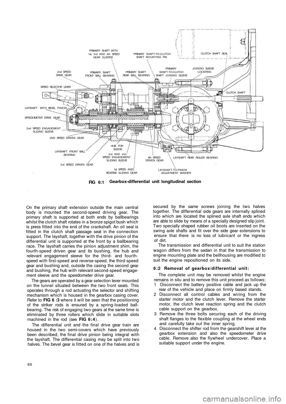
FIG 6:1Gearbox-differential unit longitudinal section
On the primary shaft extension outside the main central
body is mounted the second-speed driving gear. The
primary shaft is supported at both ends by ballbearings
whilst the clutch shaft rotates in a bronze spigot bush which
is press fitted into the end of the crankshaft. An oil seal is
fitted in the clutch shaft passage seat in the c o n n e c t i o n
support. The layshaft, together with the drive pinion of the
differential unit is supported at the front by a ballbearing
race. The layshaft carries the pinion adjustment shim, the
fourth-speed driven gear and its bushing, the hub and
relevant engagement sleeve for the t h i r d - and fourth-
speed w i t h first-speed and reverse-speed, the third-speed
gear and bushing and, outside the casing the second gear
and bushing, the hub with relevant second-speed engage-
ment sleeve and the speedometer drive gear.
The gears are operated by a gear selection lever mounted
on the tunnel situated between the two front seats. This
operates through a rod actuating the selector and shifting
mechanism which is housed in the gearbox casing cover.
Refer to FIG 6 :3 where it will be seen th a t the positioning
of the striker rods is ensured by a spring-loaded ball-
bearing. The risk of engaging two gears at the same time is
eliminated by three rollers which slide in suitable slots
machined in the rod (see FIG 6 : 4).
The differential unit and the final drive gear train are
housed in the t w o semi-covers which
have previously
been described, the final drive pinion being integral with
the layshaft. The differential casing may be split into t w o
halves. The bevel gear is fitted on one of the halves and is
66
secured by the same screws joining the two halves
together. The differential side gears are internally splined
into which are located the splined axle shaft ends which
are able to slide by means of a specially designed slip joint.
Two specially shaped rubber oil boots are inserted on the
swing axle shafts and fit over the side gear extensions to
ensure that there is no loss of lubricant or the ingress
of dirt.
The transmission and differential unit to suit the station
wagon differs from the sedan in that the transmission to
engine mounting plate and the bellhousing are modified to
suit the engine repositioned on its side.
6 : 2 Removal of gearbox/differential unit:
The complete unit may be removed whilst the engine
remains in situ and to remove this unit proceed as follows:
1 Disconnect the battery positive cable and jack up the
rear of t h e vehicle and place on firmly based stands.
2 Disconnect all control cables and wiring from the
starter motor and the clutch lever. Remove the starter
motor, the clutch lever reaction spring and the clutch
cable support on the gearbox.
3 Remove the three bolts securing each of the driving
shaft flanges to the flexible coupling at the wheel ends
and carefully take out the inner spring.
4 Disconnect the shifter rod from the gearshift lever at the
gearbox extension and also the
speedometer drive
cable. Remove also the flywheel undercover. Place a
suitable support under the engine.