fuel filter FIAT 500 1957 1.G Workshop Manual
[x] Cancel search | Manufacturer: FIAT, Model Year: 1957, Model line: 500, Model: FIAT 500 1957 1.GPages: 128, PDF Size: 9.01 MB
Page 3 of 128
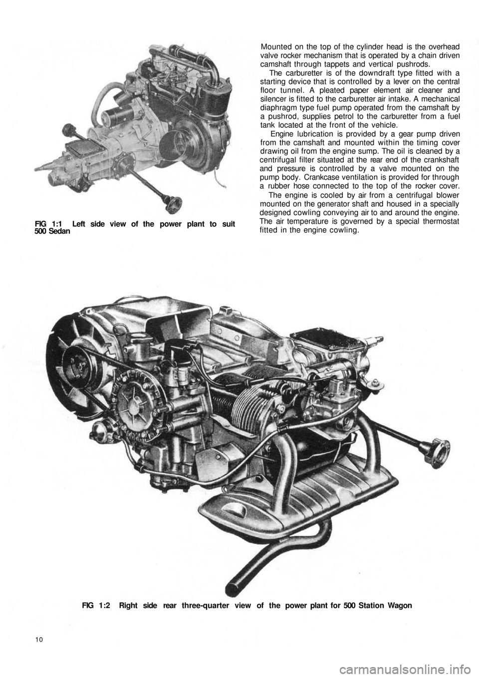
FIG 1:1 Left side view of the power plant to suit
500 Sedan
10
FIG 1:2 Right side rear three-quarter view of the power plant for 500 Station Wagon Mounted on the top of the cylinder head is the overhead
valve rocker mechanism that is operated by a chain driven
camshaft through tappets and vertical pushrods.
The carburetter is of the downdraft type fitted with a
starting device that is controlled by a lever on the central
floor tunnel. A pleated paper element air cleaner and
silencer is fitted to the carburetter air intake. A mechanical
diaphragm type fuel pump operated from the camshaft by
a pushrod, supplies petrol to the carburetter from a fuel
tank located at the front of the vehicle.
Engine lubrication is provided by a gear pump driven
from the camshaft and mounted within the timing cover
drawing oil from the engine sump. The oil is cleaned by a
centrifugal filter situated at the rear end of t h e crankshaft
and pressure is controlled by a valve mounted on the
pump body. Crankcase ventilation is provided for through
a rubber hose connected to the top of the rocker cover.
The engine is cooled by air from a centrifugal blower
mounted on the generator shaft and housed in a specially
designed cowling conveying air to and around the engine.
The air temperature is governed by a special thermostat
fitted in the engine cowling.
Page 8 of 128
6 Release the ignition distributor support retaining nut
and lift away the distributor together w i t h its support.
7 Remove all the mounting bolts of the engine cooling
cowling and lift away the assembly. Release the t w o
carburetter retaining nuts and carefully remove the
carburetter together with its drip tray.
8 Lift away the valve rocker assembly having first
released the t w o retaining nuts together with the plain
washers and lock washers. Carefully lift out the valve
rocker pushrods noting their relevant positions.
9 Slacken the four central cylinder head cap nuts and
the four conventional nuts in the order, shown in
FIG 1 :44 or 1 :46. Lift the cylinder head from the
barrels. If difficulty is experienced it is essential to use
Fiat tool A.40014 or a similar drilled plate, otherwise
serious damage could be caused if other means are
used (see FIG 1:9).
10 Remove the four pushrod sleeves and the casing
containing the oil ducting to the overhead valve gear.
11 Remove the fuel pump retaining nuts and washers
and lift away the pump. Carefully pull out the pump
control pushrod from the crankcase.
12 Remove the six screws holding the centrifugal oil filter
pulley cover and lift away the cover. Remove the
centrifugal filter mounting flange by unscrewing the
crankshaft central bolt. Also remove the timing cover
containing the oil pump gears and the oil pressure
regulating valve. Note the position of the nuts,
toothed and plain
washers for correct reassembly.
13 Release t h e four camshaft sprocket retaining bolts and
lift away the sprocket and timing chain. Using Fiat
pulley A.46020 or a large universal two-leg puller as
shown in FIG 1 :10 remove the crankshaft sprocket
and its body.
14 Carefully lift out the rocker pushrod tappets making a
note of their location and gently pull out the camshaft
making sure the front bearing bore is not damaged by
the cam lobes or distributor drive gear.
15 Mark the flywheel and crankshaft to ensure correct
reassembly and release the six f l y w h e e l retaining bolts
together w i t h the lockwashers and lift away the fly-
wheel.
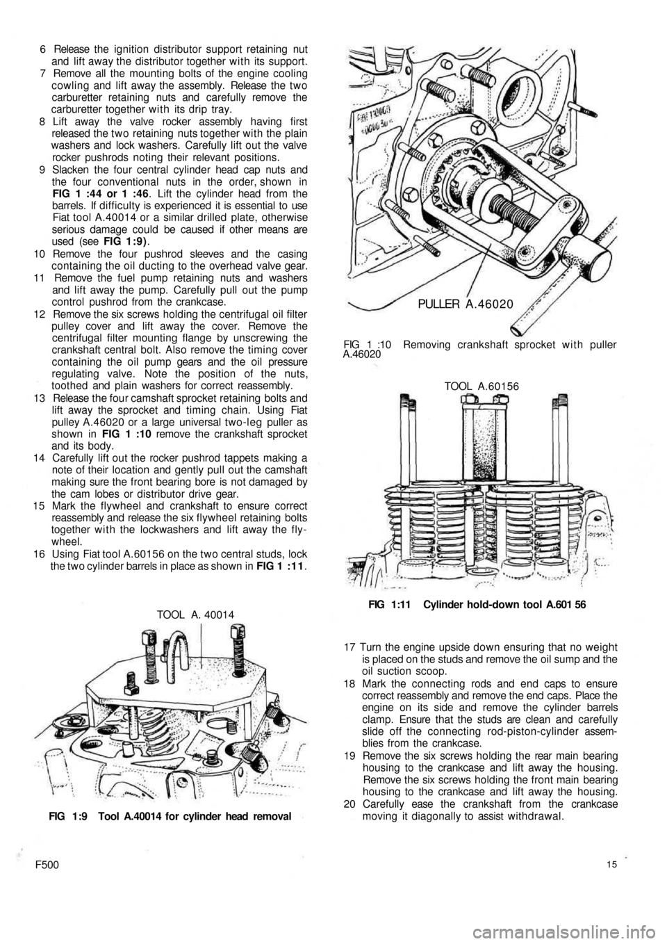
16 Using Fiat tool A.60156 on the two central studs, lock
the two cylinder barrels in place as shown in FIG 1 : 1 1.
TOOL A. 40014
FIG 1:9 Tool A.40014 for cylinder head removal
F50015
17 Turn the engine upside down ensuring that no weight
is placed on the studs and remove the oil sump and the
oil suction scoop.
18 Mark the connecting rods and end caps to ensure
correct reassembly and remove the end caps. Place the
engine on its side and remove the cylinder barrels
clamp. Ensure that the studs are clean and carefully
slide off the connecting rod-piston-cylinder assem-
blies from the crankcase.
19 Remove the six screws holding the rear main bearing
housing to the crankcase and lift away the housing.
Remove the six screws holding the front main bearing
housing to the crankcase and lift away the housing.
20 Carefully ease the crankshaft from the crankcase
moving it diagonally to assist withdrawal. FIG 1:11 Cylinder hold-down tool A.601 56 TOOL A.60156 FIG 1 :10 Removing crankshaft sprocket w i t h puller
A.46020
PULLER A.46020
Page 9 of 128
STUD REMOVAL
PULLER 40010
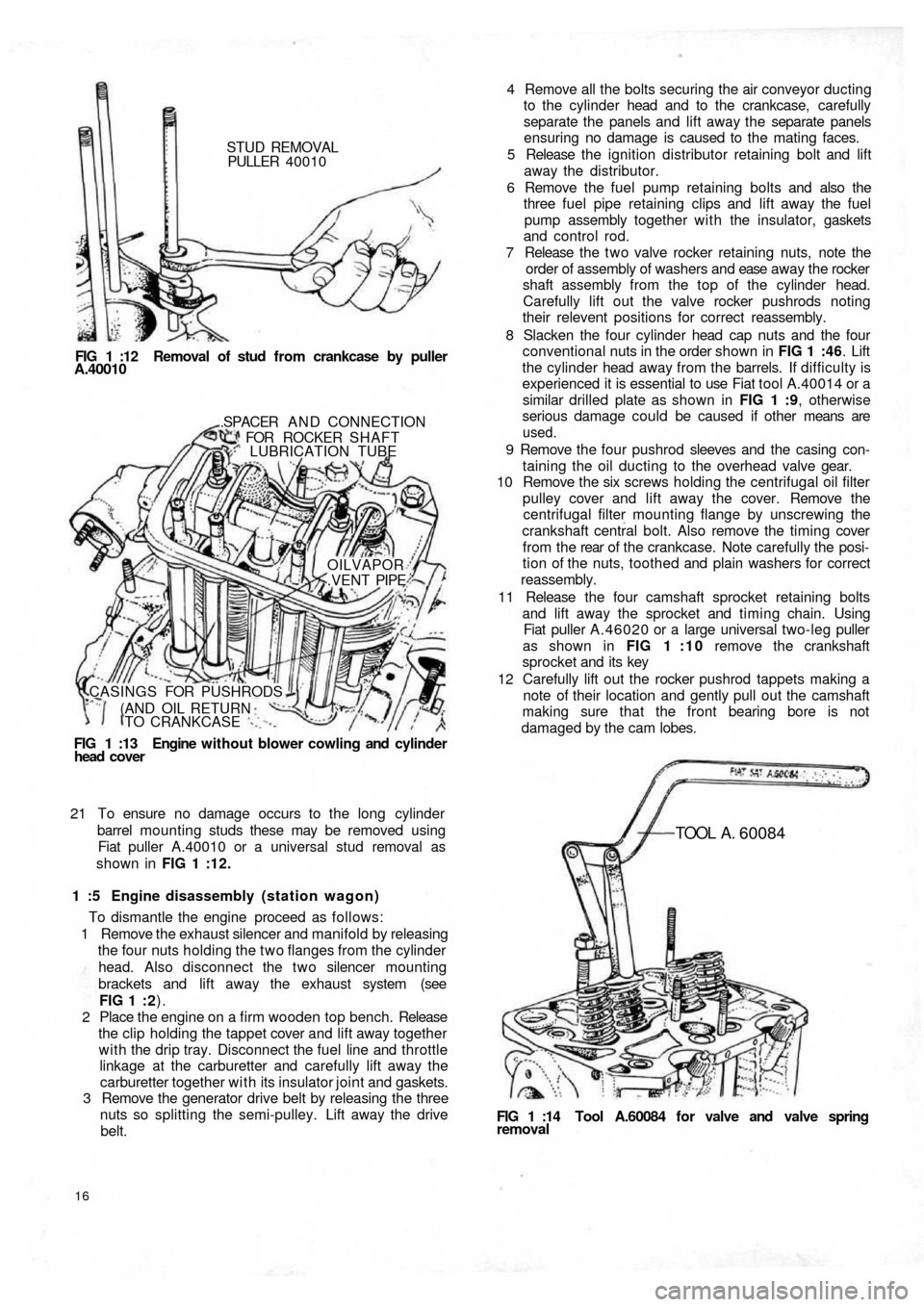
FIG 1 :12 Removal of stud from crankcase by puller
A.40010
FIG 1 :13 Engine without blower cowling and cylinder
head cover.SPACER A N D CONNECTION
FOR ROCKER SHAFT
LUBRICATION TUBE
OILVAPOR
.VENT PIPE
CASINGS FOR PUSHRODS
(AND OIL RETURN
TO CRANKCASE
21 To ensure no damage occurs to the long cylinder
barrel mounting studs these may be removed using
Fiat puller A.40010 or a universal stud removal as
shown in FIG 1 :12.
1 :5 Engine disassembly (station wagon)
To dismantle the engine proceed as follows:
1 Remove the exhaust silencer and manifold by releasing
the four nuts holding the two flanges from the cylinder
head. Also disconnect the two silencer mounting
brackets and lift away the exhaust system (see
FIG 1 : 2).
2 Place the engine on a firm wooden top bench. Release
the clip holding the tappet cover and lift away together
with the drip tray. Disconnect the fuel line and throttle
linkage at the carburetter and carefully lift away the
carburetter together with its insulator joint and gaskets.
3 Remove the generator drive belt by releasing the three
nuts so splitting the semi-pulley. Lift away the drive
belt.
16
FIG 1 :14 Tool A.60084 for valve and valve springremoval
TOOL A . 60084
4 Remove all the bolts securing the air conveyor ducting
to the cylinder head and to the crankcase, carefully
separate the panels and lift away the separate panels
ensuring no damage is caused to the mating faces.
5 Release the ignition distributor retaining bolt and lift
away the distributor.
6 Remove the fuel pump retaining bolts and also the
three fuel pipe retaining clips and lift away the fuel
pump assembly together with the insulator, gaskets
and control rod.
7 Release the t w o valve rocker retaining nuts, note the
order of assembly of washers and ease away the rocker
shaft assembly from the top of the cylinder head.
Carefully lift out the valve rocker pushrods noting
their relevent positions for correct reassembly.
8 Slacken the four cylinder head cap nuts and the four
conventional nuts in the order shown in FIG 1 :46. Lift
the cylinder head away from the barrels. If difficulty is
experienced it is essential to use Fiat tool A.40014 or a
similar drilled plate as shown in FIG 1 :9, otherwise
serious damage could be caused if other means are
used.
9 Remove the four pushrod sleeves and the casing con-
taining the oil ducting to the overhead valve gear.
10 Remove the six screws holding the centrifugal oil filter
pulley cover and lift away the cover. Remove the
centrifugal filter mounting flange by unscrewing the
crankshaft central bolt. Also remove the timing cover
f r o m t h e rear of t h e crankcase. Note carefully the posi-
tion of the nuts, toothed and plain washers for correct
reassembly.
11 Release the four camshaft sprocket retaining bolts
and lift away the sprocket and timing chain. Using
Fiat puller A.46020 or a large universal two-leg puller
as shown in FIG 1 : 1 0 remove the crankshaft
sprocket and its key
12 Carefully lift out the rocker pushrod tappets making a
note of their location and gently pull out the camshaft
making sure that the front bearing bore is not
damaged by the cam lobes.
Page 25 of 128
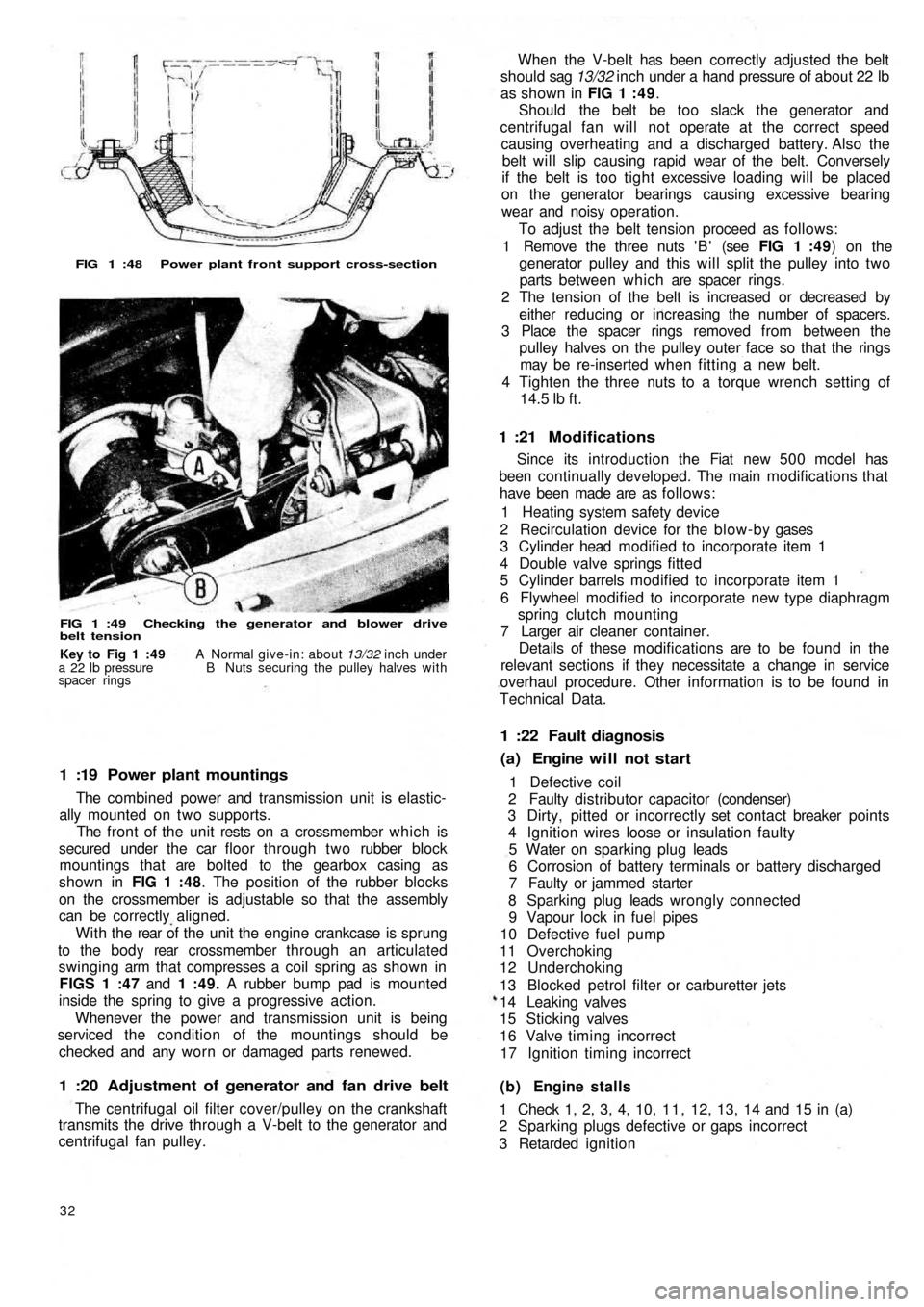
FIG 1 :48 Power plant front support cross-section
FIG 1 :49 Checking the generator and blower drive
belt tension
1 :19 Power plant mountings
The combined power and transmission unit is elastic-
ally mounted on two supports.
The front of the unit rests on a crossmember which is
secured under the car floor through two rubber block
mountings that are bolted to the gearbox casing as
shown in FIG 1 :48. The position of the rubber blocks
on the crossmember is adjustable so that the assembly
can be correctly aligned.
W i t h t h e rear of the unit the engine crankcase is sprung
to the b o d y rear crossmember through an articulated
swinging arm that compresses a coil spring as shown in
FIGS 1 :47 and 1 :49. A rubber bump pad is mounted
inside the spring to give a progressive action.
Whenever the power and transmission unit is being
serviced the condition of the mountings should be
checked and any worn or damaged parts renewed.
1 :20 Adjustment of generator and fan drive belt
The centrifugal oil filter cover/pulley on the crankshaft
transmits the drive through a V-belt to the generator and
centrifugal fan pulley.
32
(b) Engine stalls
1 Check 1, 2, 3, 4, 10, 1 1 , 12, 13, 14 and 15 in (a)
2 Sparking plugs defective or gaps incorrect
3 Retarded ignition 1 Defective coil
2 Faulty distributor capacitor (condenser)
3 Dirty, pitted or incorrectly set contact breaker points
4 Ignition wires loose or insulation faulty
5 Water on sparking plug leads
6 Corrosion of battery terminals or battery discharged
7 Faulty or jammed starter
8 Sparking plug leads wrongly connected
9 Vapour lock in fuel pipes
10 Defective fuel pump
11 Overchoking
12 Underchoking
13 Blocked petrol filter or carburetter jets
14 Leaking valves
15 Sticking valves
16 Valve timing incorrect
17 Ignition timing incorrect
(a) Engine will not start 1 :22 Fault diagnosis
Since its introduction the Fiat new 5 0 0 model has
been continually developed. The main modifications that
have been made are as follows:
1 Heating system safety device
2 Recirculation device for the blow-by gases
3 Cylinder head modified to incorporate item 1
4 Double valve springs fitted
5 Cylinder barrels modified to incorporate item 1
6 Flywheel modified to incorporate new type diaphragm
spring clutch mounting
7 Larger air cleaner container.
Details of these modifications are to be found in the
relevant sections if they necessitate a change in service
overhaul procedure. Other information is to be found in
Technical Data.
1 :21 Modifications
When the V-belt has been correctly adjusted the belt
should sag 13/32 inch under a hand pressure of about 22 lb
as shown in FIG 1 : 4 9.
Should the belt be too slack the generator and
centrifugal fan will not operate at the correct speed
causing overheating and a discharged battery. Also the
belt will slip causing rapid wear of the belt. Conversely
if the belt is too tight excessive loading will be placed
on the generator bearings causing excessive bearing
wear and noisy operation.
To adjust the belt tension proceed as follows:
1 Remove the three nuts ' B ' (see FIG 1 :49) on the
generator pulley and this will split the pulley into two
parts between which are spacer rings.
2 The tension of the belt is increased or decreased by
either reducing or increasing the number of spacers.
3 Place the spacer rings removed from between the
pulley halves on the pulley outer face so that the rings
may be re-inserted when fitting a new belt.
4 Tighten the three nuts to a torque wrench setting of
14.5
lb ft.
Key to Fig 1 :49 A Normal give-in: about 13/32 inch under
a 22 Ib pressure B Nuts securing the pulley halves with
spacer rings
Page 28 of 128
CHAPTER 2
THE FUEL SYSTEM
2:1 Description
2 : 2 Fuel pump operating principles
2 : 3 Routine maintenance
2 : 4 Pump removal, dismantling and examination
2 : 5 Reassembly, installation and adjustment
2 : 6 Carburetter operation and adjustment,
Weber 26.1MB2 : 7 Modifications
2 : 8 Carburetter operation and adjustment,
Weber 26.OC
2 :9 Air cleaner
2 : 1 0 B l o w - b y gases recirculation device
2:11 Fuel tank
2:12 Fault diagnosis
2:1 Description
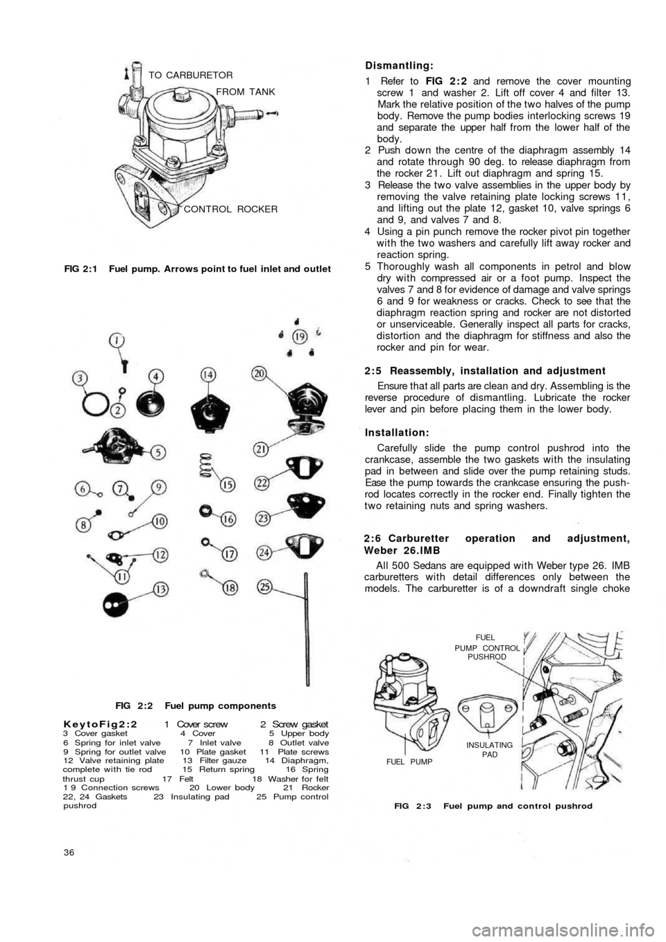
All the new 500 models use a mechanical diaphragm
fuel feed pump as shown in FIG 2 : 1. Four types of
carburetter are fitted depending on the model to which
the engine is installed. Each carburetter operation and
adjustment is fully described, together with details of the
recirculation device for blow-by gases and o i l vapours.
2 : 2 Fuel pump operating principles
Refer to FIG 2 : 2. An eccentric on the rotating camshaft
actuates the operating rocker 21 via a pushrod 25 which
depresses the diaphragm 14 and so creates a depression
in the pumping chamber located in upper body 5. Under
atmospheric pressure, petrol passes through the pipeline
connection and inlet valve into the pumping chamber.
The return spring 15 then raises the diaphragm, expelling
the petrol through the outlet valve and pipeline to the
carburetter float chamber.
When the float chamber is full, the pressure in the pipe-
line and pumping chamber holds the diaphragm depressed
against the tension of the return spring.2 : 3 Routine maintenance
A poor delivery of fuel to the carburetter may be due to
a fault in the fuel pump or related lines. Periodically the
pump body screws 19 (see FIG 2 : 2) and upper cover
screw 1 should be checked for tightness. The fuel pump
lines should be disconnected and checked for freedom of
restriction, chafing and loose connections. The fuel pump
filter should be removed and cleaned periodically.
2:4 Pump removal, dismantling and examination
The pump is located on the carburetter side of the
engine crankcase (sedan) or under the generator at the
front of the crankcase (station wagon).
Removal:
1 Disconnect the fuel pipe from the tank to stop petrol
syphoning out of the tank and then release the fuel
inlet and outlet pipes from the pump body.
2 Remove the t w o nuts and washers holding pump to
crankcase.
3 Carefully lift away the pump, gaskets and insulating pad
from the crankcase (see FIG 2 : 3).
F50035
Page 29 of 128
CONTROL ROCKER FROM TANK TO CARBURETOR
FIG 2 : 1 Fuel pump. Arrows point to fuel inlet and outlet
FIG 2 : 2 Fuel pump components
KeytoFig2:2 1 Cover screw 2 Screw gasket3 Cover gasket 4 Cover 5 Upper body
6 Spring for inlet valve 7 Inlet valve 8 Outlet valve
9 Spring for outlet valve 10 Plate gasket 11 Plate screws
12 Valve retaining plate 13 Filter gauze 14 Diaphragm,
complete with tie rod 15 Return spring 16 Spring
thrust cup 17 Felt 18 Washer for felt
1 9 Connection screws 20 Lower body 21 Rocker
22, 24 Gaskets 23 Insulating pad 25 Pump control
pushrod
36
FIG 2 : 3 Fuel pump and control pushrod
FUELPUMP CONTROLPUSHROD
INSULATING
PAD
FUEL PUMP
A l l 500 Sedans are equipped with Weber type 26. IMB
carburetters w i t h detail differences only between the
models. The carburetter is of a downdraft single choke 2 : 6 Carburetter operation and adjustment,
Weber 26.IMB Carefully slide the pump control pushrod into the
crankcase, assemble the t w o gaskets w i t h the insulating
pad in between and slide over the pump retaining studs.
Ease t h e p u m p towards the crankcase ensuring the push-
rod locates correctly in the rocker end. Finally tighten the
two retaining nuts and spring washers. Installation:Ensure t h a t all parts are clean and dry. Assembling is the
reverse procedure of dismantling. Lubricate the rocker
lever and pin before placing them in the lower body. 2 : 5 Reassembly, installation and adjustment 1 Refer to FIG 2 : 2 and remove the cover mounting
screw 1 and washer 2. Lift off cover 4 and filter 13.
Mark the relative position of the two halves of the pump
body. Remove the pump bodies interlocking screws 19
and separate the upper half from the lower half of the
body.
2 Push down the centre of the diaphragm assembly 14
and rotate through 90 deg. to release diaphragm from
the rocker 2 1 . Lift out diaphragm and spring 15.
3 Release the t w o valve assemblies in the upper body by
removing the valve retaining plate locking screws 1 1 ,
and lifting out the plate 12, gasket 10, valve springs 6
and 9, and valves 7 and 8.
4 Using a pin punch remove the rocker pivot pin together
w i t h the t w o washers and carefully lift away rocker and
reaction spring.
5 Thoroughly wash all components in petrol and
blow
dry with compressed air or a foot pump. Inspect the
valves 7 and 8 for evidence of damage and valve springs
6 and 9 for weakness or cracks. Check to see that the
diaphragm reaction spring and rocker are not distorted
or unserviceable. Generally inspect all parts for cracks,
distortion and the diaphragm for stiffness and also the
rocker and pin for wear. Dismantling:
Page 30 of 128
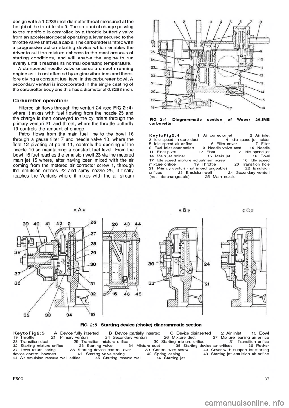
FIG 2:5 Starting device (choke) diagrammatic section
KeytoFig2:5 A Device fully inserted B Device partially inserted C Device disinserted 2 Air inlet 16 Bowl
19 Throttle 21 Primary venturi 24 Secondary venturi 26 Mixture duct 27 Mixture leaning air orifice
28 Transition duct 29 Transition mixture orifice 30 Starting mixture orifice 31 Transition orifice
32 Starting mixture orifice 33 Starting valve 34 Mixture duct 35 Starting device air orifices 36 Rocker
37 Lever return spring 38 Starting device control lever 39 Control wire screw 40 Cover with support for starting
device control bowden 41 Starting valve spring 42 Spring casing. 43 Starting jet emulsion air orifice
44 Air emulsion reserve well orifice 45 Starting reserve well 46 Starting jet
F50037
FIG 2 : 4 Diagrammatic section of Weber 26.IMB
carburetter
KeytoFig2:4 1 Air corrector jet 2 Air inlet
3 Idle speed mixture duct 4 Idle speed jet holder
5 Idle speed air orifice 6 Filter cover 7 Filter
8 Fuel inlet connection 9 Needle valve seat 10 Needle
11 Float pivot 12 Float 13 Idle speed jet
14 Main jet holder 15 Main jet 16 Bowl
17 Idle speed mixture adjustment screw 18 Idle speed
mixture orifice 19 Throttle 20 Transition hole
21 Primary venturi (not interchangeable) 22 Emulsion
orifices 23 Emulsion well 24 Secondary venturi
(not interchangeable) 25 Main nozzle
design with a 1.0236 inch diameter throat measured at the
height of the throttle shaft. The amount of charge passing
to the manifold is controlled by a throttle butterfly valve
from an accelerator pedal operating a lever secured to the
throttle valve shaft via a cable. The carburetter is fitted with
a progressive action starting device which enables the
driver to suit the mixture richness to the most arduous of
starting conditions, and will enable the engine to run
evenly until it reaches its normal operating temperature.
A dampened needle valve ensures a smooth running
engine as it is not affected by engine vibrations and there-
fore giving a constant fuel level in the carburetter bowl. A
secondary venturi is incorporated in the single casting of
the carburetter body and this has a diameter of 0.8268 inch.
Carburetter operation:
Filtered air flows through the venturi 24 (see FIG 2 :4)
where it mixes w i t h fuel flowing from the nozzle 25 and
the charge is then conveyed to the cylinders through the
primary venturi 21 and throat, where the throttle butterfly
19 controls the amount of charge.
Petrol flows from the main fuel line to the bowl 16
through a gauze filter 7 and needle valve 10, where the
float 12 pivoting at point 1 1 , controls the opening of the
needle 10 so maintaining a constant fuel level. From the
bowl 16 fuel reaches the emulsion well 23 via the metered
main jet 15 where, after having been mixed with the air
coming from the metered air corrector screw 1, through
the emulsion orifices 22 and spray nozzle 25, it finally
reaches the Venturis where it mixes w i t h the air stream
Page 33 of 128
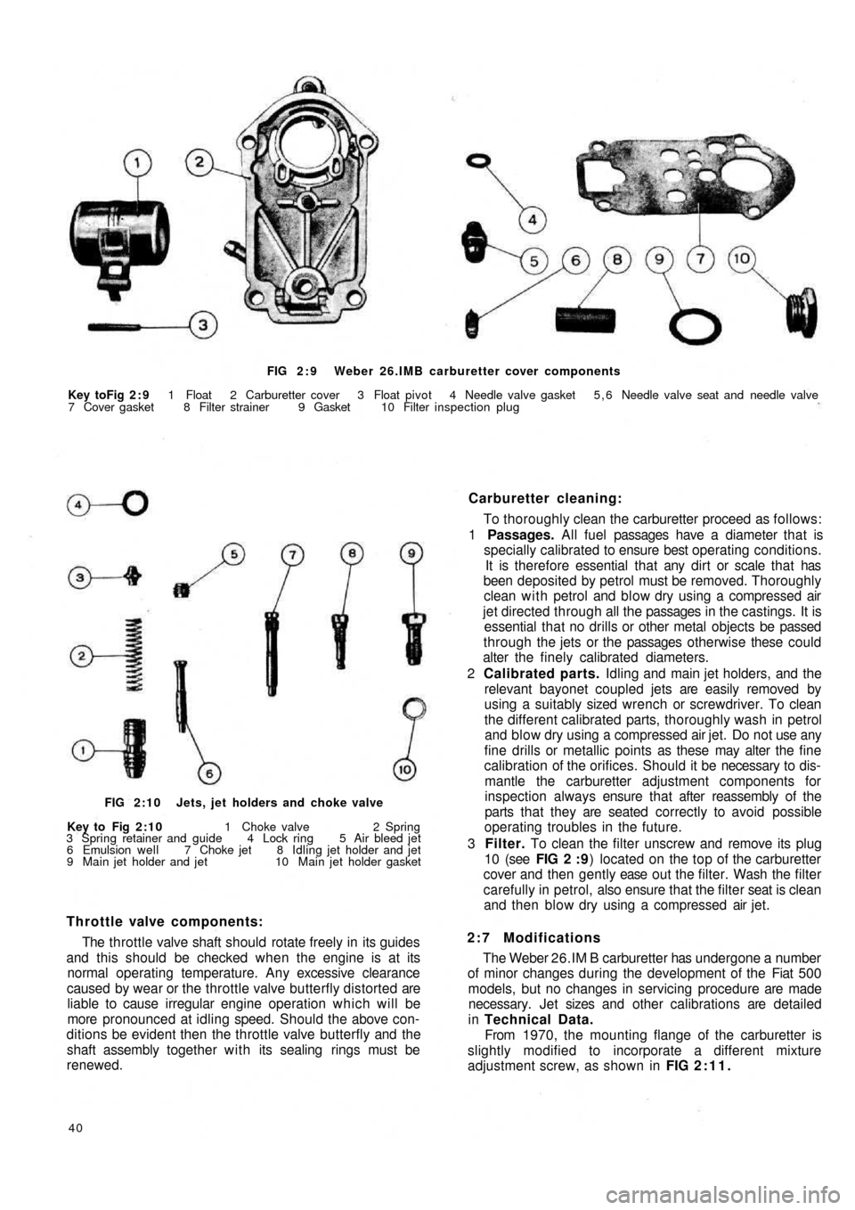
FIG 2 : 9 Weber 26.IMB carburetter cover components
Key toFig 2 : 9 1 Float 2 Carburetter cover 3 Float pivot 4 Needle valve gasket 5 , 6 Needle valve seat and needle valve
7 Cover gasket 8 Filter strainer 9 Gasket 10 Filter inspection plug
Carburetter cleaning:
To thoroughly clean the carburetter proceed as follows:
1 Passages. All fuel passages have a diameter that is
specially calibrated to ensure best operating conditions.
It is therefore essential that any dirt or scale that has
been deposited by petrol must be removed. Thoroughly
clean with petrol and blow dry using a compressed air
jet directed through all the passages in the castings. It is
essential that no drills or other metal objects be passed
through the jets or the passages otherwise these could
alter the finely calibrated diameters.
2 Calibrated parts. Idling and main jet holders, and the
relevant bayonet coupled jets are easily removed by
using a suitably sized wrench or screwdriver. To clean
the different calibrated parts, thoroughly wash in petrol
and blow dry using a compressed air jet. Do not use any
fine drills or metallic points as these may alter the fine
calibration of the orifices. Should it be necessary to dis-
mantle the carburetter adjustment components for
inspection always ensure that after reassembly of the
parts that they are seated correctly to avoid possible
operating troubles in the future.
3 Filter. To clean the filter unscrew and remove its plug
10 (see FIG 2 : 9) located on the top of the carburetter
cover and then gently ease o u t t h e filter. Wash the filter
carefully in petrol, also ensure that the filter seat is clean
and then blow dry using a compressed air jet.
2:7 Modifications
The Weber 26.IM B carburetter has undergone a number
of minor changes during the development of the Fiat 500
models, but no changes in servicing procedure are made
necessary. Jet sizes and other calibrations are detailed
in Technical Data.
From 1970, the mounting flange of the carburetter is
slightly modified to incorporate a different mixture
adjustment screw, as shown in FIG 2:11.
40
Throttle valve components:
The throttle valve shaft should rotate freely in its guides
and this should be checked when the engine is at its
normal operating temperature. Any excessive clearance
caused by wear or the throttle valve butterfly distorted are
liable to cause irregular engine operation which will be
more pronounced at idling speed. Should the above con-
ditions be evident then the throttle valve butterfly and the
shaft assembly together with its sealing rings must be
renewed.
FIG 2:10 Jets, jet holders and choke valve
Key to Fig 2:10 1 Choke valve 2 Spring
3 Spring retainer and guide 4 Lock ring 5 Air bleed jet
6 Emulsion well 7 Choke jet 8 Idling jet holder and jet
9 Main jet holder and jet 10 Main jet holder gasket
Page 35 of 128
3938
28 29 30A3132 33
28 29 30 3.1B28
29 30 31C
34 34
34
37 36 35 23
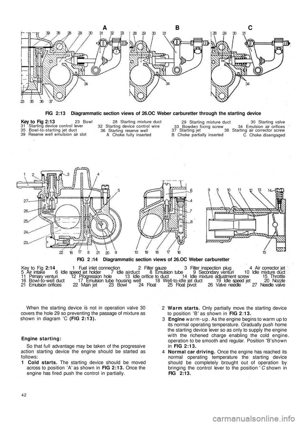
FIG 2:13 Diagrammatic section views of 26.OC Weber carburetter through the starting device
1
2.34
5
27
26.
25,
24.
23.
22
1617
8
21
209
_6
.4
7
.8
10 19 1817
16 1595
1011
1213
14.
FIG 2 :14 Diagrammatic section views of 26.OC Weber carburetter
Key to Fig 2:14 1 Fuel inlet connection 2 Filter gauze 3 Filter inspection plug 4 Air corrector jet
5 Air intake 6 Idle speed jet holder 7 Idle airduct 8 Emulsion tube 9 Secondary venturi 10 Idle mixture duct
11 Primary venturi 12 Progression hole 13 Idle orifice to duct 14 Idle mixture adjustment screw 15 Throttle
16 B o w l - t o - w e l l duct 17 Emulsion tube housing well 18 Well-to-idle jet duct 19 Idle speed jet 20 Nozzle
21 Emulsion orifices 22 Main jet 23 Bowl 24 Float 25 Float pivot 26 Valve needle 27 Needle valve
When the starting device is not in operation valve 30
covers the hole 29 so preventing the passage of mixture as
shown in diagram 'C (FIG 2:13).
Engine starting:
So that full advantage may be taken of the progressive
action starting device the engine should be started as
follows:
1 Cold starts. The starting device should be moved
across to position 'A' as shown in FIG 2:13. Once the
engine has fired push the control in partially.
42
2 Warm starts. Only partially move the starting device
to position ' B ' as shown in FIG 2:13.
3 Engine warm-up. As the engine begins to warm up to
its normal operating temperature. Gradually push home
the starting device lever so as only to supply the engine
with the richened charge enabling the cold engine.
operation to be smooth and regular. Position ' B ' s h o w n
in FIG 2:13.
4 Normal car driving. Once the engine has reached its
normal operating temperature the starting device
should be completely brought out of operation by
bringing the control lever to the position C shown in
FIG 2:13. Key t o Fig 2 : 1 3
23 Bowl 28 Starting mixture duct
29 Starting mixture duct30 Starting valve
34 Emulsion air orifices
38 Starting air corrector screw
C Choke disengaged B Choke partially inserted 37 Starting jet33 Bowden fixing screw
A Choke fully inserted 36 Starting reserve well 32 Starting device control wire 31 Starting device control lever
35 Bowl-to-starting jet duct
39 Reserve well emulsion air slot
Page 36 of 128
1
14,5
7,52 9 48 35
76
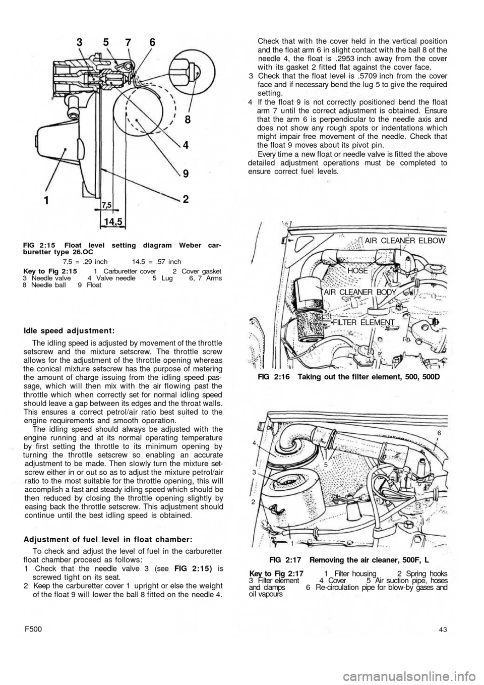
FIG 2:15 Float level setting diagram Weber car-
buretter type 26.OC
7.5 = .29 inch 14.5 = .57 inch
Key to Fig 2:15 1 Carburetter cover 2 Cover gasket
3 Needle valve 4 Valve needle 5 Lug 6, 7 Arms
8 Needle ball 9 Float
Idle speed adjustment:
The idling speed is adjusted by movement of the throttle
setscrew and the mixture setscrew. The throttle screw
allows for the adjustment of the throttle opening whereas
the conical mixture setscrew has the purpose of metering
the amount of charge issuing from the idling speed pas-
sage, which will then mix with the air flowing past the
throttle which when correctly set for normal idling speed
should leave a gap between its edges and the throat walls.
This ensures a correct petrol/air ratio best suited to the
engine requirements and smooth operation.
The idling speed should always be adjusted with the
engine running and at its normal operating temperature
by first setting the throttle to its minimum opening by
turning the throttle setscrew so enabling an accurate
adjustment to be made. Then slowly turn the mixture set-
screw either in or out so as to adjust the mixture petrol/air
ratio to the most suitable for the throttle opening, this will
accomplish a fast and steady idling speed which should be
then reduced by closing the throttle opening slightly by
easing back the throttle setscrew. This adjustment should
continue until the best idling speed is obtained.
Adjustment of fuel level in float chamber:
To check and adjust the level of fuel in the carburetter
float chamber proceed as follows:
1 Check that the needle valve 3 (see FIG 2:15) is
screwed tight on its seat.
2 Keep the carburetter cover 1 upright or else the weight
of the float 9 will lower the ball 8 fitted on the needle 4.
F50043
Key to Fig 2:17 1 Filter housing 2 Spring hooks
3 Filter element 4 Cover 5 Air suction pipe, hoses
and clamps 6 Re-circulation pipe for blow-by gases and
oil vapoursFIG 2:17 Removing the air cleaner, 500F, L
2
1 3
4.
6
5
FIG 2:16 Taking out the filter element, 500, 500D AIR CLEANER ELBOW
HOSE
AIR CLEANER BODY
FILTER ELEMENT Check that with the cover held in the vertical position
and the float arm 6 in slight contact with the ball 8 of the
needle 4, the float is .2953 inch away from the cover
w i t h its gasket 2 fitted flat against the cover face.
3 Check that the float level is .5709 inch from the cover
face and if necessary bend the lug 5 to give the required
setting.
4 If the float 9 is not correctly positioned bend the float
arm 7 until the correct adjustment is obtained. Ensure
that the arm 6 is perpendicular to the needle axis and
does not show any rough spots or indentations which
might impair free movement of the needle. Check that
the float 9 moves about its pivot pin.
Every time a new float or needle valve is fitted the above
detailed adjustment operations must be completed to
ensure correct fuel levels.