steering FIAT 500 1957 1.G Workshop Manual
[x] Cancel search | Manufacturer: FIAT, Model Year: 1957, Model line: 500, Model: FIAT 500 1957 1.GPages: 128, PDF Size: 9.01 MB
Page 80 of 128
CHAPTER 8
FRONT SUSPENSION AND HUBS
8:1
8:2
8:3
8:4
8:5
8:6Description
Front suspension removal and dismantling
Leaf spring
Swinging arms
Kingpin housing
Steering knuckle and wheel hub
8:1 Description
The independent front suspension assembly fitted to
the 'new 500' range comprises a transverse leaf spring
which is anchored to the body through two rubber
mountings and kingpins through 'estendblocks' as
shown in FIG 8:1. The leaf spring also acts as an anti-
roll bar which gives normal spring reaction even when the
front road wheels encounter a rough road surface.
Special polyethylene insulating strips are fitted
between the five springs leaves which are all clamped
together by t w o rubber cushioned clamps.
Upper movement of the kingpins in the swinging arm
is obtained by 'estendblocks'. The half arms are anchored
to the body as shown in FIG 8 : 3 and pivot on their pins
through rubber bushes. Double acting hydraulic shock
absorbers are fitted to the kingpin housings at the lower
end and anchored at the top to the vehicle body. Two
rubber buffers are secured to brackets mounted onto the
body to limit the spring oscillations. The spring centre
bolt is also fitted with a rubber pad.
8 : 2 Front suspension removal and
dismantling
To remove the front suspension assembly proceed as
follows:
F50087
1 Remove the hub caps and carefully slacken the road
wheel retaining bolts. Using a garage hydraulic jack
raise the front of the vehicle and place on firmly
based stands. Remove the road wheels.
2 Disconnect the steering linkages from the pitman arm,
the drag link and the steering knuckle arms.
3 Remove the shock absorber upper mounting nut from
the body, lift away the half rubber bush and push d o w n
the outer cylinder.
4 Blank off the brake fluid reservoir outlet by inserting
a suitable wooden peg through the reservoir filler
opening and disconnect the brake hydraulic lines at
the wheel cylinders.
5 Fit Fiat crossbeam Arr.2072 under the leaf spring
and support this, using a garage hydraulic jack.
6 Remove the self-locking nut securing the leaf spring
to the kingpin housing and ease o u t the spring
mounting bolt taking care not to damage the thread.
Also remove the nuts securing the swinging arm pin
to studs on the body and remove the swinging arm
assembly. Carefully lift out the adjusting shims and
spacers from the studs making a careful note of the
number of the shims and their locations.
7 Remove the nuts securing the leaf spring elastic
mounting to the body (see FIG 8 : 4) , and lower the 8:7
8:8
8:9
8:10
8:11Hydraulic damper
Front suspension assembly and
installation
Steering geometry
Modifications
Fault diagnosis
Page 84 of 128
2 Check that the surface of the pin that is in contact with
the camber and castor adjuster shims does not show
any signs of indentation or roughness which could
affect the accuracy of adjustment on reassembly. If
there are any signs of rust or small markings these
should be smoothed out using a file.
3 Inspect the condition of the half arm bushes, the inner
surface of which must not show signs of seizure and
the clearance of the bush to pin must not be greater
than .01 57 inch. Upon initial assembly the fit clearance
is .00059 to .0059 inch. Ensure t h a t the rubber parts
of the bush are not torn, cracked or show signs of
weakness which, if evident, must be renewed.
4 Use Fiat tool A.66058 or a suitably sized drift for
refitting the rubber bushes into the swinging arms.
Upon reassembly it should be observed that the
tightening of the two swinging arms m o u n t i n g nuts 5
(see FIG 8 : 3) , must be carried out whilst keeping
the axis of the swinging arm and the pin hole for the
screws 7 on the same plane otherwise distortion can
occur.
8 : 5 Kingpin housing
1 To remove and replace the 'estendblocks' use Fiat
tool A.66056 as shown in FIG 8 : 8. Ensure t h a t the
'estendblocks' is not worn and that there are no signs
of seizure on its inner surface, or that the rubber has
hardened. Renew if necessary.
2 Check that the kingpin to bush clearance is not
greater than .0079 inch. The clearance when fitted
new is .00063 to .00213 inch. If the clearance is
excessive the t w o bushes must be renewed and also
the kingpin if excessive wear is evident. To remove and
refit the kingpin bushes use Fiat tool A.66016 and
after reassembly the bushes must be accurately
refaced using a reamer set to a diameter of .5912 to
.5922 inch. If considered necessary use Fiat Fixture
C.1004 to check that the kingpin housing has not been
distorted which, if evident, the housing must be
renewed.
3 Whilst the kingpin assembly is being inspected ensure
that the lubrication hole is free to allow the passage of
oil.
4 To prevent incorrect loading of the 'estendblocks' that
is press fitted into the kingpin housing, the housing
to swinging arm pin nut must be tightened with the
parts so arranged that the angle between the swinging
arm plane and the housing axis is approximately
95 deg. as shown in FIG 8:14.
8:6 Steering knuckle and wheel hub
Dismantling:
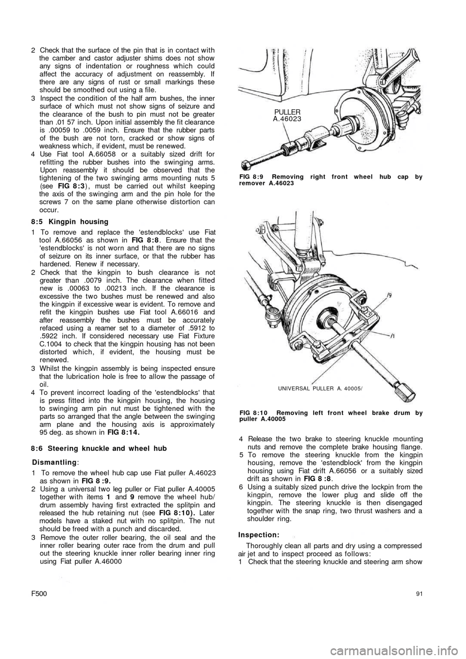
1 To remove the wheel hub cap use Fiat puller A.46023
as shown in FIG 8 : 9 .
2 Using a universal t w o leg puller or Fiat puller A.40005
together with items 1 and 9 remove the wheel hub/
drum assembly having first extracted the splitpin and
released the hub retaining nut (see FIG 8:10). Later
models have a staked nut w i t h no splitpin. The nut
should be freed with a punch and discarded.
3 Remove the outer roller bearing, the oil seal and the
inner roller bearing outer race from the drum and pull
out the steering knuckle inner roller bearing inner ring
using Fiat puller A.46000
F500PULLER
A.46023
FIG 8 : 9 Removing right front wheel hub cap by
remover A.46023
UNIVERSAL PULLER A. 40005/
FIG 8:10 Removing left front wheel brake drum by
puller A.40005
4 Release the t w o brake to steering knuckle mounting
nuts and remove the complete brake housing flange.
5 To remove the steering knuckle from the kingpin
housing, remove the 'estendblock' from the kingpin
housing using Fiat drift A.66056 or a suitably sized
drift as shown in FIG 8 : 8.
6 Using a suitably sized punch drive the lockpin from the
kingpin, remove the lower plug and slide off the
kingpin. The steering knuckle is then disengaged
together with the snap ring, two thrust washers and a
shoulder ring.
Inspection:
Thoroughly clean all parts and dry using a compressed
air jet and to inspect proceed as follows:
1 Check that the steering knuckle and steering arm show
91
Page 85 of 128
1
2
6
3
8
11
13
17
19
22
25
27
29
31
33
36
35 323430 28
26
24232120 ,1816 15 14 12 10 .9 .15 4
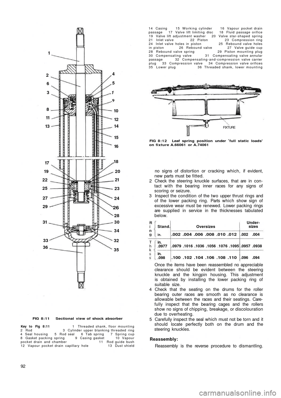
FIG 8:11 Sectional view of shock absorber
Key to Fig 8:11 1 Threaded shank, floor mounting
2 R o d 3 Cylinder upper blanking threaded ring
4 Seal housing 5 Rod seal 6 Tab spring 7 Spring cup
8 Gasket packing spring 9 Casing gasket 10 Vapour
pocket drain and chamber 11 Rod guide bush
12 Vapour pocket drain capillary hole 13 Dust shield
92
14 Casing 15 Working cylinder 16 Vapour pocket drain
passage 17 Valve lift limiting disc 18 Fluid passage orifice
19 Valve lift adjustment washer 20 Valve star-shaped spring
21 Inlet valve 22 Piston 23 Compression ring
24 Inlet valve holes in piston 25 Rebound valve holes
in piston 26 Rebound valve 27 Valve guide cup
28 Rebound valve spring 29 Piston mounting plug
30 Compensating valve 31 Compensating valve annular
passage 32 Compensating-and-compression valve carrier
plug 33 Compression valve 34 Compression valve orifices
35 Lower plug 36 Threaded shank, lower mounting
FIXTURE
FIG 8:12 Leaf spring position under full static loads'
on fixture A.66061 or A.74061
no signs of distortion or cracking which, if evident,
new parts must be fitted.
2 Check the steering knuckle surfaces, that are in con-
tact with the bearing inner races for any signs of
scoring or seizure.
3 Inspect the condition of the two upper thrust rings and
of the lower packing ring. Parts which show sign of
excessive wear must be renewed. Lower packing rings
are supplied in service in the thicknesses tabulated
below.
Once the items have been reassembled no appreciable
clearance should be evident between the steering
knuckle and the kingpin housing. This adjustment
is obtained by installing the lower packing ring of
suitable size.
4 Check that the seating on the drums for the roller
bearing outer races are smooth as no clearance is
allowable between the races and their seatings. Care-
fully inspect that the bearing cages and the rollers
show no signs of chipping, breakage, or discolouration
due to overheating.
5 Carefully inspect the seal which must not be torn and it
should locate perfectly both on the drum and the
steering knuckles.
Reassembly:
Reassembly is the reverse procedure to dismantling.
OversizesUnder-
sizes
.002 .004 .006 .008 .010 .012
.0979 .1016 .1036 .1056 .1076 .1095
.100 .102 .104 .106 .108 .110
.002 .004
.0957 .0938
.096 .094
Stand.
in.
in..0977
in..098
Page 87 of 128
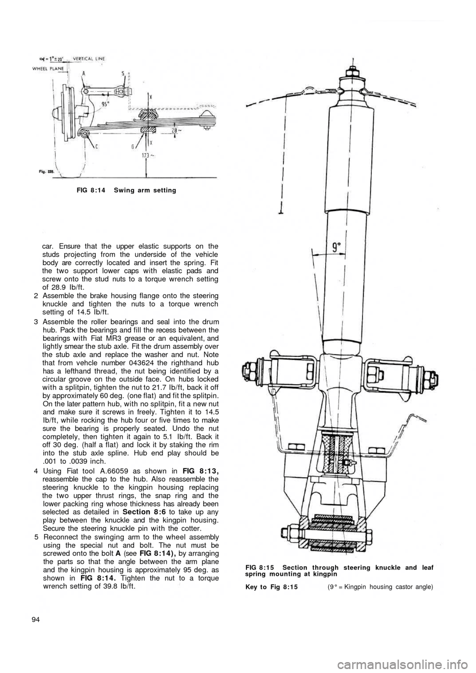
FIG 8:14 Swing arm setting
car. Ensure t h a t the upper elastic supports on the
studs projecting from the underside of the vehicle
body are correctly located and insert the spring. Fit
the two support lower caps w i t h elastic pads and
screw onto the stud nuts to a torque wrench setting
of 28.9 Ib/ft.
2 Assemble the brake housing flange onto the steering
knuckle and tighten the nuts to a torque wrench
setting of 14.5 Ib/ft.
3 Assemble the roller bearings and seal into the drum
hub. Pack the bearings and fill the recess between the
bearings w i t h Fiat MR3 grease or an equivalent, and
lightly smear the stub axle. Fit the drum assembly over
the stub axle and replace the washer and nut. Note
that from vehcle number 043624 the righthand hub
has a lefthand thread, the nut being identified by a
circular groove on the outside face. On hubs locked
with a splitpin, tighten the nut to 21.7 Ib/ft, back it off
by approximately 60 deg. (one flat) and fit the splitpin.
On the later pattern hub, with no splitpin, fit a new nut
and make sure it screws in freely. Tighten it to 14.5
Ib/ft, while rocking the hub four or five times to make
sure the bearing is properly seated. Undo the nut
completely, then tighten it again to 5.1 Ib/ft. Back it
off 30 deg. (half a flat) and lock it by staking the rim
into the stub axle spline. Hub end play should be
.001 to .0039 inch.
4 Using Fiat tool A.66059 as shown in FIG 8:13,
reassemble the cap to the hub. Also reassemble the
steering knuckle to the kingpin housing replacing
the t w o upper
thrust rings, the snap ring and the
lower packing ring whose thickness has already been
selected as detailed in Section 8:6 to take up any
play between the knuckle and the kingpin housing.
Secure the steering knuckle pin with the cotter.
5 Reconnect the swinging arm to the wheel assembly
using the special nut and bolt. The nut must be
screwed onto the bolt A (see FIG 8:14), by arranging
the parts so that the angle between the arm plane
and the kingpin housing is approximately 95 deg. as
shown in FIG 8:14. Tighten the nut to a torque
wrench setting of 39.8 Ib/ft.
94
Key to Fig 8:15(9° = Kingpin housing castor angle) FIG 8:15 Section through steering knuckle and leaf
spring mounting at kingpin
Page 88 of 128
VERTICAL LINE DB
S
EB
OIL SUMPF
GF
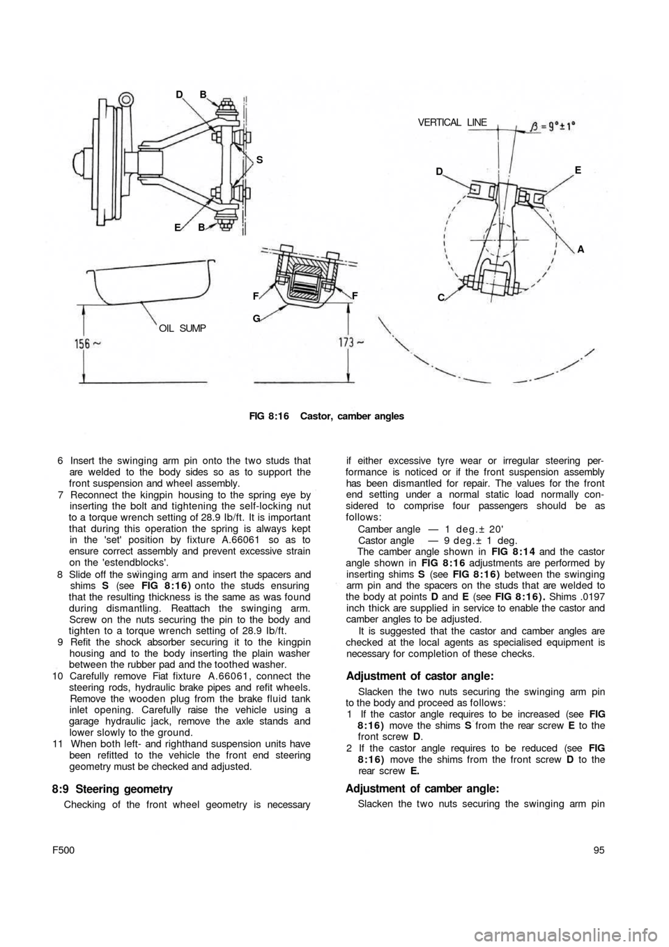
FIG 8:16 Castor, camber angles
6 Insert the swinging arm pin onto the two studs that
are welded to the body sides so as to support the
front suspension and wheel assembly.
7 Reconnect the kingpin housing to the spring eye by
inserting the bolt and tightening the self-locking nut
to a torque wrench setting of 28.9 Ib/ft. It is important
that during this operation the spring is always kept
in the 'set' position by fixture A.66061 so as to
ensure correct assembly and prevent excessive strain
on the 'estendblocks'.
8 Slide off the swinging arm and insert the spacers and
shims S (see FIG 8:16) onto the studs ensuring
that the resulting thickness is the same as was found
during dismantling. Reattach the swinging arm.
Screw on the nuts securing the pin to the body and
tighten to a torque wrench setting of 28.9 Ib/ft.
9 Refit the shock absorber securing it to the kingpin
housing and to the body inserting the plain washer
between the rubber pad and the toothed washer.
10 Carefully remove Fiat fixture A.66061, connect the
steering rods, hydraulic brake pipes and refit wheels.
Remove the wooden plug from the brake fluid tank
inlet opening. Carefully raise the vehicle using a
garage hydraulic jack, remove the axle stands and
lower slowly to the ground.
11 When both left- and righthand suspension units have
been refitted to the vehicle the front end steering
geometry must be checked and adjusted.
8:9 Steering geometry
Checking of the front wheel geometry is necessary
95
F500
if either excessive tyre wear or irregular steering per-
formance is noticed or if the front suspension assembly
has been dismantled for repair. The values for the front
end setting under a normal static load normally con-
sidered to comprise four passengers should be as
follows:
Camber angle — 1 d e g . ± 20'
Castor angle — 9 deg.± 1 deg.
The camber angle shown in FIG 8:14 and the castor
angle shown in FIG 8 : 1 6 adjustments are performed by
inserting shims S (see FIG 8 : 1 6 ) between the swinging
arm pin and the spacers on the studs that are welded to
the body at points D and E (see FIG 8:16). Shims .0197
inch thick are supplied in service to enable the castor and
camber angles to be adjusted.
It is suggested that the castor and camber angles are
checked at the local agents as specialised equipment is
necessary for completion of these checks.
Adjustment of castor angle:
Slacken the t w o nuts securing the swinging arm pin
to the body and proceed as follows:
1 If the castor angle requires to be increased (see FIG
8:16) move the shims S from the rear screw E to the
front screw D.
2 If the castor angle requires to be reduced (see FIG
8:16) move the shims from the front screw D to the
rear screw E.
Adjustment of camber angle:
Slacken the t w o nuts securing the swinging arm pin DE
A
C
Page 89 of 128
to the body and proceed as follows:
1 If the camber angle requires to be increased (see FIG
8:16) add the same number of shims S on both
screws D and E.
2 If the camber angle requires to be reduced (see FIG
8:16) remove the same number of shims from both
screws D and E.
The addition or removal of shims at the t w o points D
and E permits camber adjustment to be made without
any disturbing of the castor angle.
8:10 Modifications
Checking and adjusting castor and camber angles:
When checking the castor and camber angle the
static loading should be such that the distance between
the semi-elliptic spring mountings G (see FIG 8:16)
and the floor level to be approximately 6.81 inches, also a
distance between the lowermost portion of the sump and
the floor level of approximately 6.14 inch for the Model
500D. For the 500 Station Wagon version the distance
between centre rear bracket for jacking-up the vehicle
and the floor level should be approximately 8.90 inches.
All other front wheel alignment specifications are the
same as for the remaining 500 saloon models.
8:11 Fault diagnosis
(a) Wheel bounce
1 Tyre casing faulty
2 Uneven tyre pressures
3 Wheels out of balance
4 Semi-elliptic mounting spring worn5 Weak or seized shock absorber
6 Wheel rim or tyre misaligned
(b) Suspension noise
1 Lack of lubrication
2 Noisy or inoperative shock absorbers
3 Worn or loose wheel bearings
(c) Pull to one side
1 Low or uneven tyre pressures
2 Incorrect front wheel alignment
3 Suspension arms distorted
4 Inoperative shock absorbers
5 Brakes binding
(d) Excessive t y r e wear
1 Incorrect tyre rotation during servicing periods
2 Incorrect camber angle
3 Incorrect toe-in
4 Incorrect tyre inflation
5 Excessive play at wheel bearings
6 Wheel wobble
7 Stiff suspension arms
8 Brakes out of adjustment
(e) Wheel wobble
1 Uneven tyre pressures
2 Loose or worn wheel bearings
3 Inoperative shock absorbers
4 Loose steering knuckle or kingpin housing
5 Incorrect front wheel alignment
6 Control arm rubber bushings, or kingpin housing and
semi-elliptic spring 'estendblock' worn
96
Page 90 of 128
CHAPTER 9
THE STEERING SYSTEM
9 : 5 Relay lever and support
9 : 6 Steering rods
9 : 7 Front wheel toe-in
9 : 8 Fault diagnosis 9:1 Description
9 : 2 Steering wheel removal and refitting
9 : 3 Steering box removal and refitting
9 : 4 Steering box dismantling and reassembly
9:1 Description
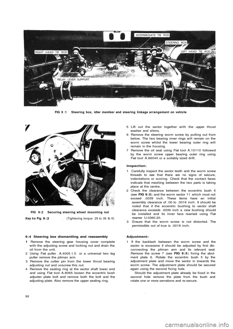
The steering gear fitted to the new 500 range of
vehicles is of the worm screw and sector type with a
steering ratio of 1:13. The steering gearbox is located on
the front lefthand side of the dash wall on the scuttle as
shown in FIG 9:1. The steering gear comprises a pitman
arm and relay lever pivoting on a pin supported on the
body. A central track rod connects the pitman arm to the
relay lever. T w o track rods connect the pitman arm and
relay lever to the knuckle arms.
9:2 Steering wheel removal and refitting
To remove the steering wheel proceed as follows:
1 Disconnect the battery positive terminal clamp and
remove the horn control from the steering wheel.
2 Remove the cable from the push button seating and the
cable insulation sleeve.
3 Using a suitably sized box spanner or Fiat wrench
A.8279 unscrew the steering wheel to shaft nut as
shown in FIG 9:2.
4 Using the palm of the hands against the back of the
steering wheel rim gently tap the steering wheel
forwards so releasing it from the inner shaft.
F50097 5 Reassembly is the reverse procedure to dismantling.
Care should be taken to ensure that the front wheels
are located in the straight ahead position when the
steering wheel is being replaced otherwise the steering
wheel spokes will not be correctly positioned.
9 : 3 Steering box removal and refitting
To remove the steering box from the vehicle proceed
as follows:
1 From inside the vehicle remove the steering column
clamp bolt 6 (see FIG 9 : 3) after flattening the lock-
washer 7.
2 From the underside of the vehicle remove the t w o
tie rod locking nuts from the pitman arm and then using
Fiat tool A.46006 or a suitable t w o leg puller withdraw
the pins from the seats.
3 Remove the three nuts holding the steering box to the
body panel. Ease out the worm screw from the
steering shaft and lift away the steering box.
4 To refit the steering box is the reverse procedure to
dismantling. The steering box to body mounting nuts
should be tightened to a torque wrench setting of
14 Ib/ft to 18 Ib/ft.
Page 91 of 128
RIGHT HAND TIE ROD
RELAY LEVER SUPPORTINTERMEDIATE TIE ROD!
STEERING BOX!
LEFT HAND TIE ROD
FIG 9 :1 Steering box, idler member and steering linkage arrangement on vehicle
FIG 9 : 2 Securing steering wheel mounting nut
Key
to Fig 9:2(Tightening torque: 29 to 36 Ib ft)
9 : 4 Steering box dismantling and reassembly
1 Remove the steering gear housing cover complete
with the adjusting screw and locking nut and drain the
oil from the unit.
2 Using Fiat puller A.4005.1.5 or a universal t w o leg
puller remove the pitman arm.
3 Remove the cotter pin from the lower thrust bearing
adjusting nut and unscrew this nut.
4 Remove the sealing ring at the sector shaft lower end
and using Fiat tool A.8065 loosen the eccentric bush
adjuster plate bolt and remove both the bolt and the
adjusting plate. Also remove the upper sealing ring.
98
5 Lift out the sector together with the upper thrust
washer and shims.
6 Remove the steering worm screw by pulling out from
below. The two bearing inner rings will remain on the
worm screw whilst the lower bearing outer ring will
remain in the housing.
7 Remove the oil seal using Fiat tool A.10110 followed
by the worm screw upper bearing outer ring using
Fiat tool A.66040 or a suitably sized drift.
Inspection:
1 Carefully inspect the sector teeth and the worm screw
threads to see that there are no signs of seizure,
indentations or scoring. Check that the contact faces
indicate that meshing between the two parts is taking
place at the centre.
2 Check the clearance between the eccentric bush 5
(see FIG 9 : 5) and the worm sector 11 which must not
exceed .0039 inch. These items have an initial
assembly clearance of .00 to .0016 inch. It should be
noted that if the eccentric bushing to sector shaft
clearance exceeds .0039 inch a new bushing should
be installed and its inner face reamed using Fiat
reamer U.0360.20.
3 Ensure that the worm screw is not distorted. The
permissible out of true is .0019 inch.
Adjustment:
1 If the backlash between the worm screw and the
sector is excessive it should be adjusted by first dis-
connecting the pitman arm and its relevant seal.
Remove the screw 7 (see FIG 9 : 5) fixing the abut-
ment plate 6. Rotate the eccentric bush 5 by the
adjustment plate and move the sector in towards the
worm screw. The adjustment plate should be secured
again using the second fixing hole.
Should the adjustment plate already be fixed in the
second hole remove the plate from the bush and
rotate one or more serrations and re-secure.
Page 92 of 128
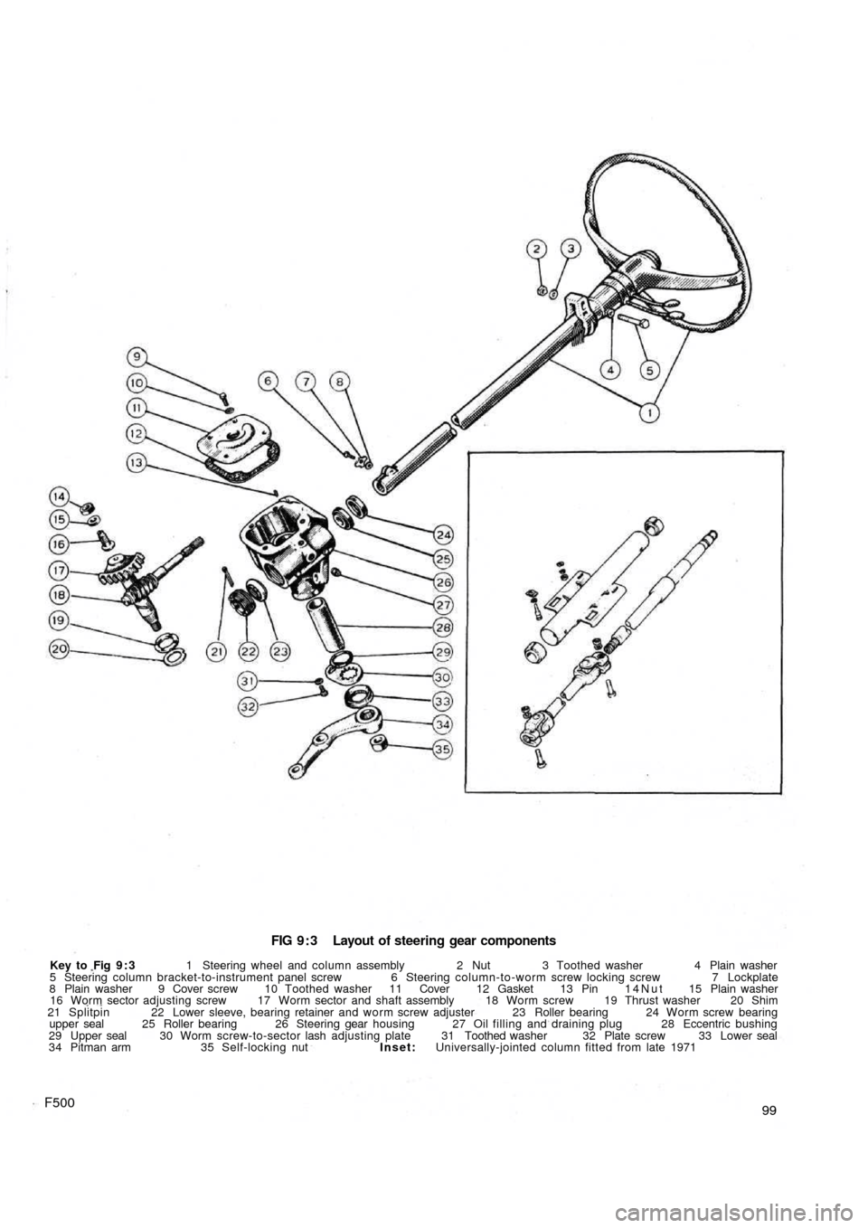
FIG 9 : 3 Layout of steering gear components
Key to Fig 9 : 3 1 Steering wheel and column assembly 2 Nut 3 Toothed washer 4 Plain washer
5 Steering column bracket-to-instrument panel screw 6 Steering column-to-worm screw locking screw 7 Lockplate
8 Plain washer 9 Cover screw 10 Toothed washer 11 Cover 12 Gasket 13 Pin 14Nut 15 Plain washer
16 Worm sector adjusting screw 17 Worm sector and shaft assembly 18 Worm screw 19 Thrust washer 20 Shim
21 Splitpin 22 Lower sleeve, bearing retainer and worm screw adjuster 23 Roller bearing 24 Worm screw bearing
upper seal 25 Roller bearing 26 Steering gear housing 27 Oil filling and draining plug 28 Eccentric bushing
29 Upper seal 30 Worm screw-to-sector lash adjusting plate 31 Toothed washer 32 Plate screw 33 Lower seal
34 Pitman arm 35 Self-locking nut Inset: Universally-jointed column fitted from late 1971
99F500
Page 93 of 128
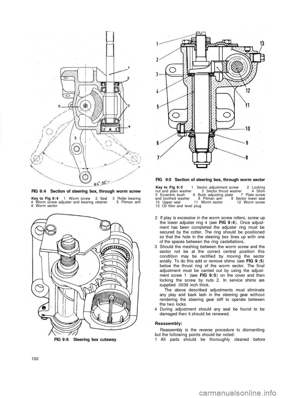
FIG 9 : 4 Section of steering box, through worm screw
Key to Fig 9 : 4 1 Worm screw 2 Seal 3 Roller bearing
4 Worm screw adjuster and bearing retainer 5 Pitman arm
6 Worm sector
FIG 9 : 6 Steering box cutaway
100FIG 9:5 Section of steering box, through worm sector
Key to Fig 9 : 5 1 Sector adjustment screw 2 Locking
nut and plain washer 3 Sector thrust washer 4 Shim
5 Eccentric bush 6 Bush adjusting plate 7 Plate screw
and toothed washer 8 Pitman arm 9 Sector lower seal
10 Upper seal 11 Worm sector 12 Worm screw
13 Oil filler and level plug
2 If play is excessive in the worm screw rollers, screw up
the lower adjuster ring 4 (see FIG 9 : 4) . Once adjust-
ment has been completed the adjuster ring must be
secured by the cotter. The ring should be positioned
so that the hole in the steering box lines up w i t h one
of the spaces between the ring castellations.
3 Should the meshing between the worm screw and the
sector not be at the correct central position this
condition may be rectified by moving the sector
axially. To do this add or remove shims (see FIG 9 :5)
below the thrust ring of the worm sector. The final
adjustment must be carried out by using the adjust-
ment screw 1 (see FIG 9 : 5) on the cover and then
locking the screw by nuts 2. In service shims are
supplied .0039 inch thick.
The above described adjustments must eliminate
any play and back lash in the steering gear without
rendering the steering gear stiff to operate between
the t w o locks.
4 During adjustment should any seal be found to be
damaged then it should be renewed.
Reassembly:
Reassembly is the reverse procedure to dismantling
but the following points should be noted:
1 All parts should be thoroughly cleaned before