Esp 500 FIAT 500 1958 1.G Workshop Manual
[x] Cancel search | Manufacturer: FIAT, Model Year: 1958, Model line: 500, Model: FIAT 500 1958 1.GPages: 128, PDF Size: 9.01 MB
Page 13 of 128
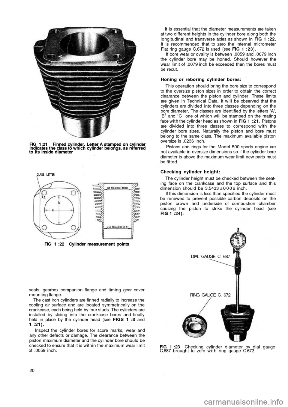
FIG 1:21 Finned cylinder. Letter A stamped on cylinder
indicates the class to which cylinder belongs, as referred
to its inside diameter
CLASS LETTER
FIG 1 :22 Cylinder measurement points
seats, gearbox companion flange and timing gear cover
mounting flange.
The cast iron cylinders are finned radially to increase the
cooling air surface and are located symmetrically on the
crankcase, each being held by four studs. The cylinders are
installed by sliding into the crankcase bores and finally
held in place by the cylinder head (see FIGS 1 :8 and
1 :21).
Inspect the cylinder bores for score marks, wear and
any other defects or damage. The clearance between the
piston maximum diameter and the cylinder bore should be
checked to ensure that it is within the maximum wear limit
of .0059 inch.
20FIG 1 :23 Checking cylinder diameter by dial gauge
C.687 brought to zero w i t h ring gauge C.672 DIAL GAUGE C 687
RING GAUGE C. 672 The cylinder height must be checked between the seat-
ing face on the crankcase and the top surface and this
dimension should be 3.5433 ±0006 inch.
If this dimension is less than specified the cylinder must
be renewed to prevent possible carbon deposits on the
piston crown and underside of combustion chamber
causing the piston to strike the cylinder head (see
FIG 1 :24). Checking cylinder height: This operation should bring the bore size to correspond
to the oversize piston sizes in order to obtain the correct
clearance between the piston and cylinder. These
limits
are given in Technical Data. It will be observed that the
cylinders are divided into three classes depending on the
bore diameter. The classes are identified by the letters 'A',
'B
1 and ' C , one of which will be stamped on the mating
face with the cylinder head as shown in FIG 1 :21. Pistons
are divided into three classes to correspond with the
cylinder bore sizes. Naturally the piston and bore must
belong to the same class. The maximum available piston
oversize is .0236 inch.
Pistons and rings for the Model 500 sports engine are
not available in oversize dimensions so if the cylinder bore
diameter is above the maximum wear limit new parts must
be fitted.Honing or reboring cylinder bores: It is essential that the diameter measurements are taken
at t w o different heights in the cylinder bore along both the
longitudinal and transverse axles as shown in FIG 1 :22.
It is recommended that to zero the internal micrometer
Fiat ring gauge C.672 is used (see FIG 1 :23).
If bore wear or ovality is between .0059 and .0079 inch
the cylinder bore may be honed. Should however the
wear limit of .0079 inch be exceeded then the bores must
be recut.
Page 14 of 128
Insert a .0079 ± .00197 inch thick oil paper gasket
between the crankcase and cylinder bottom face and a
.0236 to .0275 inch thick graphitized asbestos gasket
between the cylinder and cylinder head. The compression
of the gaskets on assembly will eliminate any very small
differences between the t w o mating surfaces.
Inspection of tappet seats:
The tappet seats should be checked for scoring and
correct clearance which must not exceed .00315 inch.
Should the clearance be greater than the maximum
specified the seating may be reamed to oversize dimen-
sions as detailed in Technical Data. Tappets are avail-
able in .00197 and .00394 inch diameter oversize.
1 :9 Piston assembly
Inspection:
Before inspection the pistons must be thoroughly
cleaned and the ring grooves and piston head decarbo-
nized. Check for deep score marks and signs of distortion
or fracture especially around the skirt and piston pin areas.
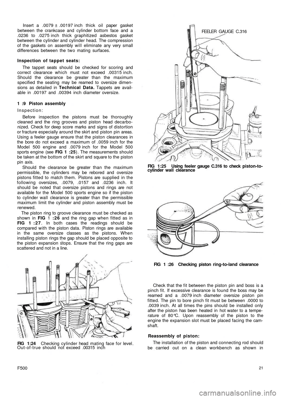
Using a feeler gauge ensure that the piston clearances in
the bore do not exceed a maximum of .0059 inch for the
Model 500 engine and .0079 inch for the Model 500
sports engine (see FIG 1 :25) . The measurements should
be taken at the bottom of the skirt and square to the piston
pin axis.
Should the clearance be greater than the maximum
permissible, the cylinders may be rebored and oversize
pistons fitted to m
atch them. Pistons are supplied in the
following oversizes, .0079, .0157 and .0236 inch. It
should be noted that oversize pistons and rings are not
available for the Model 500 sports engine so if the piston
to cylinder wall clearance is greater than the permissible
maximum limit the cylinder and piston assembly must be
renewed.
The piston ring to groove clearance must be checked as
shown in FIG 1 :26 and the ring gap when fitted as in
FIG 1 : 2 7. In both cases the readings should be
compared with the piston data. Piston rings are available
in the same oversize classes as the pistons. When
installing piston rings the gap should be placed opposite to
the piston expansion stops. Ensure that the ring gaps are
scattered and not in a line.
FIG 1:24 Checking cylinder head mating face f o r level
Out-of-true should not exceed .00315 i n c h
F50021
The installation of the piston and connecting rod should
be carried out on a clean workbench as shown in Reassembly of piston: Check that the f i t between the piston pin and boss is a
pinch fit. If excessive clearance is found the boss may be
reamed and a .0079 inch diameter oversize piston pin
fitted. The pin to bore pinch fit must be between .0000 to
.0039 inch. At all times the pins should be installed only
after the piston has been heated in hot water to a tempe-
rature of 80°C. Upon reassembly of the piston to the
engine the expansion slot must be placed facing the cam-
shaft.FIG 1 :26 Checking piston ring-to-land clearance FEELER GAUGE C.316
FIG 1:25 Using feeler gauge C.316 to check piston-to-
cylinder wall clearance
Page 16 of 128
tolerance range of .00043 to .00240 inch or less than
.0059 inch the bearing inserts may be used again with-
out any need for regrinding. Should however the
clearance be greater than .0059 inch the inserts must be
renewed, using undersize inserts if the crankpin journals
have been reground.
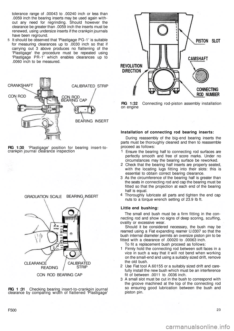
It should be observed that 'Plastigage PG-1' is suitable
for measuring clearances up to .0030 inch so that if
carrying out 3 above produces no flattening of the
'Plastigage' the procedure must be repeated using
'Plastigage PR-1' which enables clearances up to
.0060 inch to be measured.
5
CRANKSHAFT
CON RODCALIBRATED STRIP
CON ROD
BEARING CAP
BEARING INSERT
FIG 1:30 'Plastigage' position for bearing insert-to-
crankpin journal clearance inspection
GRADUATION SCALE
BEARING .INSERT
CLEARANCE
READINGCALIBRATED
STRIP
CON ROD BEARING CAP
FIG 1 :31 Checking bearing insert-to-crankpin journal
clearance by comparing width of flattened 'Plastigage'
F50023
To fit a replacement bush proceed as follows:
Firmly hold the connecting rod between soft faces in a
vice in such a way that it will not bend when working
on the small-end and using a suitably sized drift, remove
the old bush.
Use Fiat tool A.60155 or a suitably sized drift and care-
fully install the new bush which must be an interference
fit of between .0011 to .0036 inch.
A small slot must be cut in the bush to correspond w i t h
the groove machined at the top of the connecting rod
so ensuring good lubrication between the bush and
piston pin. 1
2
3The small end bush must be a firm fitting in the con-
necting rod and show no signs of deep scoring, scuffing,
ovality or excessive wear.
Should it be considered necessary, the bush may be
reamed using a Fiat expanding reamer U.0307 so that the
bush internal diameter permits an oversize piston pin to be
fitted with a clearance of .00020 to .00063 inch. Little end bushing:Installation of connecting rod bearing inserts:
During reassembly of the big-end bearing inserts the
parts must be thoroughly cleaned and then to reassemble
proceed as follows:
Ensure the bearing half to connecting rod surfaces are
perfectly smooth and free of score marks. Under no
circumstances may the bearing surface be reworked.
Check that the bearing half inserts are properly seated,
with the locating lugs fitting into their slots: this is
essential to obtain
correct bearing clearance.
As the circumference of the bearing half is greater than
the seats in connecting rod and cap the bearing must be
fitted so that the projection at each end of the bearing
half is equal.
Thoroughly lubricate all parts and tighten the end cap
nuts to a torque wrench setting of 23.9 Ib ft. 1
2
3
4FIG 1:32 Connecting rod-piston assembly installation
on engine
REVOLUTION
DIRECTIONPISTON SLOT
CAMSHAFT
CONNECTING
ROD NUMBER
Page 32 of 128
3 Engine warm-up:
As the engine begins to warm up to its normal operating
temperature, gradually push home the starting device
lever so as only to supply the engine with the richened
charge enabling the cold engine operation to be smooth
and regular. Position ' B ' (FIG 2:6).
4 Normal car driving:
Once the engine has reached its normal operating
temperature the starting device should be completely
brought out of operation by bringing the control lever to
the position 'C (FIG 2:6).
Idle speed adjustment:
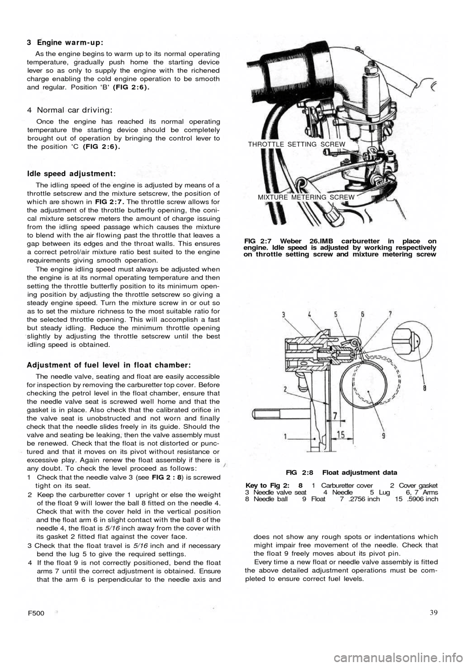
The idling speed of the engine is adjusted by means of a
throttle setscrew and the mixture setscrew, the position of
which are shown in FIG 2:7. The throttle screw allows for
the adjustment of the throttle butterfly opening, the coni-
cal mixture setscrew meters the amount of charge issuing
from the idling speed passage which causes the mixture
to blend with the air flowing past the throttle that leaves a
gap between its edges and the throat walls. This ensures
a correct petrol/air mixture ratio best suited to the engine
requirements giving smooth operation.
The engine idling speed must always be adjusted when
the engine is at its normal operating temperature and then
setting the throttle butterfly position to its minimum open-
ing position by adjusting the throttle setscrew so giving a
steady engine speed. Turn the mixture screw in or out so
as to set the mixture richness to the most suitable ratio for
the selected throttle opening. This will accomplish a fast
but steady idling. Reduce the minimum throttle opening
slightly by adjusting the throttle setscrew until the best
idling speed is obtained.
Adjustment of fuel level in float chamber:
The needle valve, seating and float are easily accessible
for inspection by removing the carburetter top cover. Before
checking the petrol level in the float chamber, ensure that
the needle valve seat is screwed well home and that the
gasket is in place. Also check that the calibrated orifice in
the valve seat is unobstructed and not worn and finally
check that the needle slides freely in its guide. Should the
valve and seating be leaking, then the valve assembly must
be renewed. Check that the float is not distorted or punc-
tured and that it moves on its pivot without resistance or
excessive play. Again renew the float assembly if there is
any doubt. To check the level proceed as follows:
1 Check that the needle valve 3 (see FIG 2 : 8) is screwed
tight on its seat.
2 Keep the carburetter cover 1 upright or else the weight
of the float 9 will lower the ball 8 fitted on the needle 4.
Check that with the cover held in the vertical position
and the float arm 6 in slight contact with the ball 8 of the
needle 4, the float is 5/16 inch away from the cover with
its gasket 2
fitted flat against the cover face.
3 Check that the float travel is 5/16 inch and if necessary
bend the lug 5 to give the required settings.
4 If the float 9 is not correctly positioned, bend the float
arms 7 until the correct adjustment is obtained. Ensure
that the arm 6 is perpendicular to the needle axis and
F50039
does not show any rough spots or indentations which
might impair free movement of the needle. Check that
the float 9 freely moves about its pivot pin.
Every time a new float or needle valve assembly is fitted
the above detailed adjustment operations must be com-
pleted to ensure correct fuel levels. FIG 2 : 8 Float adjustment data
Key to Fig 2: 8 1 Carburetter cover 2 Cover gasket
3 Needle valve seat 4 Needle 5 Lug 6, 7 Arms
8 Needle ball 9 Float 7 .2756 inch 15 .5906 inch FIG 2 : 7 Weber 26.IMB carburetter in place on
engine. Idle speed is adjusted by working respectively
on throttle setting screw and mixture metering screw
THROTTLE SETTING SCREW
MIXTURE METERING SCREW
Page 38 of 128
Air cleaner—station wagon:
A pleated paper air cleaner element is housed in a
special air intake chamber connected to the front of the
engine air cooling cowling (see FIG 4 : 2) . This chamber
will be seen located towards the rear of t h e power unit
compartment. Remove the retaining wing nut, lift off the
lid and the element can be withdrawn by lifting upwards.
2:10 Blow-by-gases recirculation device
Engine 110 F.000
All the oil vapours and blow-by-gases that are formed
in the engine crankcase are drawn to the cylinder head
cover recess 1 (see FIG 2:18). From here they travel into
the pipe 5 via a breather valve 2 which is firmly attached to
the oil filler cap 3 and the strainer 4 located in the filler
neck. The oil vapours and gases are then d r a w n back into
the duct 9 from the pipe 5 which connects the air cleaner
6 to the carburetter 7. This ensures a complete closed cir-
cuit circulation.
Engine 120.000:
From engine No. 288156 the oil vapours and blow-by-
gases instead of being exhausted to the atmosphere are
conveyed to the air cleaner and from here they are drawn
back into the combustion chambers. To ensure that an
excessive of oil vapour does not pass along the piping
with the blow-by-gases a diaphragm is fitted in the duct
in front of the breather valve 2 (see FIG 2 :18), the dia-
phragm comprising a filter gauze 11 and moveable parti-
tion 10.
It should be noted that the oil vapour strainer 4 (see
FIG 2:18) and the flame trap 8 can easily be removed
from their seating for cleaning or renewal.
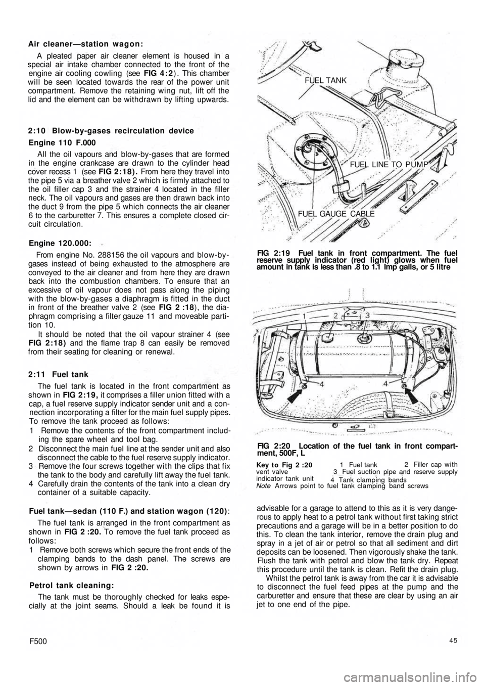
2 : 1 1 Fuel tank
The fuel tank is located in the front compartment as
shown in FIG 2:19, it comprises a filler union fitted with a
cap, a fuel reserve supply indicator sender unit and a con-
nection incorporating a filter for the main fuel supply pipes.
To remove the tank proceed as follows:
1 Remove the contents of the front compartment includ-
ing the spare wheel and tool bag.
2 Disconnect the main fuel line at the sender unit and also
disconnect the cable to the fuel reserve supply indicator.
3 Remove the four screws together w i t h the clips that fix
the tank to the body and carefully lift away the fuel tank.
4 Carefully drain the contents of the tank into a clean dry
container of a suitable capacity.
Fuel tank—sedan (110 F.) and station wagon (120):
The fuel tank is arranged in the front compartment as
shown in FIG 2 :20. To remove the fuel tank proceed as
follows:
1 Remove both screws which secure the front ends of the
clamping bands to the dash panel. The screws are
shown by arrows in FIG 2 :20.
Petrol tank cleaning:
The tank must be thoroughly checked for leaks espe-
cially at the joint seams. Should a leak be found it is
F50045
advisable for a garage to attend to this as it is very dange-
rous to apply heat to a petrol tank without first taking strict
precautions and a garage will be in a better position to do
this. To clean the tank interior, remove the drain plug and
spray in a jet of air or petrol so that all sediment and dirt
deposits can be loosened. Then vigorously shake the tank.
Flush the tank w i t h petrol and blow the tank dry. Repeat
this procedure until the tank is clean. Refit the drain plug.
Whilst the petrol tank is away from the car it is advisable
to disconnect the fuel feed pipes at the pump and the
carburetter and ensure that these are clear by using an air
jet to one end of the pipe.
Key t o Fig 2 :20
Note Arrows point to fuel tank clamping band screws vent valve
indicator tank unit1 Fuel tank2 Filler cap with
3 Fuel suction pipe and reserve supply
4 Tank clamping bands
FIG 2:20 Location of the fuel tank in front compart-
ment, 500F, L FIG 2:19 Fuel tank in front compartment. The fuel
reserve supply indicator (red light) glows when fuel
amount in tank is less than .8 to 1.1 Imp galls, or 5 litre FUEL TANK
FUEL LINE TO PUMP
FUEL GAUGE CABLE
Page 43 of 128
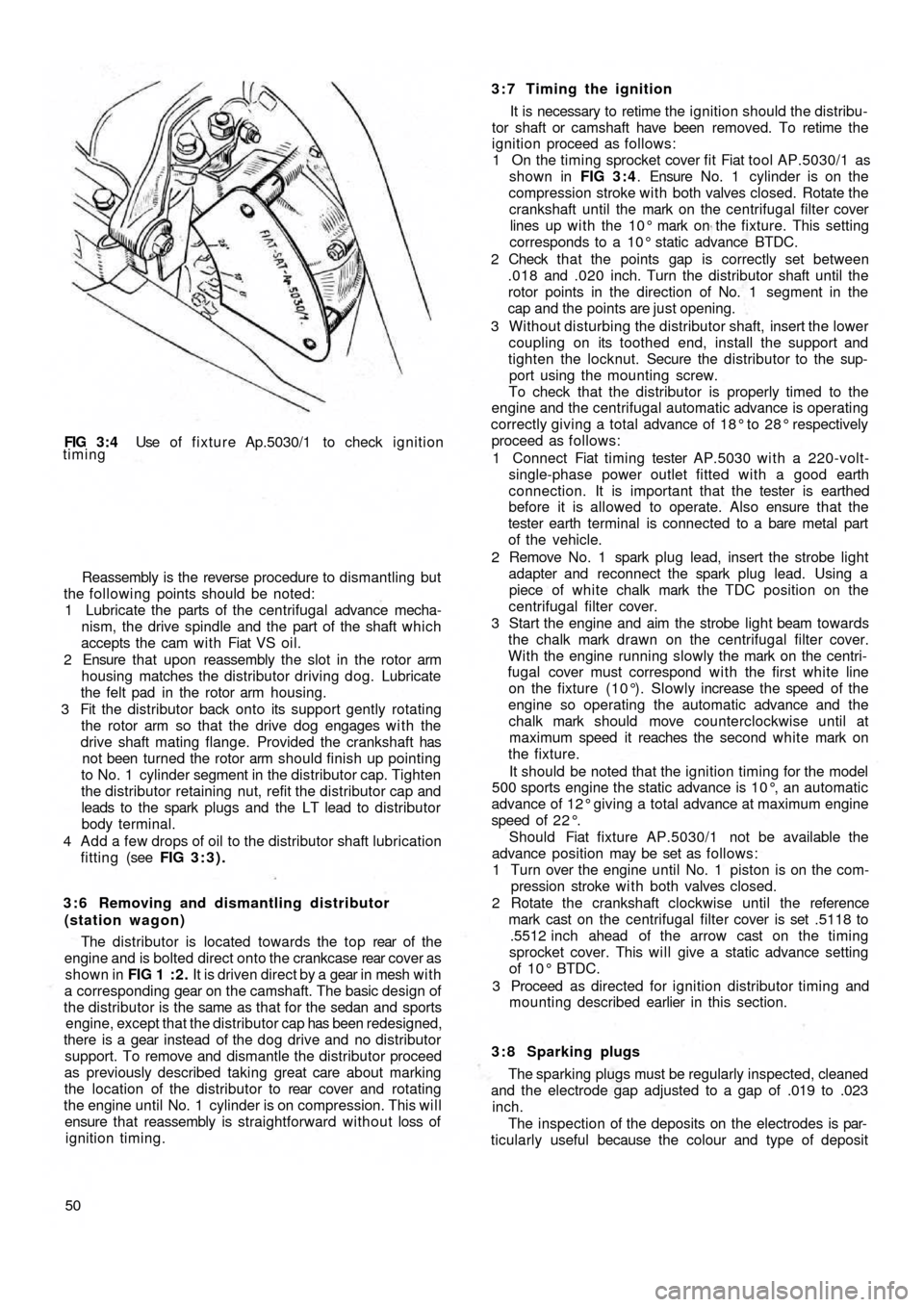
FIG 3 : 4 Use of fixture Ap.5030/1 to check ignition
timing
Reassembly is the reverse procedure to dismantling but
the following points should be noted:
1 Lubricate the parts of the centrifugal advance mecha-
nism, the drive spindle and the part of the shaft which
accepts the cam w i t h Fiat VS oil.
2 Ensure that upon reassembly the slot in the rotor arm
housing matches the distributor driving dog. Lubricate
the felt pad in the rotor arm housing.
3 Fit the distributor back onto its support gently rotating
the rotor arm so that the drive dog engages w i t h the
drive shaft mating flange. Provided the crankshaft has
not been turned the rotor arm should finish up pointing
to No. 1 cylinder segment in the distributor cap. Tighten
the distributor retaining nut, refit the distributor cap and
leads to the spark plugs and the LT lead to distributor
body terminal.
4 Add a few drops of oil to the distributor shaft lubrication
fitting (see FIG 3:3).
3 : 6 Removing and dismantling distributor
(station wagon)
The distributor is located towards the top rear of t h e
engine and is bolted direct onto the crankcase rear cover as
shown in FIG 1 : 2 . It is driven direct by a gear in mesh w i t h
a corresponding gear on the camshaft. The basic design of
the distributor is the same as that for the sedan and sports
engine, except that the distributor cap has been redesigned,
there is a gear instead of the dog
drive and no distributor
support. To remove and dismantle the distributor proceed
as previously described taking great care about marking
the location of the distributor to rear cover and rotating
the engine until No. 1 cylinder is on compression. This will
ensure that reassembly is straightforward without loss of
ignition timing.
503:7 Timing the ignition
It is necessary to retime the ignition should the distribu-
tor shaft or camshaft have been removed. To retime the
ignition proceed as follows:
1 On the timing sprocket cover fit Fiat tool AP.5030/1 as
shown in FIG 3 : 4. Ensure No. 1 cylinder is on the
compression stroke with both valves closed. Rotate the
crankshaft until the mark on the centrifugal filter cover
lines up w i t h the 10° mark on the fixture. This setting
corresponds to a 10° static advance BTDC.
2 Check t h a t the points gap is correctly set between
.018 and .020 inch. Turn the distributor shaft until the
rotor points in the direction of No. 1 segment in the
cap and the points are just opening.
3 Without disturbing the distributor shaft, insert the lower
coupling on its toothed end, install the support and
tighten the locknut. Secure the distributor to the sup-
port using the mounting screw.
To check that the distributor is properly timed to the
engine and the centrifugal automatic advance is operating
correctly giving a
total advance of 18° to 28° respectively
proceed as follows:
1 Connect Fiat timing tester AP.5030 with a 220-volt-
single-phase power outlet fitted with a good earth
connection. It is important that the tester is earthed
before it is allowed to operate. Also ensure that the
tester earth terminal is connected to a bare metal part
of the vehicle.
2 Remove No. 1 spark plug lead, insert the strobe light
adapter and reconnect the spark plug lead. Using a
piece of white chalk mark the TDC position on the
centrifugal filter cover.
3 Start the engine and aim the strobe light beam towards
the chalk mark drawn on the centrifugal filter cover.
With the engine running slowly the mark on the centri-
fugal cover must correspond wi th the first white line
on the fixture (10°). Slowly increase the speed of the
engine so operating the automatic advance and the
chalk mark should move counterclockwise until at
maximum speed it reaches the second white mark on
the fixture.
It should be noted that the ignition timing for the model
500 sports engine the static advance is 10°, an automatic
advance of 12° giving a total advance at maximum engine
speed of 2 2 ° .
Should Fiat fixture AP.5030/1 not be available the
advance position may be set as follows:
1 Turn over the
engine until No. 1 piston is on the com-
pression stroke w i t h both valves closed.
2 Rotate the crankshaft clockwise until the reference
mark cast on the centrifugal filter cover is set .5118 to
.5512 inch ahead of the arrow cast on the timing
sprocket cover. This will give a static advance setting
of 10° BTDC.
3 Proceed as directed for ignition distributor timing and
mounting described earlier in this section.
3 : 8 Sparking plugs
The sparking plugs must be regularly inspected, cleaned
and the electrode gap adjusted to a gap of .019 to .023
inch.
The inspection of the deposits on the electrodes is par-
ticularly useful because the colour and type of deposit
Page 53 of 128
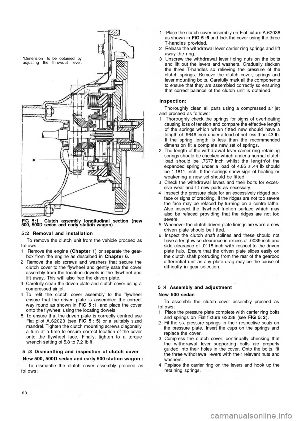
*Dimension to be obtained by
adjusting the throwout lever.
FIG 5:1 Clutch assembly longitudinal section (new
500, 500D sedan and early station wagon)
5 : 2 Removal and installation
To remove the clutch unit from the vehicle proceed as
follows:
1 Remove the engine (Chapter 1) or separate the gear-
box from the engine as described in Chapter 6.
2 Remove the six screws and washers that secure the
clutch cover to the flywheel and gently ease the cover
assembly from the location dowels in the flywheel and
lift away. This will also free the driven plate.
3 Carefully clean the driven plate and clutch cover using a
compressed air jet.
4 To refit the clutch cover assembly to the flywheel
ensure that the driven plate is assembled the correct
way round as shown in FIG 5 :1 and place the cover
onto the flywheel using the locating dowels.
5 To ensure that the driven plate is correctly centred use
Fiat pilot A.62023 (see FIG 5 : 5) or a suitably sized
mandrel. Tighten the clutch mounting screws diagonally
a turn at a time to ensure correct location of the cover
onto the flywheel face. Finally, tighten to a torque
wrench setting of 5.8 to 7.2 Ib ft.
5 :3 Dismantling and inspection of clutch cover
New 500, 500D sedan and early 500 station wagon :
To dismantle the clutch cover assembly proceed as
follows:
60
To assemble the clutch cover assembly proceed as
follows:
1 Place the pressure plate complete with carrier ring bolts
and springs on Fiat fixture 62038 (see FIG 5 : 2).
2 Fit the six pressure springs in their respective seats on
the pressure plate. Insert the cups on the springs and
replace the cover.
3 Compress the clutch cover, continually checking that
the withdrawal lever supporting bolts are properly
guided into their holes in the cover. Onto the bolts, fit
the three withdrawal levers w i t h their relevant nuts and
washers.
4 Replace the carrier ring on the levers and hook up the
retaining springs. 5 :4 Assembly and adjustment
N e w 500 sedan1 Place the clutch cover assembly on Fiat fixture A.62038
as shown in FIG 5 :6 and lock the cover using the three
T-handles provided.
2 Release the w i thdrawal lever carrier ring springs and lift
away the ring.
3 Unscrew the withdrawal lever fixing nuts on the bolts
and lift out the levers and washers. Gradually slacken
the three T-handles so relieving the pressure of the
clutch springs. Remove the clutch cover, springs and
lever mounting bolts. Carefully mark all the components
to ensure that they are assembled correctly so ensuring
that correct balance of the clutch unit is obtained.
Inspection:
Thoroughly clean all parts using a compressed air jet
and proceed as follows:
1 Thoroughly check the springs for signs of overheating
causing loss of tension and compare the effective length
of the springs which when fitted new should have a
length of .9646 inch under a load of not less than 43 Ib.
If the spring length is less t h a n t h e recommended
dimension fit a complete new set of springs.
2 The length of the withdrawal lever carrier ring retaining
springs should be checked which under a normal clutch
load should be .7677 inch whilst the length'of the
expanded spring under a load of 4.85 ± .44 Ib should
be 1.1811 inch. If the springs show sign of heating or
weakening a new set should be fitted.
3 Check the withdrawa l levers and their bolts for exces-
sive wear and fit new parts as necessary.
4 Inspect the pressure plate for an excessively ridged sur-
face or signs of cracking. If the ridges are not too severe
the face may be refaced by turning on a centre lathe.
Also inspect the flywheel friction surface which may
also be refaced providing that the ridges are not too
severe.
5 Whenever the clutch driven plate linings are worn a new
driven plate should be fitted.
6 Inspect the clutch shaft splines and these should not
have a lengthwise clearance in excess of .0039 inch and
side clearance of .0118 inch w i t h respect to the driven
plate hub. Ensure that the driven plate slides easily on
the clutch shaft protruding from the rear of the gearbox
differential unit as any plate drag may be the cause of
d i f f i c u l t y in gear selection.
Page 57 of 128
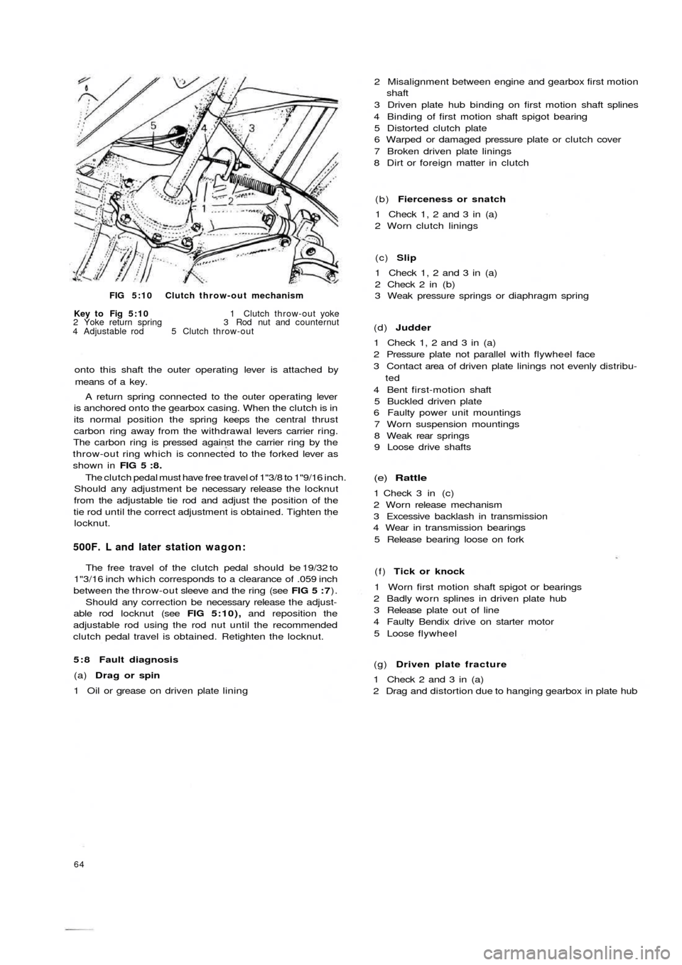
FIG 5:10 Clutch throw-out mechanism
Key to Fig 5:10 1 Clutch throw-out yoke
2 Yoke return spring 3 Rod nut and counternut
4 Adjustable rod 5 Clutch throw-out
onto this shaft the outer operating lever is attached by
means of a key.
A return spring connected to the outer operating lever
is anchored onto the gearbox casing. When the clutch is in
its normal position the spring keeps the central thrust
carbon ring away from the withdrawal levers carrier ring.
The carbon ring is pressed against the carrier ring by the
throw-out ring which is connected to the forked lever as
shown in FIG 5 : 8 .
The clutch pedal must have free travel of 1"3/8 to 1"9/16 inch.
Should any adjustment be necessary release the locknut
from the adjustable tie rod and adjust the position of the
tie rod until the correct adjustment is obtained. Tighten the
locknut.
500F. L and later station wagon:
The free travel of the clutch pedal should be 19/32 to
1"3/16 inch which corresponds to a clearance of .059 inch
between the throw-out sleeve and the ring (see FIG 5 : 7).
Should any correction be necessary release the adjust-
able rod locknut (see FIG 5:10), and reposition the
adjustable rod using the rod nut until the recommended
clutch pedal travel is obtained. Retighten the locknut.
5 : 8 Fault diagnosis
(a) Drag or spin
1 Oil or grease on driven plate lining
64
(g) Driven plate fracture
1 Check 2 and 3 in (a)
2 Drag and distortion due to hanging gearbox in plate hub (f) Tick or knock
1 Worn first motion shaft spigot or bearings
2 Badly worn splines in driven plate hub
3 Release plate out of line
4 Faulty Bendix drive on starter motor
5 Loose flywheel
(e) Rattle
1 Check 3 in (c)
2 Worn release mechanism
3 Excessive backlash in transmission
4 Wear in transmission bearings
5 Release bearing loose on fork (d) Judder
1 Check 1, 2 and 3 in (a)
2 Pressure plate not parallel with flywheel face
3 Contact area of driven plate linings not evenly distribu-
ted
4 Bent first-motion shaft
5 Buckled driven plate
6 Faulty power unit mountings
7 Worn suspension mountings
8 Weak rear springs
9 Loose drive shafts (c) Slip
1 Check 1, 2 and 3 in (a)
2 Check 2 in (b)
3 Weak pressure springs or diaphragm spring (b) Fierceness or snatch
1 Check 1, 2 and 3 in (a)
2 Worn clutch linings 2 Misalignment between engine and gearbox first motion
shaft
3 Driven plate hub binding on first motion shaft splines
4 Binding of first motion shaft spigot bearing
5 Distorted clutch plate
6 Warped or damaged pressure plate or clutch cover
7 Broken driven plate linings
8 Dirt or foreign matter in clutch
Page 76 of 128
high bearing preload. To reset remove the wheel shaft
and fit a new resilient spacer. Repeat the rotation
torque test.
Swinging arm adjustment:
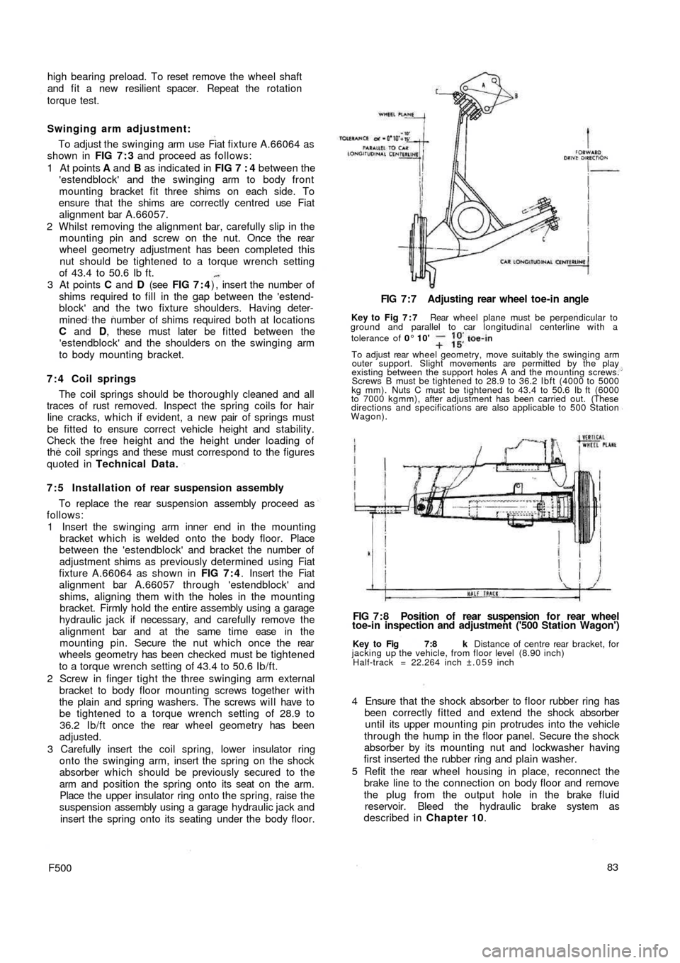
To adjust the swinging arm use Fiat fixture A.66064 as
shown in FIG 7 : 3 and proceed as follows:
1 At points A and B as indicated in FIG 7 : 4 between the
'estendblock' and the swinging arm to body front
mounting bracket fit three shims on each side. To
ensure that the shims are correctly centred use Fiat
alignment bar A.66057.
2 Whilst removing the alignment bar, carefully slip in the
mounting pin and screw on the nut. Once the rear
wheel geometry adjustment has been completed this
nut should be tightened to a torque wrench setting
of 43.4 to 50.6 Ib ft.
3 At points C and D (see FIG 7 : 4) , insert the number of
shims required to fill in the gap between the 'estend-
block' and the two fixture shoulders. Having deter-
mined the number of shims required both at locations
C and D, these must later be fitted between the
'estendblock' and the shoulders on the swinging arm
to body mounting bracket.
7 : 4 Coil springs
The coil springs should be thoroughly cleaned and all
traces of rust removed. Inspect the spring coils for hair
line cracks, which if evident, a new pair of springs must
be fitted to ensure correct vehicle height and stability.
Check the free
height and the height under loading of
the coil springs and these must correspond to the figures
quoted in Technical Data.
7:5 Installation of rear suspension assembly
To replace the rear suspension assembly proceed as
follows:
1 Insert the swinging arm inner end in the mounting
bracket which is welded onto the body floor. Place
between the 'estendblock' and bracket the number of
adjustment shims as previously determined using Fiat
fixture A.66064 as shown in FIG 7 : 4. Insert the Fiat
alignment bar A.66057 through 'estendblock' and
shims, aligning them with the holes in the mounting
bracket. Firmly hold the entire assembly using a garage
hydraulic jack if necessary, and carefully remove the
alignment bar and at the same time ease in t h e
mounting pin. Secure the nut which once the rear
wheels geometry has been checked must be tightened
to a torque wrench setting of 43.4 to 50.6 Ib/ft.
2 Screw in finger tight the three swinging arm external
bracket to body floor mounting screws together w i t h
the plain and spring washers. The screws will have to
be tightened to a torque wrench setting of 28.9 to
36.2 Ib/ft once the rear wheel geometry has been
adjusted.
3 Carefully insert the coil spring, lower insulator ring
onto the swinging arm, insert the spring on the shock
absorber which should be previously secured to the
arm and position the spring onto its seat on the arm.
Place the upper insulator ring onto the spring, raise the
suspension assembly using a garage hydraulic jack and
insert the spring onto its seating under the body floor.
F50083 4 Ensure that the shock absorber to floor rubber ring has
been correctly fitted and extend the shock absorber
until its upper mounting pin protrudes into the vehicle
through the hump in the floor panel. Secure the shock
absorber by its mounting nut and lockwasher having
first inserted the rubber ring and plain washer.
5 Refit the rear wheel housing in place, reconnect the
brake line to the connection on body floor and remove
the plug from the output hole in the brake fluid
reservoir. Bleed the hydraulic brake system as
described in Chapter 10.
Key to Fig 7:8 k Distance of centre rear bracket, for
jacking up the vehicle, from floor level (8.90 inch)
Half-track = 22.264 inch ±.059 inch
FIG 7 : 8 Position of rear suspension f o r rear wheel
toe-in inspection and adjustment ('500 Station Wagon') FIG 7 : 7 Adjusting rear wheel toe-in angle
Key to Fig 7 : 7 Rear wheel plane must be perpendicular to
ground and parallel to car longitudinal centerline with a
tolerance of 0° 10'
To adjust rear wheel geometry, move suitably the swinging arm
outer support. Slight movements are permitted by the play
existing between the support holes A and the mounting screws.
Screws B must be tightened to 28.9 to 36.2 Ibft (4000 to 5000
kg mm). Nuts C must be tightened to 43.4 to 50.6 Ib ft (6000
to 7000 kgmm), after adjustment has been carried out. (These
directions and specifications are also applicable to 500 Station
Wagon).
Page 97 of 128
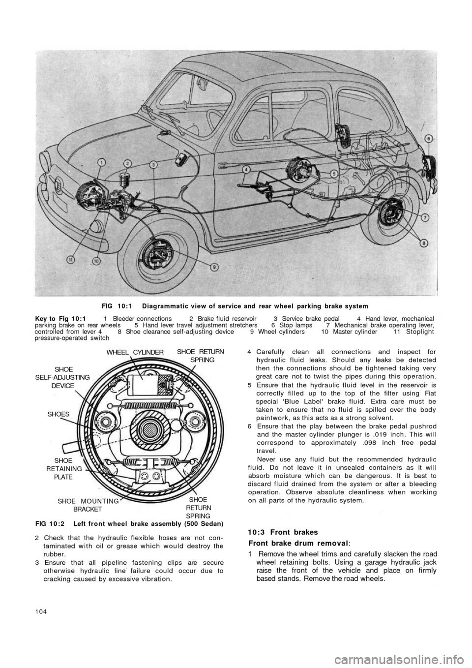
FIG 10:1 Diagrammatic view of service and rear wheel parking brake system
Key to Fig 10:1 1 Bleeder connections 2 Brake fluid reservoir 3 Service brake pedal 4 Hand lever, mechanical
parking brake on rear wheels 5 Hand lever travel adjustment stretchers 6 Stop lamps 7 Mechanical brake operating lever,
controlled from lever 4 8 Shoe clearance self-adjusting device 9 Wheel cylinders 10 Master cylinder 11 Stoplight
pressure-operated switch
FIG 10:2 Left front wheel brake assembly (500 Sedan)
SHOE
RETURN
SPRINGSHOE MOUNTING
BRACKET SHOE
RETAINING
PLATE SHOES
DEVICESHOE
SELF-ADJUSTING
WHEEL CYLINDERSHOE RETURNSPRING
2 Check that the hydraulic flexible hoses are not con-
taminated with oil or grease which would destroy the
rubber.
3 Ensure that all pipeline fastening clips are secure
otherwise hydraulic line failure could occur due to
cracking caused by excessive vibration.
104
4 Carefully clean all connections and inspect for
hydraulic fluid leaks. Should any leaks be detected
then the connections should be tightened taking very
great care not to twist the pipes during this operation.
5 Ensure that the hydraulic fluid level in the reservoir is
correctly filled up to the top of the filter using Fiat
special 'Blue Label' brake fluid. Extra care must be
taken to ensure that no fluid is spilled over the body
paintwork, as this acts as a strong solvent.
6 Ensure that the play between the brake pedal pushrod
and the master cylinder plunger is .019 inch. This will
correspond to approximately .098 inch free pedal
travel.
Never use any fluid but the recommended hydraulic
fluid. Do not leave it in unsealed containers as it will
absorb moisture which can be dangerous. It is best to
discard fluid drained from the system or after a bleeding
operation. Observe absolute cleanliness when working
on all parts of the hydraulic system.
10:3 Front brakes
Front brake drum removal:
1 Remove the wheel trims and carefully slacken the road
wheel retaining bolts. Using a garage hydraulic jack
raise the front of the vehicle and place on firmly
based stands. Remove the road wheels.