key FIAT 500 1959 1.G Owner's Manual
[x] Cancel search | Manufacturer: FIAT, Model Year: 1959, Model line: 500, Model: FIAT 500 1959 1.GPages: 128, PDF Size: 9.01 MB
Page 48 of 128
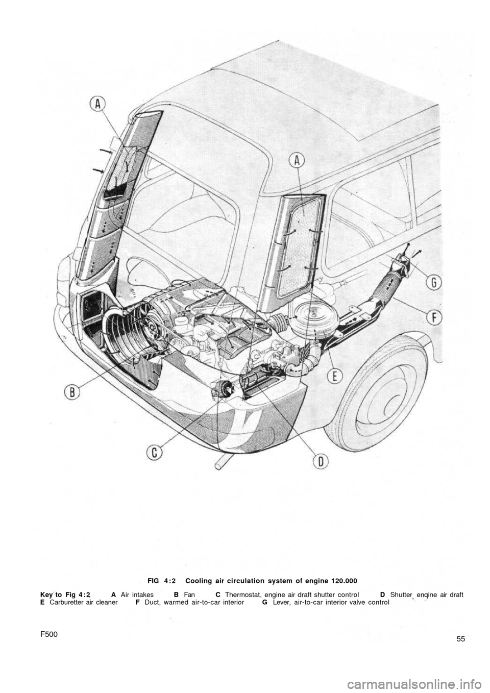
55F500
FIG 4 : 2 Cooling air circulation system of engine 120.000
Key to Fig 4 : 2 A Air intakes B Fan C Thermostat, engine air draft shutter control D Shutter enqine air draft
E Carburetter air cleaner F Duct, warmed air-to-car interior G Lever, air-to-car interior valve control
Page 49 of 128
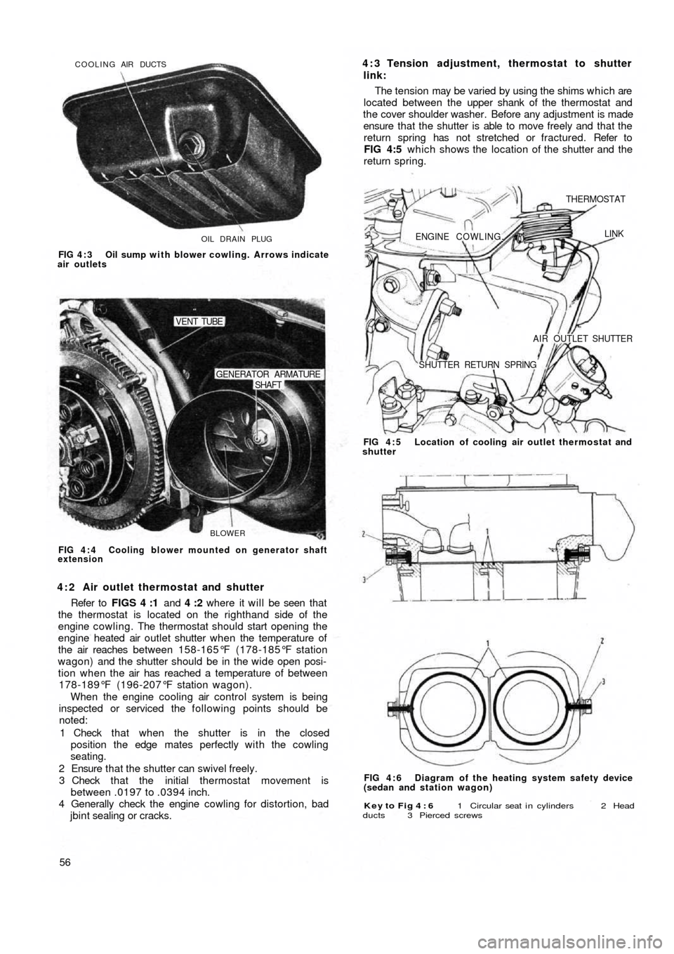
OIL DRAIN PLUG COOLING AIR DUCTS
FIG 4 : 3 Oil sump with blower cowling. Arrows indicate
air outlets
BLOWER
SHAFT GENERATOR ARMATURE
VENT TUBE
FIG 4 : 4 Cooling blower mounted on generator shaft
extension
4 : 2 Air outlet thermostat and shutter
Refer to FIGS 4 :1 and 4 :2 where it will be seen that
the thermostat is located on the righthand side of the
engine cowling. The thermostat should start opening the
engine heated air outlet shutter when the temperature of
the air reaches between 158-165°F (178-185°F station
wagon) and the shutter should be in the wide open posi-
tion when the air has reached a temperature of between
178-189°F (196-207°F station wagon).
When the engine cooling air control system is being
inspected or serviced the following points should be
noted:
1 Check that when the shutter is in the closed
position the edge mates perfectly with the cowling
seating.
2 Ensure that the shutter can swivel freely.
3 Check that the initial thermostat movement is
between .0197 to .0394 inch.
4 Generally check the engine cowling for distortion, bad
jbint sealing or cracks.
56
Key to Fig 4 : 6 1 Circular seat i n cylinders 2 Head
ducts 3 Pierced screws
FIG 4 : 6 Diagram of the heating system safety device
(sedan and station wagon) FIG 4 : 5 Location of cooling air outlet thermostat and
shutter
ENGINE COWLING.
THERMOSTAT
LINK
AIR OUTLET SHUTTER
SHUTTER RETURN SPRING
4 : 3 Tension adjustment, thermostat to shutter
link:
The tension may be varied by using the shims which are
located between the upper shank of the thermostat and
the cover shoulder washer. Before any adjustment is made
ensure that the shutter is able to move freely and that the
return spring has not stretched or fractured. Refer to
FIG 4:5 which shows the location of the shutter and the
return spring.
Page 55 of 128
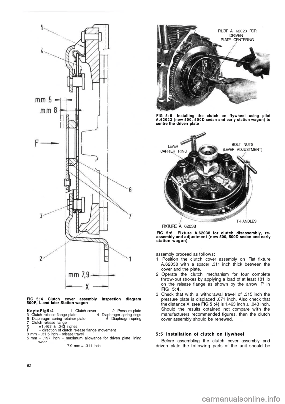
FIG 5 . 4 Clutch cover assembly inspection diagram
500F, L and later Station wagon
KeytoFig5:4 1 Clutch cover 2 Pressure plate
3 Clutch release flange plate 4 Diaphragm spring rings
5 Diaphragm spring retainer plate 6 Diaphragm spring
7 Clutch release flange
X =1.463 ± .043 inches
F = direction of clutch release flange movement
8 mm = .31 5 inch = release travel
5 mm = .197 inch = maximum allowance for driven plate lining
wear7.9 mm = .311 inch
62
5:5 Installation of clutch on flywheel
Before assembling the clutch cover assembly and
driven plate the following parts of the unit should be assembly proceed as follows:
1 Position the clutch cover assembly on Fiat fixture
A.62038 with a spacer .311 inch thick between the
cover and the plate.
2 Operate the clutch mechanism for four complete
throw-out strokes by applying a load of at least 181 Ib
on the release flange as shown by the arrow 'F' in
FIG 5:4.
3 Check that w i t h a withdrawal travel of .315 inch the
pressure plate is displaced .071 inch. Also check that
the distance'X' (see FIG 5 :4) is 1.463 inch ± .043 inch.
Should the results obtained not compare w i t h the
manufacturers recommended figures, then the clutch
cover assembly should be renewed.
FIG 5:6 Fixture A.62038 for clutch disassembly, re-
assembly and adjustment (new 500, 500D sedan and early
station wagon)
FIXTURE A . 62038
T-HANDLES CARRIER RING
LEVERBOLT NUTS
(LEVER ADJUSTMENT) FIG 5 : 5 Installing the clutch on flywheel using pilot
A.62023 (new 500, 500D sedan and early station wagon) to
centre the driven platePILOT A. 62023 FOR
DRIVENPLATE CENTERING
Page 57 of 128
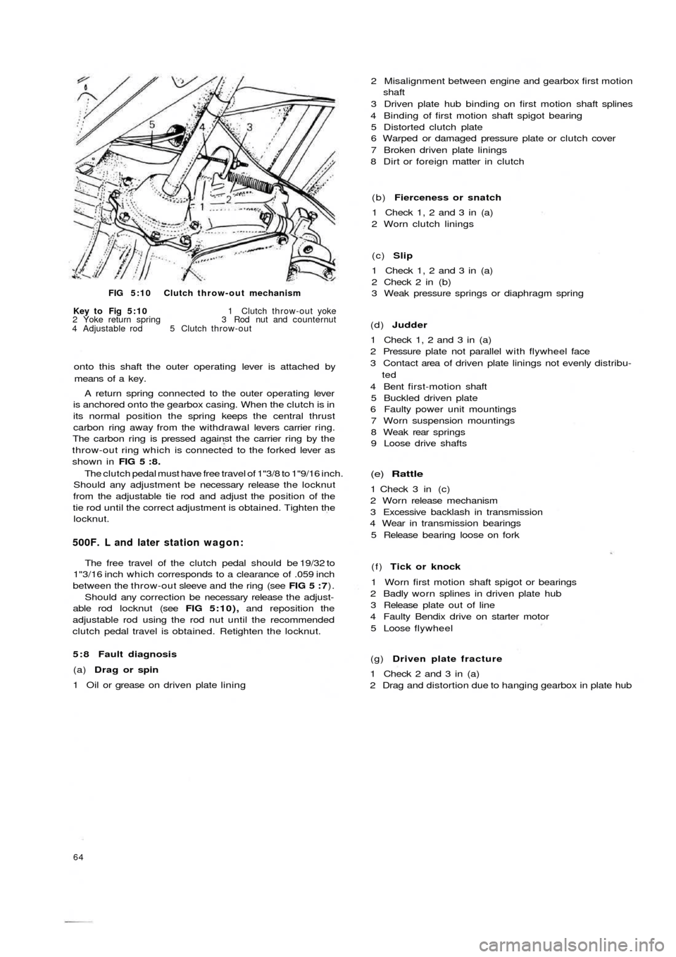
FIG 5:10 Clutch throw-out mechanism
Key to Fig 5:10 1 Clutch throw-out yoke
2 Yoke return spring 3 Rod nut and counternut
4 Adjustable rod 5 Clutch throw-out
onto this shaft the outer operating lever is attached by
means of a key.
A return spring connected to the outer operating lever
is anchored onto the gearbox casing. When the clutch is in
its normal position the spring keeps the central thrust
carbon ring away from the withdrawal levers carrier ring.
The carbon ring is pressed against the carrier ring by the
throw-out ring which is connected to the forked lever as
shown in FIG 5 : 8 .
The clutch pedal must have free travel of 1"3/8 to 1"9/16 inch.
Should any adjustment be necessary release the locknut
from the adjustable tie rod and adjust the position of the
tie rod until the correct adjustment is obtained. Tighten the
locknut.
500F. L and later station wagon:
The free travel of the clutch pedal should be 19/32 to
1"3/16 inch which corresponds to a clearance of .059 inch
between the throw-out sleeve and the ring (see FIG 5 : 7).
Should any correction be necessary release the adjust-
able rod locknut (see FIG 5:10), and reposition the
adjustable rod using the rod nut until the recommended
clutch pedal travel is obtained. Retighten the locknut.
5 : 8 Fault diagnosis
(a) Drag or spin
1 Oil or grease on driven plate lining
64
(g) Driven plate fracture
1 Check 2 and 3 in (a)
2 Drag and distortion due to hanging gearbox in plate hub (f) Tick or knock
1 Worn first motion shaft spigot or bearings
2 Badly worn splines in driven plate hub
3 Release plate out of line
4 Faulty Bendix drive on starter motor
5 Loose flywheel
(e) Rattle
1 Check 3 in (c)
2 Worn release mechanism
3 Excessive backlash in transmission
4 Wear in transmission bearings
5 Release bearing loose on fork (d) Judder
1 Check 1, 2 and 3 in (a)
2 Pressure plate not parallel with flywheel face
3 Contact area of driven plate linings not evenly distribu-
ted
4 Bent first-motion shaft
5 Buckled driven plate
6 Faulty power unit mountings
7 Worn suspension mountings
8 Weak rear springs
9 Loose drive shafts (c) Slip
1 Check 1, 2 and 3 in (a)
2 Check 2 in (b)
3 Weak pressure springs or diaphragm spring (b) Fierceness or snatch
1 Check 1, 2 and 3 in (a)
2 Worn clutch linings 2 Misalignment between engine and gearbox first motion
shaft
3 Driven plate hub binding on first motion shaft splines
4 Binding of first motion shaft spigot bearing
5 Distorted clutch plate
6 Warped or damaged pressure plate or clutch cover
7 Broken driven plate linings
8 Dirt or foreign matter in clutch
Page 60 of 128
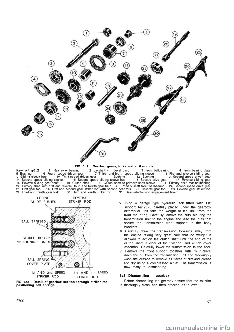
FIG 6 :2 Gearbox gears, forks and striker rods
KeytoFig6:2 1 Rear roller bearing 2 Layshaft with bevel pinion 3 Front ballbearing 4 Front bearing plate
5 Bushing 6 Fourth-speed driven gear 7 Third- and fourth-speed sliding sleeve 8 First and reverse sliding gear
9 Sliding sleeve hub 10 Third-speed driven gear 11 Bushing 12 Bushing 13 Second-speed driven gear
14 Second-speed sliding sleeve 15 Second-speed sliding sleeve hub 16 Speedo drive gear 17 Reverse sliding gear
18 Reverse sliding gear shaft 19 Clutch shaft 20 Clutch shaft-to-primary shaft sleeve 21 Primary shaft rear ballbearing
22 Primary shaft with first and reverse, third and fourth gear train 23 Primary shaft front ballbearing 24 Second-speed drive gear
25 First gear fork 26 First and second gear striker rod with second gear fork 27 Reverse gear fork 28 Reverse gear striker rod
29 Third and fourth gear fork 30 Third and fourth striker rod 31 Gear selector and engagement lever
SPRING
GUIDE BUSHES
REVERSESTRIKER R O D
BALL SPRINGS
POSITIONING BALLS STRIKER R O D
BALL SPRING
COVER PLATE
1st A N D 2 n d SPEED
STRIKER R O D3 r d A N D 4 t h SPEED
STRIKER R O D
FIG 6 : 3 Detail of gearbox section through striker rod
positioning ball springs
F50067 5 Using a garage type hydraulic jack fitted with Fiat
support Arr.2076 carefully placed under the gearbox-
differential unit take the weight of the unit from the
front mounting. Carefully remove the nuts securing the
transmission unit to the engine and also the nuts that
secure the transmission front support to the body
brackets.
6 Carefully draw the transmission forwards away from
the engine taking very great care that no weight is
allowed to act on the clutch shaft until the end of the
clutch shaft is clear of the flywheel and clutch cover
assembly. Carefully lower the transmission to the floor.
7 Remove the front support together with its rubbers,
drain the oil from the transmission unit and thoroughly
wash the outside to remove all traces of dirt and grease
and dry using a compressed air jet. The transmission is
now ready for dismantling.
6:3 Dismantling— gearbox
Before dismantling the gearbox ensure that the exterior
is thoroughly clean and then proceed as follows:
Page 62 of 128
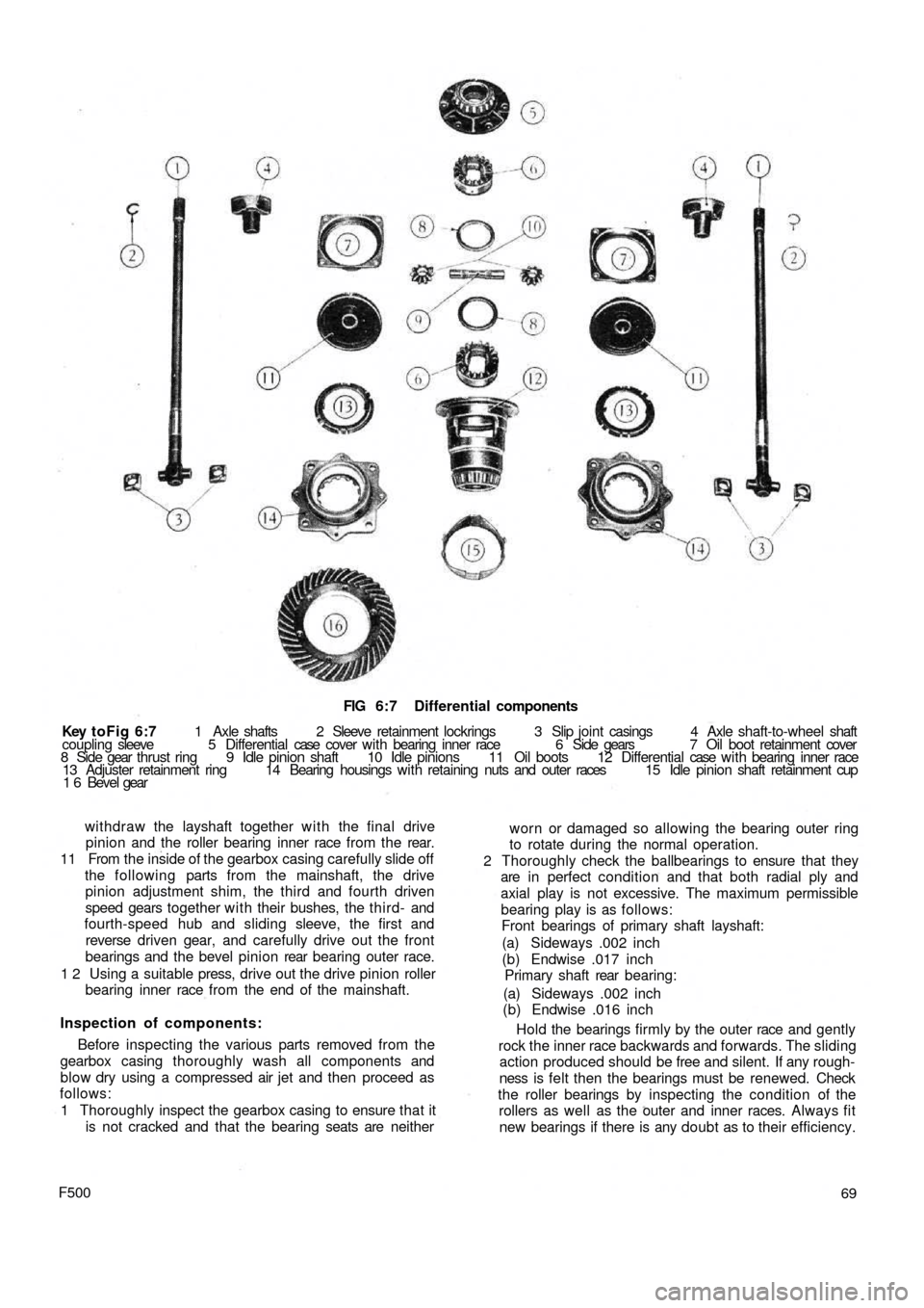
FIG 6:7 Differential components
Key toFig 6:7 1 Axle shafts 2 Sleeve retainment lockrings 3 Slip joint casings 4 Axle shaft-to-wheel shaft
coupling sleeve 5 Differential case cover w i t h bearing inner race 6 Side gears 7 Oil boot retainment cover
8 Side gear thrust ring 9 Idle pinion shaft 10 Idle pinions 11 Oil boots 12 Differential case w i t h bearing inner race
13 Adjuster retainment ring 14 Bearing housings with retaining nuts and outer races 15 Idle pinion shaft retainment cup
1 6 Bevel gear
withdraw the layshaft together w i t h the final drive
pinion and the roller bearing inner race from the rear.
11 From the inside of the gearbox casing carefully slide off
the following parts from the mainshaft, the drive
pinion adjustment shim, the third and fourth driven
speed gears together with their bushes, the t hird- and
fourth-speed hub and sliding sleeve, the first and
reverse driven gear, and carefully drive out the front
bearings and the bevel pinion rear bearing outer race.
1 2 Using a suitable press, drive out the drive pinion roller
bearing inner race from the end of the mainshaft.
Inspection of components:
Before inspecting the various parts removed from the
gearbox casing thoroughly wash all components and
blow dry using a compressed air jet and then proceed as
follows:
1 Thoroughly inspect the gearbox casing to ensure that it
is not cracked and that the bearing seats are neither
F50069 worn or damaged so allowing the bearing outer ring
to rotate during the normal operation.
2 Thoroughly check the ballbearings to ensure that they
are in perfect condition and that both radial ply and
axial play is not excessive. The maximum permissible
bearing play is as follows:
Front bearings of primary shaft layshaft:
(a) Sideways .002 inch
(b) Endwise .017 inch
Primary shaft rear bearing:
(a) Sideways .002 inch
(b) Endwise .016 inch
Hold the bearings firmly by the outer race and gently
rock the inner race backwards and forwards. The sliding
action produced should be free and silent. If any rough-
ness is felt then the bearings must be renewed. Check
the roller bearings by inspecting the condition of the
rollers as well as the outer and inner races. Always fit
new bearings if there is any doubt as to their efficiency.
Page 66 of 128
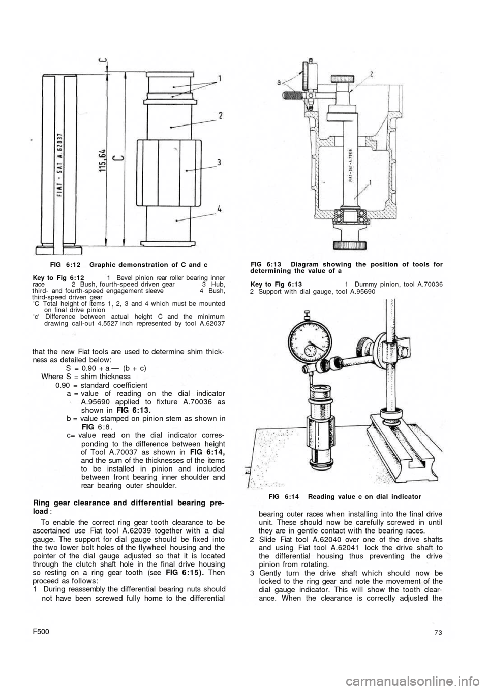
FIG 6:12 Graphic demonstration of C and c
Key to Fig 6:12 1 Bevel pinion rear roller bearing inner
race 2 Bush, fourth-speed driven gear 3 Hub,
third- and fourth-speed engagement sleeve 4 Bush,
third-speed driven gear
'C Total height of items 1, 2, 3 and 4 which must be mounted
on final drive pinion
'c' Difference between actual height C and the minimum
drawing call-out 4.5527 inch represented by tool A.62037
that the new Fiat tools are used to determine shim thick-
ness as detailed below:
S = 0.90 + a — (b + c)
Where S = shim thickness
0.90 = standard coefficient
a = value of reading on the dial indicator
A.95690 applied to fixture A.70036 as
shown in FIG 6:13.
b = value stamped on pinion stem as shown in
FIG 6:8.
c= value read o n the dial indicator corres-
ponding to the difference between height
of Tool A.70037 as shown in FIG 6:14,
and the sum of the thicknesses of the items
to be installed in pinion and included
between front bearing inner shoulder and
rear bearing outer shoulder.
Ring gear clearance and differential bearing pre-
load :
To enable the correct ring gear tooth clearance to be
ascertained use Fiat tool A.62039 together with a dial
gauge. The support for dial gauge should be fixed into
the t w o lower bolt holes of the flywheel housing and the
pointer of the dial gauge adjusted so that it is located
through the clutch shaft hole in the final drive housing
so resting on a ring gear tooth (see FIG 6:15). Then
proceed as follows:
1 During reassembly the differential bearing nuts should
not have been screwed fully home to the differential
F50073
bearing outer races w h e n installing into the f i n a l drive
unit. These should now be carefully screwed in until
they are in gentle contact with the bearing races.
2 Slide Fiat tool A.62040 over one of the drive shafts
and using Fiat tool A.62041 lock the drive shaft to
the differential housing thus preventing the drive
pinion from rotating.
3 Gently turn the drive shaft which should now be
locked to the ring gear and note the movement of the
dial gauge indicator. This will show the tooth clear-
ance. When the clearance is correctly adjusted the
FIG 6:14 Reading value c on dial indicator Key to Fig 6:13 1 Dummy pinion, tool A.70036
2 Support with dial gauge, tool A.95690 FIG 6:13 Diagram showing the position of tools for
determining the value of a
Page 69 of 128
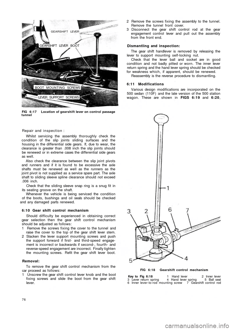
LEVER SUPPORT SCREWS BOOT MOUNTING SCREWSGEARSHIFT LEVER BOOT
GEARSHIFT LEVER
FIG 6:17 Location of gearshift lever on control passage
tunnel
Repair and inspection :
Whilst servicing the assembly thoroughly check the
condition of the slip joints sliding surfaces and the
housing in the differential side gears. If, due to wear, the
clearance is greater than .008 inch the slip joints should
be renewed or in extreme cases the differential side gears
as well.
Also check the clearance between the slip joint pivots
and runners and if it is found to be excessive the axle
shafts must be renewed as well as the runners as the
joint pivot is not supplied as a service spare part. The axle
shaft to sliding sleeve spline clearance should not exceed
.006 inch.
Check that the sliding sleeve snap ring is a snug fit in
its seating groove on the shaft.
Whenever the vehicle is being serviced the condition
of the boots, bushings and oil seals should be checked
and any damaged parts renewed.
6:10 Gear shift control mechanism
Should difficulty be experienced in obtaining correct
gear selection then the gear shift control mechanism
should be adjusted as follows:
1 Remove the screws fixing the cover to the tunnel and
raise t h e cover to t h e t o p of the gear shift lever stem.
2 Slacken the lever support mounting screws and push
the support forward if first- and third-speed engage-
ment is incorrect or backwards if second-, fourth- and
reverse-speed engagement are incorrect. Finally tighten
the mounting screws. Refit the gear shift lever boot.
Removal:
To remove the gear shift control mechanism from the
car proceed as follows:
1 Unscrew the gear shift control lever knob and the boot
fixing screws and slide the boot from the gear shift
lever.
76Key to Fig 6:18 1 Hand lever 2 Inner lever
3 Lever return spring 4 Hand lever spring 5 Ball seat
6 Inner lever-to-rod mounting screw 7 Gearshift control rod FIG 6:18 Gearshift control mechanism
6:11 Modifications
Various design modifications are incorporated on the
500 sedan (110F) and the late version of the 500 station
wagon. These are shown in FIGS 6:19 and 6:20, The gear shift handlever is removed by releasing the
lever to support mounting self-locking nut.
Check that the lever ball and socket are in good
condition and not badly pitted or worn. The inner lever
return spring and the hand lever spring should be checked
for weakness which, if apparent, should be renewed.
Reassembly is the reverse procedure to dismantling. Dismantling and inspection: 2 Remove the screws fixing the assembly to the tunnel.
Remove the tunnel front cover.
3 Disconnect the gear shift control rod at the gear
engagement control lever and pull out the assembly
from the front end.
Page 70 of 128
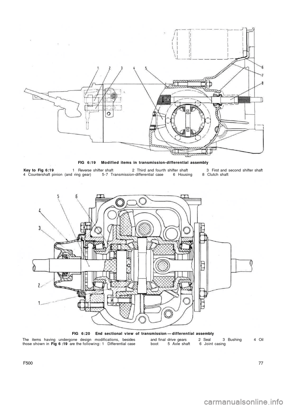
FIG 6:19 Modified items in transmission-differential assembly
Key to Fig 6:19 1 Reverse shifter shaft 2 Third and fourth shifter shaft 3 First and second shifter shaft
4 Countershaft pinion (and ring gear) 5 - 7 Transmission-differential case 6 Housing 8 Clutch shaft
FIG 6:20 End sectional view of transmission — differential assembly
The items having undergone design modifications, besides and final drive gears 2 Seal 3 Bushing 4 Oil
those shown in Fig 6 :19 are the following: 1 Differential case boot 5 Axle shaft 6 Joint casing
77F500
Page 73 of 128
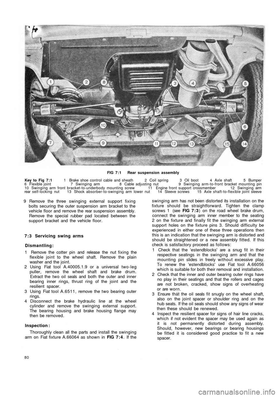
FIG 7 : 1 Rear suspension assembly
Key to Fig 7 : 1 1 Brake shoe control cable and sheath 2 Coil spring 3 Oil boot 4 Axle shaft 5 Bumper
6 Flexible joint 7 Swinging arm 8 Cable adjusting nut 9 Swinging arm-to-front bracket mounting pin
10 Swinging arm front bracket-to-underbody mounting screw 11 Engine front support crossmember 12 Swinging arm
rear self-locking nut 13 Shock absorber-to-swinging arm lower nut 14 Sleeve screws 15 Axle shaft-to-flexible joint sleeve
9 Remove the three swinging external support fixing
bolts securing the outer suspension arm bracket to the
vehicle floor and remove the rear suspension assembly.
Remove the special rubber pad located between the
support bracket and the vehicle floor.
7 : 3 Servicing swing arms
Dismantling:
1 Remove the cotter pin and release the nut fixing the
flexible joint to the wheel shaft. Remove the plain
washer and the joint.
2 Using Fiat tool A.40005.1.9 or a universal two-leg
puller, remove the wheel shaft and brake drum.
Extract the t w o oil seals and both the outer and inner
bearing inner rings, thrust ring of the joint and the
resilient spacer.
3 Using Fiat tool A.6511, remove the t w o bearing outer
rings.
4 Disconnect the brake hydraulic line at the wheel
cylinder and remove the swinging external support.
The bearing housing and brake housing flange may
then be removed.
Inspection :
Thoroughly clean all the parts and install the swinging
arm on Fiat fixture A.66064 as shown in FIG 7 : 4. If the
80
swinging arm has not been distorted its installation on the
fixture should be straightforward. Tighten the clamp
screws 1 (see FIG 7 : 3) on the road wheel brake drum,
connect the swinging arm inner member to the seating
2 on the fixture and finally fit the swinging arm external
support holes on the fixture pins 3. Should difficulty be
experienced in either one of these three operations then
this is an indication that the swinging arm is distorted and
should be straightened or a new assembly fitted. If this
check is satisfactory proceed as follows:
1 Check that the 'estendblocks' are a snug fit in their
respective seatings in the swinging arm and that the
mounting pin slides in freely w it h ou t excessive play.
To renew the 'estendblocks' use Fiat tool A.66056
which is suitable for both their removal and installation.
2 Check that the inner and outer bearing outer rings have
no play in their seatings and that the rollers and cages
are not broken, cracked, show signs of overheating
or are worn.
3 Ensure t h a t the o i l seals f i t snugly on the wheel shaft,
also on the joint spacer or shoulder ring and on the
hub seats. If the oil seals should show any signs of wear
then these should be renewed.
4 Inspect the resilient spacer for signs of hair line cracks,
which if not evident the spacer may be used again as
it is not permanently distorted during assembly.
Should, however, new bearings or bearing housings
be fitted it is considered good practice to fit a new
spacer.