technical specifications FIAT 500 1959 1.G Workshop Manual
[x] Cancel search | Manufacturer: FIAT, Model Year: 1959, Model line: 500, Model: FIAT 500 1959 1.GPages: 128, PDF Size: 9.01 MB
Page 11 of 128

INTAKEEXHAUSTINTAKEEXHAUST
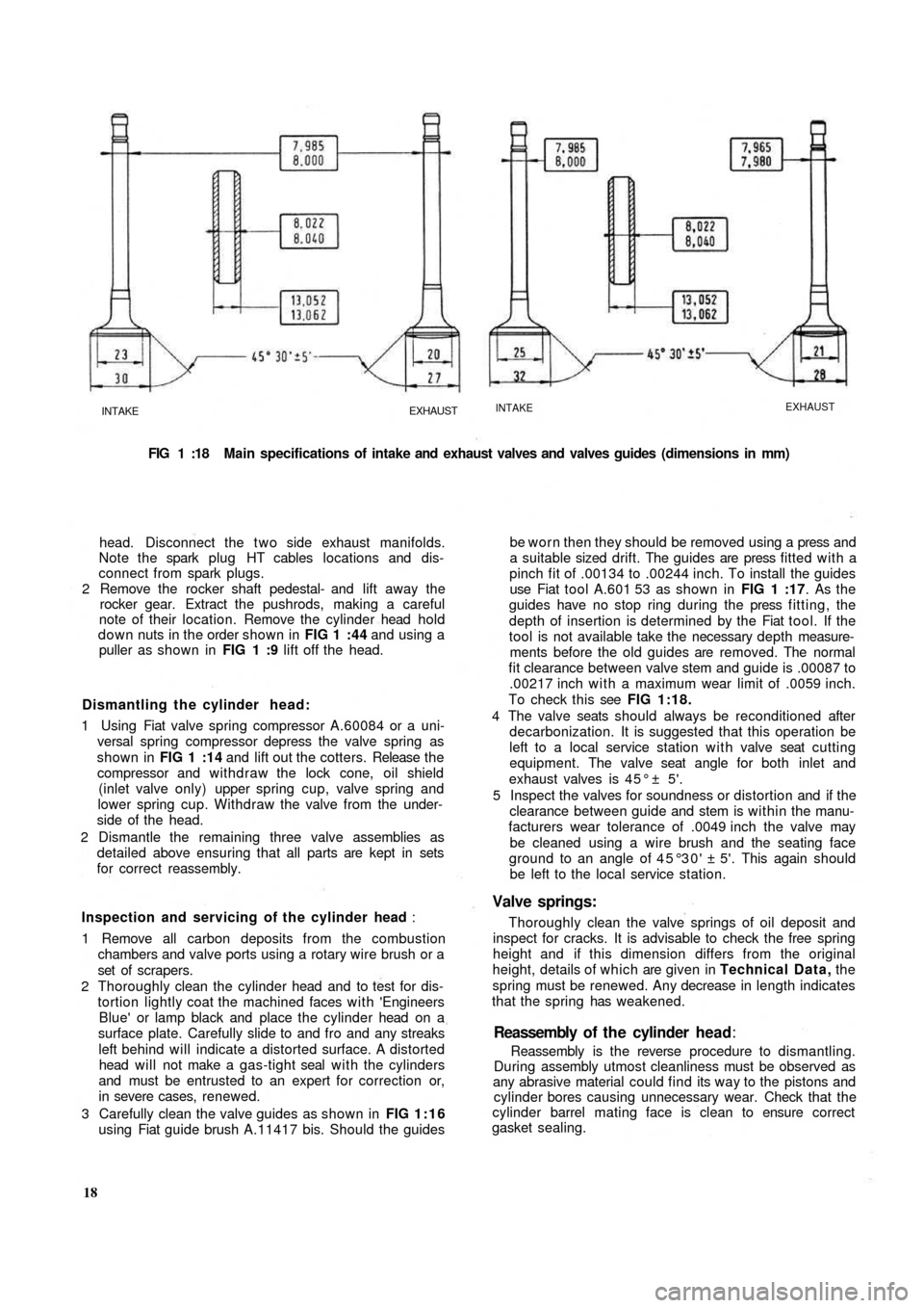
FIG 1 :18 Main specifications of intake and exhaust valves and valves guides (dimensions in mm)
head. Disconnect the t w o side exhaust manifolds.
Note the spark plug HT cables locations and dis-
connect from spark plugs.
2 Remove the rocker shaft pedestal- and lift away the
rocker gear. Extract the pushrods, making a careful
note of their location. Remove the cylinder head hold
down nuts in the order shown in FIG 1 :44 and using a
puller as shown in FIG 1 :9 lift off the head.
Dismantling the cylinder head:
1 Using Fiat valve spring compressor A.60084 or a uni-
versal spring compressor depress the valve spring as
shown in FIG 1 :14 and lift out the cotters. Release t h e
compressor and withdraw the lock cone, oil shield
(inlet valve only) upper spring cup, valve spring and
lower spring cup. Withdraw the valve from the under-
side of the head.
2 Dismantle the remaining three valve assemblies as
detailed above ensuring that all parts are kept in sets
for correct reassembly.
Inspection and servicing of the cylinder head :
1 Remove all carbon deposits from the combustion
chambers and valve ports using a rotary wire brush or a
set of scrapers.
2 Thoroughly clean the cylinder head and to test for dis-
tortion lightly coat the machined faces with 'Engineers
Blue' or lamp
black and place the cylinder head on a
surface plate. Carefully slide to and fro and any streaks
left behind will indicate a distorted surface. A distorted
head will not make a gas-tight seal with the cylinders
and must be entrusted to an expert for correction or,
in severe cases, renewed.
3 Carefully clean the valve guides as shown in FIG 1:16
using Fiat guide brush A.11417 bis. Should the guides
18Reassembly is the reverse procedure to dismantling.
During assembly utmost cleanliness must be observed as
any abrasive material could find its way to the pistons and
cylinder bores causing unnecessary wear. Check that the
cylinder barrel mating face is clean to ensure correct
gasket sealing.Reassembly of t h e cylinder head:
be worn then they should be removed using a press and
a suitable sized drift. The guides are press fitted with a
pinch fit of .00134 to .00244 inch. To install the guides
use Fiat tool A.601 53 as shown in FIG 1 :17. As the
guides have no stop ring during the press fitting, the
depth of insertion is determined by the Fiat tool. If the
tool is not available take the necessary depth measure-
ments before the old guides are removed. The normal
fit clearance between valve stem and guide is .00087 to
.00217 inch with a maximum wear limit of .0059 inch.
To check this see FIG 1:18.
4 The valve seats should always be reconditioned after
decarbonization. It is suggested that this operation be
left to a local service station with valve seat cutting
equipment. The valve seat angle for both inlet and
exhaust valves is 4 5 ° ± 5'.
5 Inspect the valves for soundness or distortion and if the
clearance between guide and stem is within the manu-
facturers wear tolerance of .0049 inch the valve may
be cleaned using a wire brush and the seating face
ground to an angle of 45°30' ± 5'. This again should
be left to the local service station.
Valve springs:
Thoroughly clean the valve springs of oil deposit and
inspect for cracks. It is advisable to check the free spring
height and if this dimension differs from the original
height, details of which are given in Technical Data, the
spring must be renewed. Any decrease in length indicates
that the spring has weakened.
Page 76 of 128

high bearing preload. To reset remove the wheel shaft
and fit a new resilient spacer. Repeat the rotation
torque test.
Swinging arm adjustment:
To adjust the swinging arm use Fiat fixture A.66064 as
shown in FIG 7 : 3 and proceed as follows:
1 At points A and B as indicated in FIG 7 : 4 between the
'estendblock' and the swinging arm to body front
mounting bracket fit three shims on each side. To
ensure that the shims are correctly centred use Fiat
alignment bar A.66057.
2 Whilst removing the alignment bar, carefully slip in the
mounting pin and screw on the nut. Once the rear
wheel geometry adjustment has been completed this
nut should be tightened to a torque wrench setting
of 43.4 to 50.6 Ib ft.
3 At points C and D (see FIG 7 : 4) , insert the number of
shims required to fill in the gap between the 'estend-
block' and the two fixture shoulders. Having deter-
mined the number of shims required both at locations
C and D, these must later be fitted between the
'estendblock' and the shoulders on the swinging arm
to body mounting bracket.
7 : 4 Coil springs
The coil springs should be thoroughly cleaned and all
traces of rust removed. Inspect the spring coils for hair
line cracks, which if evident, a new pair of springs must
be fitted to ensure correct vehicle height and stability.
Check the free
height and the height under loading of
the coil springs and these must correspond to the figures
quoted in Technical Data.
7:5 Installation of rear suspension assembly
To replace the rear suspension assembly proceed as
follows:
1 Insert the swinging arm inner end in the mounting
bracket which is welded onto the body floor. Place
between the 'estendblock' and bracket the number of
adjustment shims as previously determined using Fiat
fixture A.66064 as shown in FIG 7 : 4. Insert the Fiat
alignment bar A.66057 through 'estendblock' and
shims, aligning them with the holes in the mounting
bracket. Firmly hold the entire assembly using a garage
hydraulic jack if necessary, and carefully remove the
alignment bar and at the same time ease in t h e
mounting pin. Secure the nut which once the rear
wheels geometry has been checked must be tightened
to a torque wrench setting of 43.4 to 50.6 Ib/ft.
2 Screw in finger tight the three swinging arm external
bracket to body floor mounting screws together w i t h
the plain and spring washers. The screws will have to
be tightened to a torque wrench setting of 28.9 to
36.2 Ib/ft once the rear wheel geometry has been
adjusted.
3 Carefully insert the coil spring, lower insulator ring
onto the swinging arm, insert the spring on the shock
absorber which should be previously secured to the
arm and position the spring onto its seat on the arm.
Place the upper insulator ring onto the spring, raise the
suspension assembly using a garage hydraulic jack and
insert the spring onto its seating under the body floor.
F50083 4 Ensure that the shock absorber to floor rubber ring has
been correctly fitted and extend the shock absorber
until its upper mounting pin protrudes into the vehicle
through the hump in the floor panel. Secure the shock
absorber by its mounting nut and lockwasher having
first inserted the rubber ring and plain washer.
5 Refit the rear wheel housing in place, reconnect the
brake line to the connection on body floor and remove
the plug from the output hole in the brake fluid
reservoir. Bleed the hydraulic brake system as
described in Chapter 10.
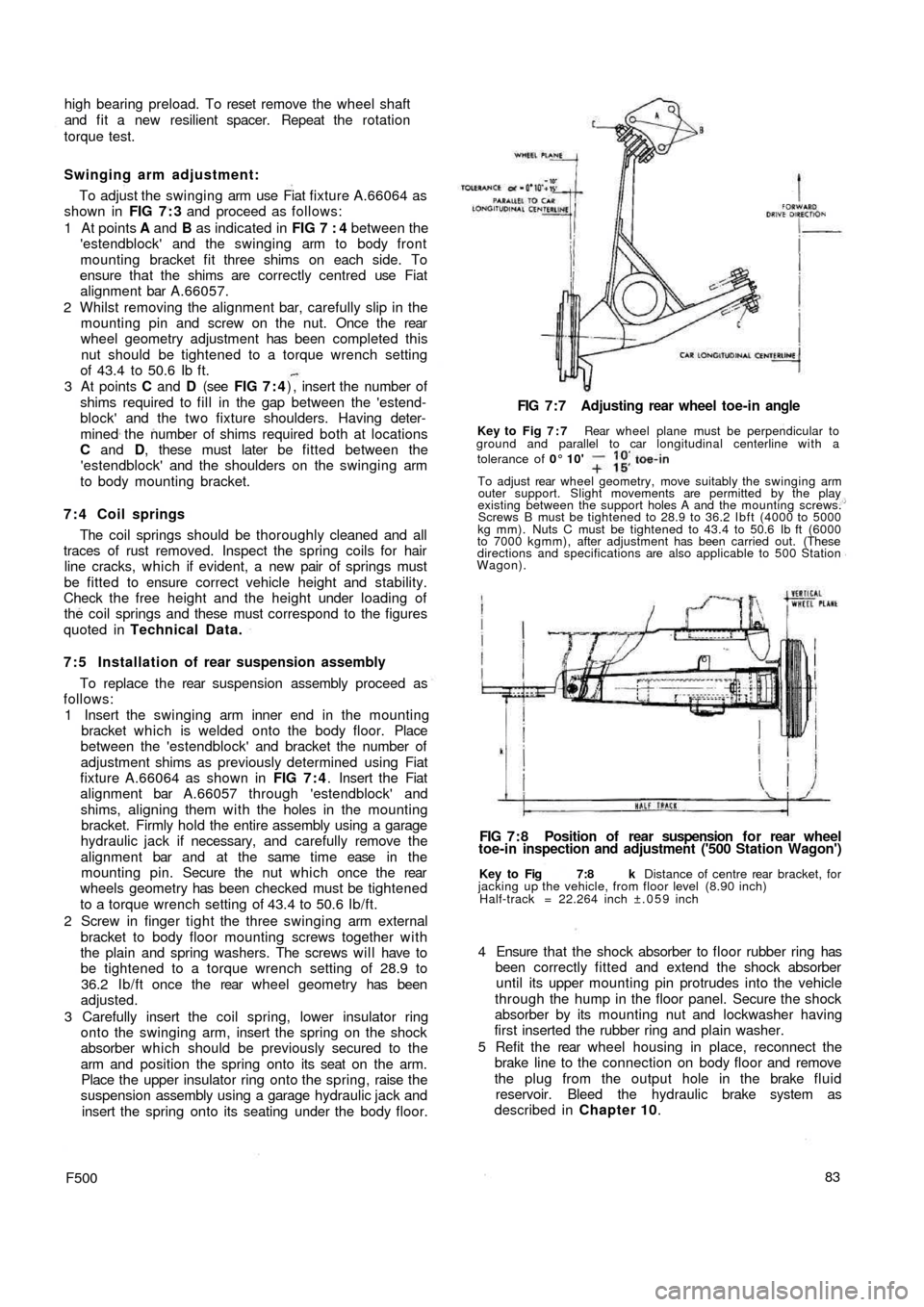
Key to Fig 7:8 k Distance of centre rear bracket, for
jacking up the vehicle, from floor level (8.90 inch)
Half-track = 22.264 inch ±.059 inch
FIG 7 : 8 Position of rear suspension f o r rear wheel
toe-in inspection and adjustment ('500 Station Wagon') FIG 7 : 7 Adjusting rear wheel toe-in angle
Key to Fig 7 : 7 Rear wheel plane must be perpendicular to
ground and parallel to car longitudinal centerline with a
tolerance of 0° 10'
To adjust rear wheel geometry, move suitably the swinging arm
outer support. Slight movements are permitted by the play
existing between the support holes A and the mounting screws.
Screws B must be tightened to 28.9 to 36.2 Ibft (4000 to 5000
kg mm). Nuts C must be tightened to 43.4 to 50.6 Ib ft (6000
to 7000 kgmm), after adjustment has been carried out. (These
directions and specifications are also applicable to 500 Station
Wagon).