ad blue FIAT 500 1960 1.G Workshop Manual
[x] Cancel search | Manufacturer: FIAT, Model Year: 1960, Model line: 500, Model: FIAT 500 1960 1.GPages: 128, PDF Size: 9.01 MB
Page 11 of 128
INTAKEEXHAUSTINTAKEEXHAUST
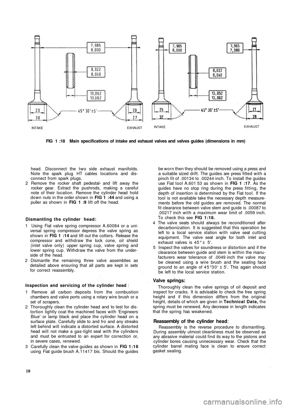
FIG 1 :18 Main specifications of intake and exhaust valves and valves guides (dimensions in mm)
head. Disconnect the t w o side exhaust manifolds.
Note the spark plug HT cables locations and dis-
connect from spark plugs.
2 Remove the rocker shaft pedestal- and lift away the
rocker gear. Extract the pushrods, making a careful
note of their location. Remove the cylinder head hold
down nuts in the order shown in FIG 1 :44 and using a
puller as shown in FIG 1 :9 lift off the head.
Dismantling the cylinder head:
1 Using Fiat valve spring compressor A.60084 or a uni-
versal spring compressor depress the valve spring as
shown in FIG 1 :14 and lift out the cotters. Release t h e
compressor and withdraw the lock cone, oil shield
(inlet valve only) upper spring cup, valve spring and
lower spring cup. Withdraw the valve from the under-
side of the head.
2 Dismantle the remaining three valve assemblies as
detailed above ensuring that all parts are kept in sets
for correct reassembly.
Inspection and servicing of the cylinder head :
1 Remove all carbon deposits from the combustion
chambers and valve ports using a rotary wire brush or a
set of scrapers.
2 Thoroughly clean the cylinder head and to test for dis-
tortion lightly coat the machined faces with 'Engineers
Blue' or lamp
black and place the cylinder head on a
surface plate. Carefully slide to and fro and any streaks
left behind will indicate a distorted surface. A distorted
head will not make a gas-tight seal with the cylinders
and must be entrusted to an expert for correction or,
in severe cases, renewed.
3 Carefully clean the valve guides as shown in FIG 1:16
using Fiat guide brush A.11417 bis. Should the guides
18Reassembly is the reverse procedure to dismantling.
During assembly utmost cleanliness must be observed as
any abrasive material could find its way to the pistons and
cylinder bores causing unnecessary wear. Check that the
cylinder barrel mating face is clean to ensure correct
gasket sealing.Reassembly of t h e cylinder head:
be worn then they should be removed using a press and
a suitable sized drift. The guides are press fitted with a
pinch fit of .00134 to .00244 inch. To install the guides
use Fiat tool A.601 53 as shown in FIG 1 :17. As the
guides have no stop ring during the press fitting, the
depth of insertion is determined by the Fiat tool. If the
tool is not available take the necessary depth measure-
ments before the old guides are removed. The normal
fit clearance between valve stem and guide is .00087 to
.00217 inch with a maximum wear limit of .0059 inch.
To check this see FIG 1:18.
4 The valve seats should always be reconditioned after
decarbonization. It is suggested that this operation be
left to a local service station with valve seat cutting
equipment. The valve seat angle for both inlet and
exhaust valves is 4 5 ° ± 5'.
5 Inspect the valves for soundness or distortion and if the
clearance between guide and stem is within the manu-
facturers wear tolerance of .0049 inch the valve may
be cleaned using a wire brush and the seating face
ground to an angle of 45°30' ± 5'. This again should
be left to the local service station.
Valve springs:
Thoroughly clean the valve springs of oil deposit and
inspect for cracks. It is advisable to check the free spring
height and if this dimension differs from the original
height, details of which are given in Technical Data, the
spring must be renewed. Any decrease in length indicates
that the spring has weakened.
Page 42 of 128
a n 0—20 v o ltmeter. If the circuit is in order the meter
should read approximately 12-volts.
3 Battery to fuse box terminal 30. Connect the volt-
meter between the terminal 30 and earth. No reading
indicates a faulty cable or loose connection.
4 Fuse box. Connect the voltmeter between the other
auxiliary terminal 30 and earth. No reading indicates a
broken or loose connection.
5 Fuse box auxiliary terminal 30 to terminal
number 30 on ignition switch. Connect the meter
between terminal number 30 on the ignition switch
and earth. No reading indicates a damaged cable or
loose connection.
6 Ignition switch. Connect the meter between termi-
nal 15/54 and earth. Switch onto the ignition position,
when no reading indicates a fault in the switch.
7 Ignition switch to low-tension cable connection
on the coil (blue cable). Connect the meter
between ignition coil terminal (blue cable) and earth.
No reading indicates a damaged cable or loose con-
nection.
8 Ignition coil. Disconnect the black low-tension cable
connecting the coil to the distributor side terminal at
the coil and connect the meter between this terminal
and earth. No reading indicates a fault in the primary
winding of the coil and a replacement coil must be
fitted. If the reading is correct remake the connections
to the coil.
9 Ignition coil to distributor. Disconnect the thin
black low-tension cable at the side of the distributor
and connect the meter between the end of this cable
and earth. No reading indicates a damaged cable or
loose connections.
10 Contact breaker and capacitor. Connect the
meter across the contact breaker points. No reading
indicates a faulty capacitor.
Capacitor:
The best method of testing a capacitor (condenser) is
by substitution. Disconnect the original capacitor and
connect a new one between the low-tension terminal on
the side of the distributor and earth.
If a new capacitor is needed, fit a new one complete
w i t h bracket, but if necessary unsolder the original bracket
and solder it onto the new capacitor using as little heat as
possible. Capacitor capacity is .15-.20 microfarads.
3 : 5 Removing and dismantling distributor (sedan
and sports)
To remove the distributor proceed as follows:
1 Rotate the engine slowly until the distributor rotor arm
is opposite the brass segment in the distributor cap
connected to No. 1 plug lead. This will provide a datum
for replacement.
2 Disconnect the cable from the low-tension terminal on
the side of the distributor body. Mark position of distri-
butor on support. Release the distributor retaining nut
and washer from the underside of the top flange of the
distributor support and carefully lift away the dis-
tributor.
3 Pull off the rotor arm. Remove the insulated terminal
assembly from the side of distributor body. Release the
contact breaker carrier plate retaining screws and con-
denser flange screw from the outside of the distributor
F50049 body. Carefully lift out the contact breaker plate
assembly.
4 Before further dismantling note the relative positions of
the driving dog and the rotor arm driving slot at the top
of the distributor cam spindle. The driving dog is offset
and can only engage its driving spindle in one position.
Then when the cam assembly is fitted to the centrifugal
weights during reassembly the timing is not 180 deg.
out.
5 Take out the cam lubrication felt pad recessed in the
rotor arm housing on the end of the cam spindle.
Remove the retaining screw, carefully disengage the
springs and lift out the cam spindle. It should be noted
that there is a small retaining ball and spring located in a
drilling nearly at the top of the drive shaft spindle.
Carefully lift away the weights.
6 Thoroughly clean all parts and inspect for excessive
wear. The distributor cap must not be cracked or show
signs of tracking. The cap terminals, rotor and contact
breaker points can be cleaned with a very fine file.
Emerypaper must not be used. If the clearance between
the rotor and distributor cap segments exceeds .0118
inch both the rotor and distributor cap must be replaced.
Inspect the contact breaker arm rubbing block for exces-
sive wear and also the points for wear so that if the gap
exceeds the last setting limit of .0209 inch and adjust-
ment through the stationary contact carrier screw is no
longer possible (see FIG 3 : 2) , the contact breaker set
must be renewed.
If the distributor drive shaft side or vertical movement is
excessive the distributor must be renewed.
Weak centri-
fugal weight springs or damaged weights must be
renewed using original Fiat spares otherwise the auto-
matic ignition advance characteristics could be altered.
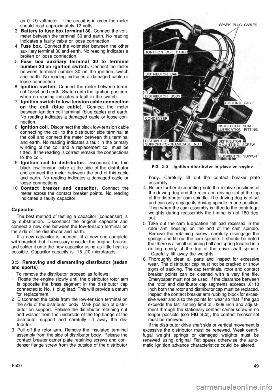
FIG 3 : 3 Ignition distributor in place on engine SPARK PLUG CABLES
IGNITION COIL CABLE!
DISTRIBUTOR CAP
DISTRIBUTOR BODY
GROUND CABLE
CONDENSER
DISTRIBUTOR SHAFT
LUBRICATION FITTING
DISTRIBUTORSUPPORT-TO--CRANKCASE NUT
[MOUNTING SCREWDISTRIBUTOR
DISTRIBUTOR SUPPORT
Page 67 of 128
TOOL A 62039
TOOLA. 62040 PIN WRENCH A. 52022
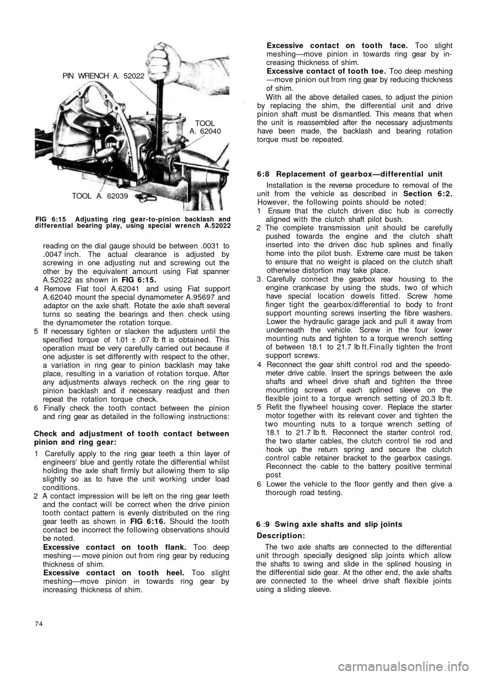
FIG 6:15 Adjusting ring gear-to-pinion backlash and
differential bearing play, using special wrench A.52022
reading on the dial gauge should be between .0031 to
.0047 inch. The actual clearance is adjusted by
screwing in one adjusting nut and screwing out the
other by the equivalent amount using Fiat spanner
A.52022 as shown in FIG 6:15.
4 Remove Fiat tool A.62041 and using Fiat support
A.62040 mount the special dynamometer A.95697 and
adaptor on the axle shaft. Rotate the axle shaft several
turns so seating the bearings and then check using
the dynamometer the rotation torque.
5 If necessary tighten or slacken the adjusters until the
specified torque of 1.01 ± .07 lb ft is obtained. This
operation must be very carefully carried out because if
one adjuster is set differently with respect to the other,
a variation in ring gear to pinion backlash may take
place, resulting in a variation of rotation torque. After
any adjustments always recheck on the ring gear to
pinion backlash and if necessary readjust and then
repeat the rotation torque check.
6 Finally check the tooth contact between the pinion
and ring gear as detailed in the following instructions:
Check and adjustment of tooth contact between
pinion and ring gear:
1 Carefully apply to the ring gear teeth a thin layer of
engineers' blue and gently rotate the differential whilst
holding the axle shaft firmly but allowing them to slip
slightly so as to have the unit working under load
conditions.
2 A contact impression will be left on the ring gear teeth
and the contact will be correct when the drive pinion
tooth contact pattern is evenly distributed on the ring
gear teeth as shown in FIG 6:16. Should the tooth
contact be incorrect the following observations should
be noted.
Excessive contact on tooth flank. Too deep
meshing — move pinion out from ring gear by reducing
thickness of shim.
Excessive contact on tooth heel. Too slight
meshing—move pinion in towards ring gear by
increasing thickness of shim.
74
6 : 8 Replacement of gearbox—differential unit
Installation is the reverse procedure to removal of the
unit from the vehicle as described in Section 6:2.
However, the following points should be noted:
1 Ensure that the clutch driven disc hub is correctly
aligned with the clutch shaft pilot bush.
2 The complete transmission unit should be carefully
pushed towards the engine and the clutch shaft
inserted into the driven disc hub splines and finally
home into the pilot bush. Extreme care must be taken
to ensure that no weight is placed on the clutch shaft
otherwise distortion may take place.
3 Carefully connect the gearbox rear housing to the
engine crankcase by using the studs, t w o of which
have special location dowels fitted. Screw home
finger tight the gearbox/differential to body to front
support mounting screws inserting the fibre washers.
Lower the hydraulic garage jack and pull it away from
underneath the vehicle. Screw in the four lower
mounting nuts and tighten to a torque wrench setting
of between 18.1 to 21.7 Ib f t.Finally tighten the front
support screws.
4 Reconnect the gear shift control rod and the speedo-
meter drive cable. Insert the springs between the axle
shafts and wheel drive shaft and tighten the
three
mounting screws of each splined sleeve on the
flexible joint to a torque wrench setting of 20.3 Ib ft.
5 Refit the flywheel housing cover. Replace the starter
motor together with its relevant cover and tighten the
two mounting nuts to a torque wrench setting of
18.1 to 21.7 Ib ft. Reconnect the starter control rod,
the t w o starter cables, the clutch control tie rod and
hook up the return spring and secure the clutch
control cable retainer bracket to the gearbox casings.
Reconnect the cable to the battery positive terminal
post
6 Lower the vehicle to the floor gently and then give a
thorough road testing.
6 :9 Swing axle shafts and slip joints
Description:
The t w o axle shafts are connected to the differential
unit through specially designed slip joints which allow
the shafts to swing and slide in the splined housing in
the differential side gear. At the other end, the axle shafts
are connected to the wheel drive shaft flexible joints
using a sliding sleeve. Excessive contact on tooth face. Too slight
meshing—move pinion in towards ring gear by in-
creasing thickness of shim.
Excessive contact of tooth toe. Too deep meshing
—move pinion out from ring gear by reducing thickness
of shim.
With all the above detailed cases, to adjust the pinion
by replacing the shim, the differential unit and drive
pinion shaft must be dismantled. This means that when
the unit is reassembled after the necessary adjustments
have been made, the backlash and bearing rotation
torque must be repeated.
Page 97 of 128
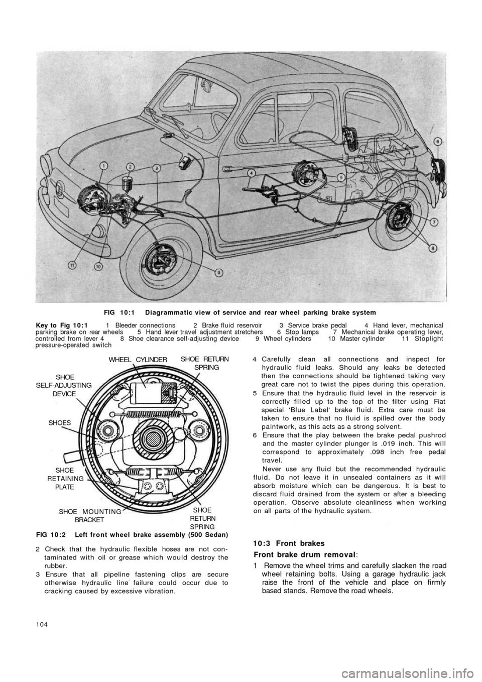
FIG 10:1 Diagrammatic view of service and rear wheel parking brake system
Key to Fig 10:1 1 Bleeder connections 2 Brake fluid reservoir 3 Service brake pedal 4 Hand lever, mechanical
parking brake on rear wheels 5 Hand lever travel adjustment stretchers 6 Stop lamps 7 Mechanical brake operating lever,
controlled from lever 4 8 Shoe clearance self-adjusting device 9 Wheel cylinders 10 Master cylinder 11 Stoplight
pressure-operated switch
FIG 10:2 Left front wheel brake assembly (500 Sedan)
SHOE
RETURN
SPRINGSHOE MOUNTING
BRACKET SHOE
RETAINING
PLATE SHOES
DEVICESHOE
SELF-ADJUSTING
WHEEL CYLINDERSHOE RETURNSPRING
2 Check that the hydraulic flexible hoses are not con-
taminated with oil or grease which would destroy the
rubber.
3 Ensure that all pipeline fastening clips are secure
otherwise hydraulic line failure could occur due to
cracking caused by excessive vibration.
104
4 Carefully clean all connections and inspect for
hydraulic fluid leaks. Should any leaks be detected
then the connections should be tightened taking very
great care not to twist the pipes during this operation.
5 Ensure that the hydraulic fluid level in the reservoir is
correctly filled up to the top of the filter using Fiat
special 'Blue Label' brake fluid. Extra care must be
taken to ensure that no fluid is spilled over the body
paintwork, as this acts as a strong solvent.
6 Ensure that the play between the brake pedal pushrod
and the master cylinder plunger is .019 inch. This will
correspond to approximately .098 inch free pedal
travel.
Never use any fluid but the recommended hydraulic
fluid. Do not leave it in unsealed containers as it will
absorb moisture which can be dangerous. It is best to
discard fluid drained from the system or after a bleeding
operation. Observe absolute cleanliness when working
on all parts of the hydraulic system.
10:3 Front brakes
Front brake drum removal:
1 Remove the wheel trims and carefully slacken the road
wheel retaining bolts. Using a garage hydraulic jack
raise the front of the vehicle and place on firmly
based stands. Remove the road wheels.
Page 102 of 128
10:9 Brake fluid reservoir
The reservoir is located in the front compartment to the
side of the fuel tank as shown in FIG 10:9. Should it be
necessary to detach the fluid outlet line from the reservoir
the outlet hole must be blanked off using a tapered
wooden peg of suitable length so that the cap may be
replaced to prevent the ingress of foreign matter into
the reservoir and the absorbtion of moisture, oil or petrol
vapours which would alter the properties of the hydraulic
fluid.
A special filter is fitted into the top of the reservoir
through which all fluid used for topping-up the reservoir
must pass to ensure utmost inner cleanliness of the
hydraulic system.
10:10 Bleeding the system
This is not a routine maintenance operation and is only
necessary if air has entered the hydraulic system because
parts have been dismantled or because the f l u i d level in
the reservoir has dropped so low that air has been drawn
into the main feed pipe to the master cylinders.
1 Fill the reservoir w i t h Fiat 'Blue Label' hydraulic fluid.
During the bleeding operation fluid will be used and
constant topping-up of the supply reservoir will be
needed. If this is not done it is possible for air to enter
the master cylinder main feed pipe which will nullify
the operation and necessitate a fresh start.
2 Attach a length of rubber or plastic tubing to the
bleeder screw on the rear wheel cylinder furthermost
from the master cylinder. Immerse the free end of the
tube in a small volume of hydraulic brake fluid in a
clean jar.
3 Open the bleed screw one turn and get a second
operator to press down slowly on the brake pedal. After
a full stroke let the pedal return without assistance,
pause a moment and repeat the d o w n stroke. At first
there will be air bubbles issuing from the bleed tube,
but when fluid alone is ejected, hold the pedal firmly
down on the floor panel and tighten the bleed screw.
Repeat this operation on the other rear brake and then
repeat the operation on the two front brakes.
4 On completion, top-up the fluid in the reservoir to the
correct level. Discard all dirty fluid. If fluid is perfectly
clean, let it stand for twenty four hours to become
clear of air bubbles before using it again.
10:11 Hand parking brake
Normally with the new 500 Sedan model automatic
brake adjusting device, adjustment of the rear brakes
will take up excessive handbrake travel.
If there is excessive travel on the handbrake of the
Sedan model at any time, or in the case of Station Wagon
model even after the rear brakes have been manually
adjusted, suspect worn brake shoe linings or stretched
handbrake cables. Examine the linings and fit replace-
ment shoes if necessary. Check the action of the hand
parking brake again and if there is still too much travel
before the brakes are applied it is permissible to take up as
follows:
1 It is essential to ensure that the rear shoes are correctly
adjusted as described in Section 10:2.
2 Apply the hand parking brake lever until the pawl
engages with the ratchet at the second notch.
F500
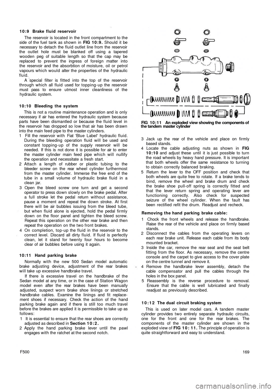
FIG 10:11 An exploded view showing the components of
the tandem master cylinder
3 Jack up the rear of t h e vehicle and place on firmly
based stands.
4 Locate the cable adjusting nuts as shown in FIG
10:10 and adjust these until it is just possible to turn
the road wheels by heavy hand pressure. It is important
that both wheels offer the same resistance to turning
to obtain correctly balanced braking.
5 Return the lever to the OFF position and check that
both wheels are quite free to rotate. If a brake tends to
bind, remove the wheel and brake drum and check
the brake shoe pull-off spring is correctly fitted and
that the lever return spring and operating lever are
functioning correctly. Also check for suspected
seizure of the wheel cylinder. When the fault has
been rectified refit the drum. Readjust and recheck.
Removing the hand parking brake cable:
1 Chock the front wheels and release the handbrake.
Raise t h e rear of the vehicle and place on firmly based
stands.
2 Disconnect the cables from the operating levers on
each rear brake unit. Release each cable from its body
mounted bracket.
3 Inside the car, remove the rear seat and the seat belt
fitting from the floor. As necessary, remove the centre
console and the carpet to give access to the cover plate
on the centre tunnel and remove it.
4 Remove the handbrake lever assembly, detach the
cable compensator and pull the cables through the
holes in the box panel.
5 Reassembly is the reverse procedure to removal.
Ensure t h a t the cable is well lubricated and finally
readjust as previously described.
10:12 The dual circuit braking system
This is used on later model cars. A tandem master
cylinder provides t w o entirely separate hydraulic circuits,
one for the front and one for the rear brakes. The
components of the master cylinder are shown in the
exploded view of FIG 1 0 : 1 1 . The principle of operation is
quite straightforward and easy to understand.
169