fuel reserve FIAT 500 1960 1.G Workshop Manual
[x] Cancel search | Manufacturer: FIAT, Model Year: 1960, Model line: 500, Model: FIAT 500 1960 1.GPages: 128, PDF Size: 9.01 MB
Page 30 of 128
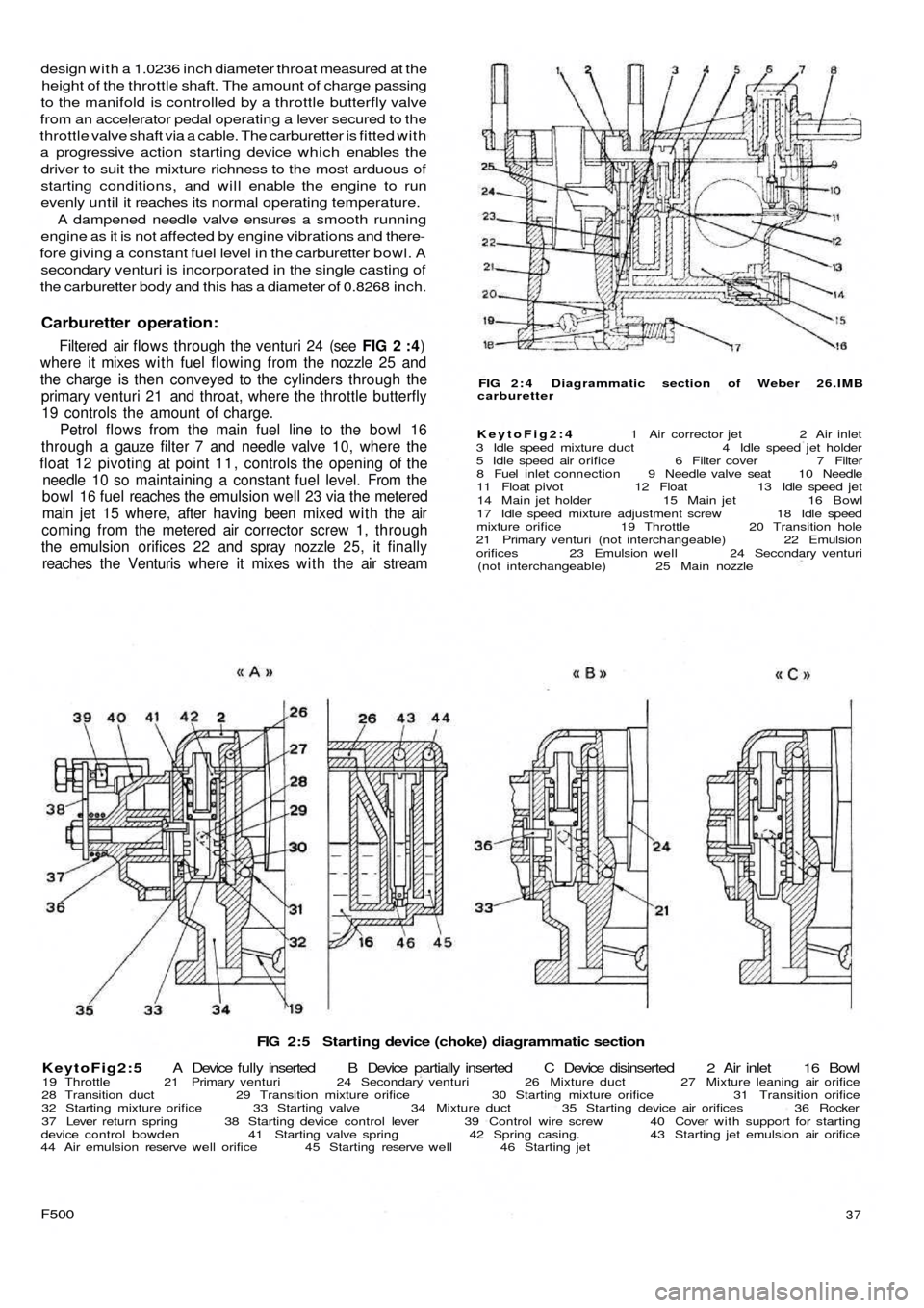
FIG 2:5 Starting device (choke) diagrammatic section
KeytoFig2:5 A Device fully inserted B Device partially inserted C Device disinserted 2 Air inlet 16 Bowl
19 Throttle 21 Primary venturi 24 Secondary venturi 26 Mixture duct 27 Mixture leaning air orifice
28 Transition duct 29 Transition mixture orifice 30 Starting mixture orifice 31 Transition orifice
32 Starting mixture orifice 33 Starting valve 34 Mixture duct 35 Starting device air orifices 36 Rocker
37 Lever return spring 38 Starting device control lever 39 Control wire screw 40 Cover with support for starting
device control bowden 41 Starting valve spring 42 Spring casing. 43 Starting jet emulsion air orifice
44 Air emulsion reserve well orifice 45 Starting reserve well 46 Starting jet
F50037
FIG 2 : 4 Diagrammatic section of Weber 26.IMB
carburetter
KeytoFig2:4 1 Air corrector jet 2 Air inlet
3 Idle speed mixture duct 4 Idle speed jet holder
5 Idle speed air orifice 6 Filter cover 7 Filter
8 Fuel inlet connection 9 Needle valve seat 10 Needle
11 Float pivot 12 Float 13 Idle speed jet
14 Main jet holder 15 Main jet 16 Bowl
17 Idle speed mixture adjustment screw 18 Idle speed
mixture orifice 19 Throttle 20 Transition hole
21 Primary venturi (not interchangeable) 22 Emulsion
orifices 23 Emulsion well 24 Secondary venturi
(not interchangeable) 25 Main nozzle
design with a 1.0236 inch diameter throat measured at the
height of the throttle shaft. The amount of charge passing
to the manifold is controlled by a throttle butterfly valve
from an accelerator pedal operating a lever secured to the
throttle valve shaft via a cable. The carburetter is fitted with
a progressive action starting device which enables the
driver to suit the mixture richness to the most arduous of
starting conditions, and will enable the engine to run
evenly until it reaches its normal operating temperature.
A dampened needle valve ensures a smooth running
engine as it is not affected by engine vibrations and there-
fore giving a constant fuel level in the carburetter bowl. A
secondary venturi is incorporated in the single casting of
the carburetter body and this has a diameter of 0.8268 inch.
Carburetter operation:
Filtered air flows through the venturi 24 (see FIG 2 :4)
where it mixes w i t h fuel flowing from the nozzle 25 and
the charge is then conveyed to the cylinders through the
primary venturi 21 and throat, where the throttle butterfly
19 controls the amount of charge.
Petrol flows from the main fuel line to the bowl 16
through a gauze filter 7 and needle valve 10, where the
float 12 pivoting at point 1 1 , controls the opening of the
needle 10 so maintaining a constant fuel level. From the
bowl 16 fuel reaches the emulsion well 23 via the metered
main jet 15 where, after having been mixed with the air
coming from the metered air corrector screw 1, through
the emulsion orifices 22 and spray nozzle 25, it finally
reaches the Venturis where it mixes w i t h the air stream
Page 31 of 128
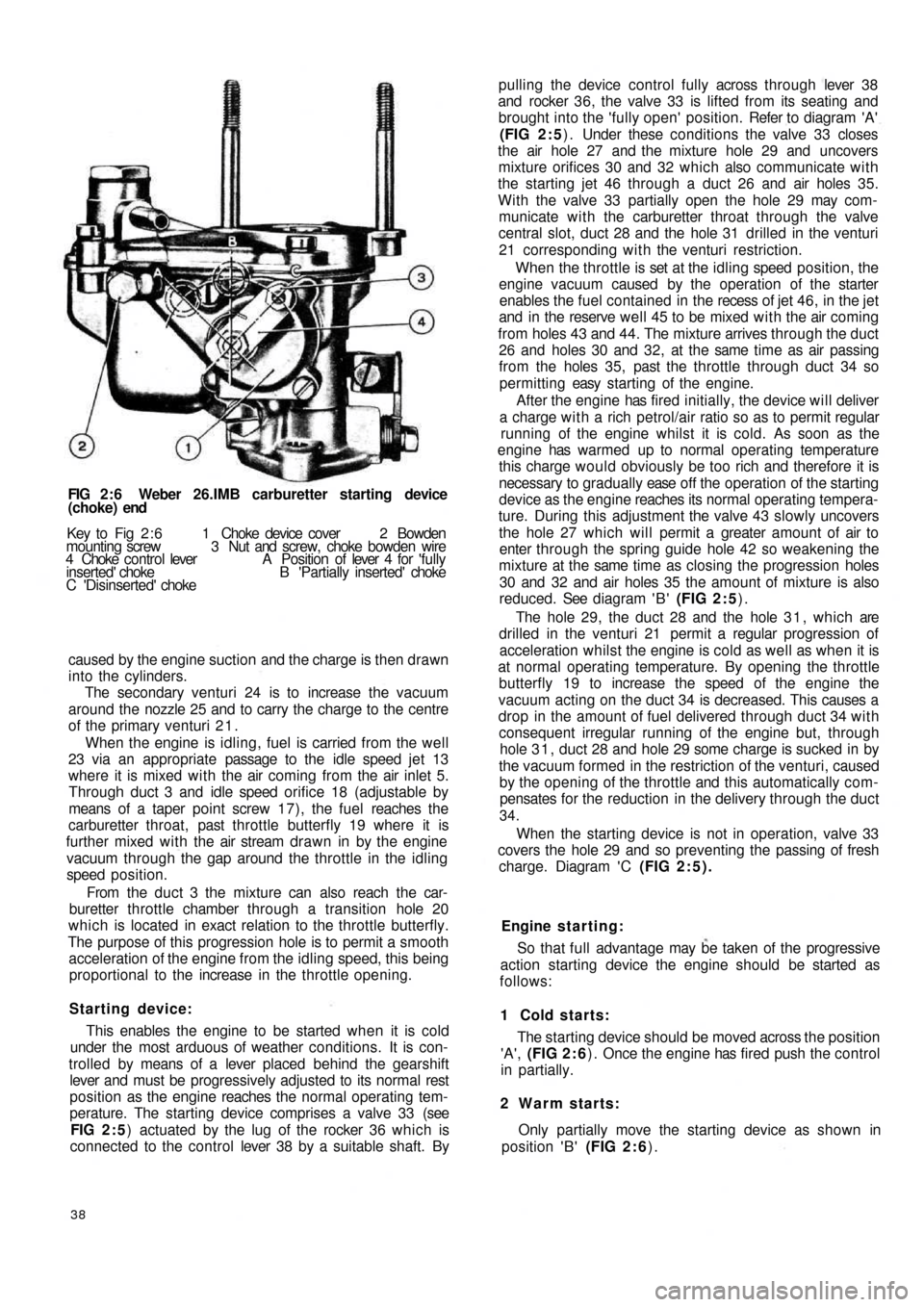
FIG 2 : 6 Weber 26.IMB carburetter starting device
(choke) end
Key to Fig 2 : 6 1 Choke device cover 2 Bowden
mounting screw 3 Nut and screw, choke bowden wire
4 Choke control lever A Position of lever 4 for 'fully
inserted' choke B 'Partially inserted' choke
C 'Disinserted' choke
caused by the engine suction and the charge is then drawn
into the cylinders.
The secondary venturi 24 is to increase the vacuum
around the nozzle 25 and to carry the charge to the centre
of the primary venturi 2 1 .
When the engine is idling, fuel is carried from the well
23 via an appropriate passage to the idle speed jet 13
where it is mixed with the air coming from the air inlet 5.
Through duct 3 and idle speed orifice 18 (adjustable by
means of a taper point screw 17), the fuel reaches the
carburetter throat, past throttle butterfly 19 where it is
further mixed with the air stream drawn in by the engine
vacuum through the gap around the throttle in the idling
speed position.
From the d u c t 3 the mixture can also reach the car-
buretter throttle chamber through a transition hole 20
which is located in exact relation to the throttle butterfly.
The purpose of this progression hole is to permit a smooth
acceleration of the engine from the idling speed, this being
proportional to the increase in the throttle opening.
Starting device:
This enables the engine to be started when it is cold
under the most arduous of weather conditions. It is con-
trolled by means of a lever placed behind the gearshift
lever and must be progressively adjusted to its normal
rest
position as the engine reaches the normal operating tem-
perature. The starting device comprises a valve 33 (see
FIG 2 : 5) actuated by the lug of the rocker 36 which is
connected to the control lever 38 by a suitable shaft. By
38
pulling the device control fully across through lever 38
and rocker 36, the valve 33 is lifted from its seating and
brought into the 'fully open' position. Refer to diagram 'A'
(FIG 2 : 5) . Under these conditions the valve 33 closes
the air hole 27 and the mixture hole 29 and uncovers
mixture orifices 30 and 32 which also communicate with
the starting jet 46 through a duct 26 and air holes 35.
With the valve 33 partially open the hole 29 may com-
municate with the carburetter throat through the valve
central slot, duct 28 and the hole 31 drilled in the venturi
21 corresponding with the venturi restriction.
When the throttle is set at the idling speed position, the
engine vacuum caused by the operation of the starter
enables the fuel contained in the recess of jet 4 6 , in the jet
and in the reserve well 45 to be mixed w i t h the air coming
from holes 43 and 44. The mixture arrives through the duct
26 and holes 30 and 32, at the same time as air passing
from the holes 35, past the throttle through duct 34 so
permitting easy starting of the engine.
After the engine has fired initially, the device will deliver
a charge with a rich petrol/air ratio so as to permit regular
running of the engine whilst it is cold. As soon as the
engine has warmed up to normal operating temperature
this charge would obviously be too rich and therefore it is
necessary to gradually ease o f f the operation of the starting
device as the engine reaches its normal operating tempera-
ture. During this adjustment the valve 43 slowly uncovers
the hole 27 which will permit a greater amount of air to
enter through the spring guide hole 42 so weakening the
mixture at the same time as closing the progression holes
30 and 32 and air holes 35 the amount of mixture is also
reduced. See diagram ' B ' (FIG 2 : 5).
The hole 29, the duct 28 and the hole 3 1 , which are
drilled in the venturi 21 permit a regular progression of
acceleration whilst the engine is cold as well as when it is
at normal operating temperature. By opening the throttle
butterfly 19 to increase the speed of the engine the
vacuum acting on the duct 34 is decreased. This causes a
drop in the amount of fuel delivered through duct 34 with
consequent irregular running of the engine but, through
hole 3 1 , duct 28 and hole 29 some charge is sucked in by
the vacuum formed in the restriction of the venturi, caused
by the opening of the throttle and this automatically com-
pensates for the reduction in the delivery through the duct
34.
When the starting device is not in operation, valve 33
covers the hole 29 and so preventing the passing of fresh
charge. Diagram ' C (FIG 2:5).
Engine s t a rting:
So that full advantage may be taken of the progressive
action starting device the engine should be started as
follows:
1 Cold starts:
The starting device should be moved across the position
'A', (FIG 2 : 6) . Once the engine has fired push the control
in partially.
2 Warm starts:
Only partially move the starting device as shown in
position 'B' (FIG 2 : 6).
Page 34 of 128
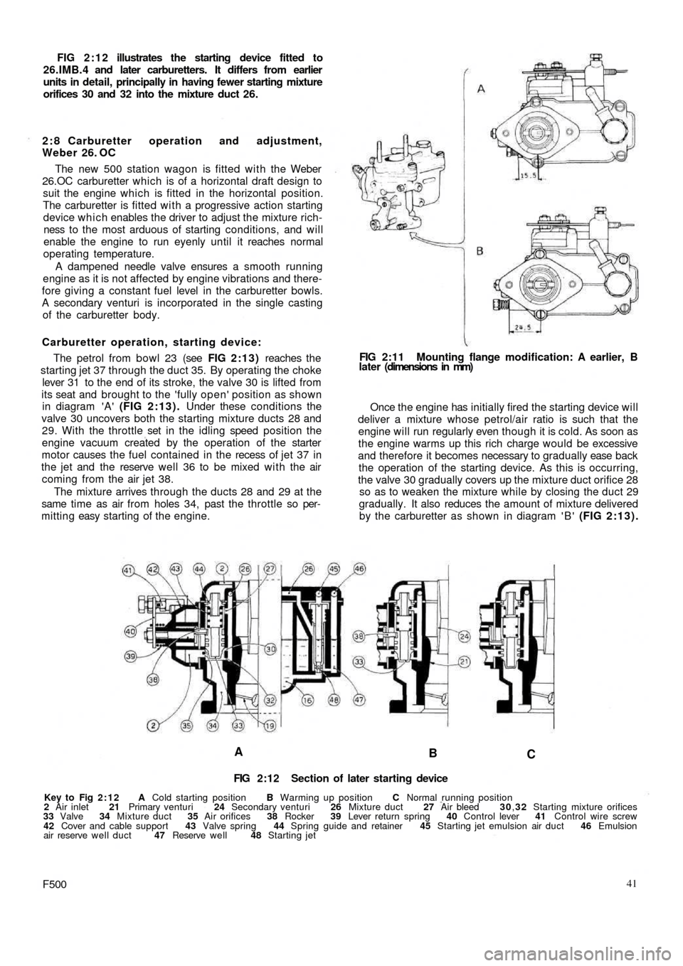
FIG 2:12 illustrates the starting device fitted to
26.IMB.4 and later carburetters. It differs from earlier
units in detail, principally in having fewer starting mixture
orifices 30 and 32 into the mixture duct 26.
2 : 8 Carburetter operation and adjustment,
Weber 26. OC
The new 500 station wagon is fitted with the Weber
26.OC carburetter which is of a horizontal draft design to
suit the engine which is fitted in the horizontal position.
The carburetter is fitted with a progressive action starting
device which enables the driver to adjust the mixture rich-
ness to the most arduous of starting conditions, and will
enable the engine to run eyenly until it reaches normal
operating temperature.
A dampened needle valve ensures a smooth running
engine as it is not affected by engine vibrations and there-
fore giving a constant fuel level in the carburetter bowls.
A secondary venturi is incorporated in the single casting
of the carburetter body.
Carburetter operation, starting device:
The petrol from bowl 23 (see FIG 2:13) reaches the
starting jet 37 through the duct 35. By operating the choke
lever 31 to the end of its stroke, the valve 30 is lifted from
its seat and brought to the 'fully open' position as shown
in diagram 'A' (FIG 2:13). Under these conditions the
valve 30 uncovers both the starting mixture ducts 28 and
29. With the throttle set in the idling speed position the
engine vacuum created by the operation of the starter
motor causes the fuel contained in the recess of j e t 37 in
the jet and the reserve
well 36 to be mixed with the air
coming from the air jet 38.
The mixture arrives through the ducts 28 and 29 at the
same time as air from holes 34, past the throttle so per-
mitting easy starting of the engine.
A
B
C
FIG 2:12 Section of later starting device
Key to Fig 2:12 A Cold starting position B Warming up position C Normal running position
2 Air inlet 21 Primary venturi 24 Secondary venturi 26 Mixture duct 27 Air bleed 30,32 Starting mixture orifices
33 Valve 34 Mixture duct 35 Air orifices 38 Rocker 39 Lever return spring 40 Control lever 41 Control wire screw
42 Cover and cable support 43 Valve spring 44 Spring guide and retainer 45 Starting jet emulsion air duct 46 Emulsion
air reserve well duct 47 Reserve well 48 Starting jet
F50041 Once the engine has initially fired the starting device will
deliver a mixture whose petrol/air ratio is such that the
engine will run regularly even though it is cold. As soon as
the engine warms up this rich charge would be excessive
and therefore it becomes necessary to gradually ease back
the operation of the starting device. As this is occurring,
the valve 30 gradually covers up the mixture duct orifice 28
so as to weaken the mixture while by closing the duct 29
gradually. It also reduces the amount of mixture delivered
by the carburetter as shown in diagram ' B ' (FIG 2:13). FIG 2:11 Mounting flange modification: A earlier, B
later (dimensions in mm)
Page 35 of 128
3938
28 29 30A3132 33
28 29 30 3.1B28
29 30 31C
34 34
34
37 36 35 23
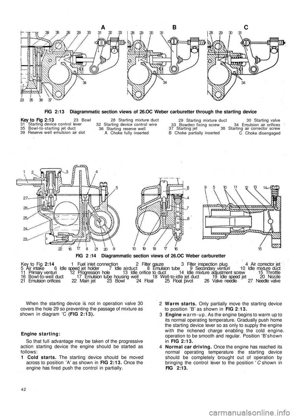
FIG 2:13 Diagrammatic section views of 26.OC Weber carburetter through the starting device
1
2.34
5
27
26.
25,
24.
23.
22
1617
8
21
209
_6
.4
7
.8
10 19 1817
16 1595
1011
1213
14.
FIG 2 :14 Diagrammatic section views of 26.OC Weber carburetter
Key to Fig 2:14 1 Fuel inlet connection 2 Filter gauze 3 Filter inspection plug 4 Air corrector jet
5 Air intake 6 Idle speed jet holder 7 Idle airduct 8 Emulsion tube 9 Secondary venturi 10 Idle mixture duct
11 Primary venturi 12 Progression hole 13 Idle orifice to duct 14 Idle mixture adjustment screw 15 Throttle
16 B o w l - t o - w e l l duct 17 Emulsion tube housing well 18 Well-to-idle jet duct 19 Idle speed jet 20 Nozzle
21 Emulsion orifices 22 Main jet 23 Bowl 24 Float 25 Float pivot 26 Valve needle 27 Needle valve
When the starting device is not in operation valve 30
covers the hole 29 so preventing the passage of mixture as
shown in diagram 'C (FIG 2:13).
Engine starting:
So that full advantage may be taken of the progressive
action starting device the engine should be started as
follows:
1 Cold starts. The starting device should be moved
across to position 'A' as shown in FIG 2:13. Once the
engine has fired push the control in partially.
42
2 Warm starts. Only partially move the starting device
to position ' B ' as shown in FIG 2:13.
3 Engine warm-up. As the engine begins to warm up to
its normal operating temperature. Gradually push home
the starting device lever so as only to supply the engine
with the richened charge enabling the cold engine.
operation to be smooth and regular. Position ' B ' s h o w n
in FIG 2:13.
4 Normal car driving. Once the engine has reached its
normal operating temperature the starting device
should be completely brought out of operation by
bringing the control lever to the position C shown in
FIG 2:13. Key t o Fig 2 : 1 3
23 Bowl 28 Starting mixture duct
29 Starting mixture duct30 Starting valve
34 Emulsion air orifices
38 Starting air corrector screw
C Choke disengaged B Choke partially inserted 37 Starting jet33 Bowden fixing screw
A Choke fully inserted 36 Starting reserve well 32 Starting device control wire 31 Starting device control lever
35 Bowl-to-starting jet duct
39 Reserve well emulsion air slot
Page 38 of 128
Air cleaner—station wagon:
A pleated paper air cleaner element is housed in a
special air intake chamber connected to the front of the
engine air cooling cowling (see FIG 4 : 2) . This chamber
will be seen located towards the rear of t h e power unit
compartment. Remove the retaining wing nut, lift off the
lid and the element can be withdrawn by lifting upwards.
2:10 Blow-by-gases recirculation device
Engine 110 F.000
All the oil vapours and blow-by-gases that are formed
in the engine crankcase are drawn to the cylinder head
cover recess 1 (see FIG 2:18). From here they travel into
the pipe 5 via a breather valve 2 which is firmly attached to
the oil filler cap 3 and the strainer 4 located in the filler
neck. The oil vapours and gases are then d r a w n back into
the duct 9 from the pipe 5 which connects the air cleaner
6 to the carburetter 7. This ensures a complete closed cir-
cuit circulation.
Engine 120.000:
From engine No. 288156 the oil vapours and blow-by-
gases instead of being exhausted to the atmosphere are
conveyed to the air cleaner and from here they are drawn
back into the combustion chambers. To ensure that an
excessive of oil vapour does not pass along the piping
with the blow-by-gases a diaphragm is fitted in the duct
in front of the breather valve 2 (see FIG 2 :18), the dia-
phragm comprising a filter gauze 11 and moveable parti-
tion 10.
It should be noted that the oil vapour strainer 4 (see
FIG 2:18) and the flame trap 8 can easily be removed
from their seating for cleaning or renewal.
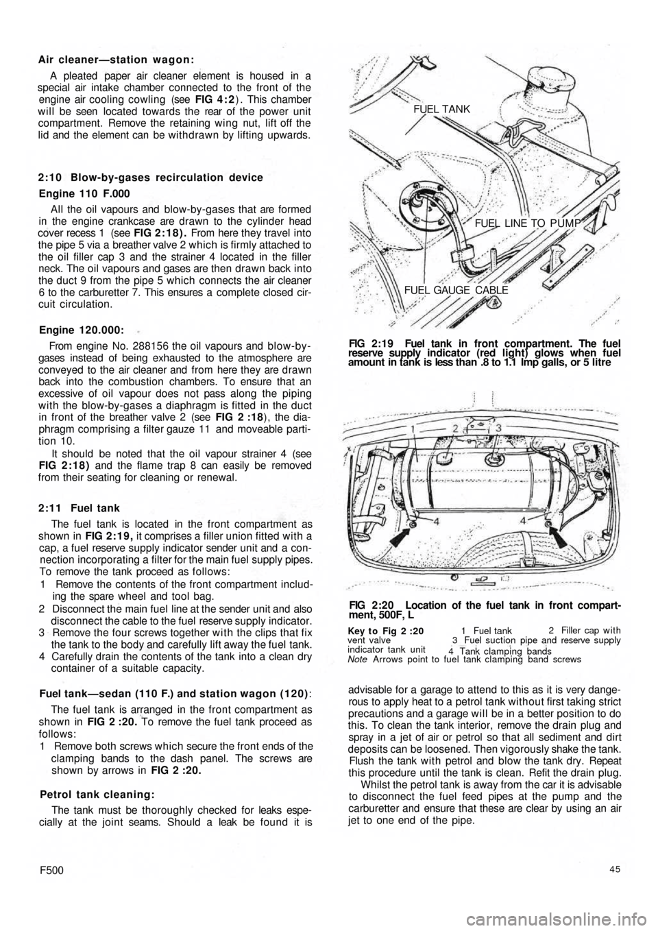
2 : 1 1 Fuel tank
The fuel tank is located in the front compartment as
shown in FIG 2:19, it comprises a filler union fitted with a
cap, a fuel reserve supply indicator sender unit and a con-
nection incorporating a filter for the main fuel supply pipes.
To remove the tank proceed as follows:
1 Remove the contents of the front compartment includ-
ing the spare wheel and tool bag.
2 Disconnect the main fuel line at the sender unit and also
disconnect the cable to the fuel reserve supply indicator.
3 Remove the four screws together w i t h the clips that fix
the tank to the body and carefully lift away the fuel tank.
4 Carefully drain the contents of the tank into a clean dry
container of a suitable capacity.
Fuel tank—sedan (110 F.) and station wagon (120):
The fuel tank is arranged in the front compartment as
shown in FIG 2 :20. To remove the fuel tank proceed as
follows:
1 Remove both screws which secure the front ends of the
clamping bands to the dash panel. The screws are
shown by arrows in FIG 2 :20.
Petrol tank cleaning:
The tank must be thoroughly checked for leaks espe-
cially at the joint seams. Should a leak be found it is
F50045
advisable for a garage to attend to this as it is very dange-
rous to apply heat to a petrol tank without first taking strict
precautions and a garage will be in a better position to do
this. To clean the tank interior, remove the drain plug and
spray in a jet of air or petrol so that all sediment and dirt
deposits can be loosened. Then vigorously shake the tank.
Flush the tank w i t h petrol and blow the tank dry. Repeat
this procedure until the tank is clean. Refit the drain plug.
Whilst the petrol tank is away from the car it is advisable
to disconnect the fuel feed pipes at the pump and the
carburetter and ensure that these are clear by using an air
jet to one end of the pipe.
Key t o Fig 2 :20
Note Arrows point to fuel tank clamping band screws vent valve
indicator tank unit1 Fuel tank2 Filler cap with
3 Fuel suction pipe and reserve supply
4 Tank clamping bands
FIG 2:20 Location of the fuel tank in front compart-
ment, 500F, L FIG 2:19 Fuel tank in front compartment. The fuel
reserve supply indicator (red light) glows when fuel
amount in tank is less than .8 to 1.1 Imp galls, or 5 litre FUEL TANK
FUEL LINE TO PUMP
FUEL GAUGE CABLE
Page 116 of 128
Lamp brilliance varies w i t h the speed of t h e car:
Check the condition of the battery. Examine the battery
connections. Make sure they are tight and renew faulty
cables.
11:10 Panel and warning lights:
All the gauges are clustered in a single instrument
mounted on the dashboard above the steering column.
Incorporated in this cluster is the parking light pilot light,
generator charge indicator, fuel reserve supply indicator,
low oil pressure indicator, and the speedometer w i t h
mileage recorder.
The parking lamp indicator glows green when the
ignition lock switch key is in either position 1 or 2 once
the toggle switch on the instrument panel has been
operated.
The generator charge indicator shows red only when
the ignition is turned on. It should be extinguished when
the generator output is sufficient for battery charge
(12.6 ± 0.2 volts) with the engine running at a speed
of 1100 rev/min and the headlights switched off.
The fuel reserve supply indicator shows red only when
the ignition is turned on and the amount of fuel in the
petrol tank has dropped to approximately .8 to 1.1
Imp. gallons.
The low oil pressure indicator shows red only when the
ignition is turned on and should be extinguished when
the oil pressure reaches 7.1 to 21.3 Ib/sq in, and opens
the sending unit contacts. Once the engine is at normal
operating temperature but at a speed below 1000 rev/
min the indicator might light up even the pressure is under
control and with normal operation.
All the bulbs fitted to the above described units are of
the tubular 2.5W type and to renew a bulb extract the
bulb holder from the rear of t h e instrument cluster and
release the bulb which is attached by a normal bayonet
coupling.
Fuel reserve supply indicator sender u n i t:
The fuel reserve supply indicator should be checked for
correct indication by allowing the fuel tank to empty and
then inserting .8 to 1.1 Imp. gallons at which stage the
light should extinguish. Any failure to do so should be
checked as follows:
1 Ensure that the indicator bulb operates correctly.
2 Check for complete circuit between the sender unit and
the indicator bulb.
3 If the sender unit float bracket is distorted the bulb
will
indicate a reserve supply of fuel greater or smaller than
specified. The bracket should be adjusted to give
correct indication of fuel level.
4 The sender unit could have been inadvertantly
damaged in which case the unit must be renewed.
11 :11 The horn
The horn circuit comprises the horn, push button at the
centre of the steering wheel and normal earth return
electrical circuit through the car body. One terminal is
connected to the battery whilst the other to the push
button on the steering wheel which when the button is
depressed the circuit will be closed so causing the horn
to operate.
F500
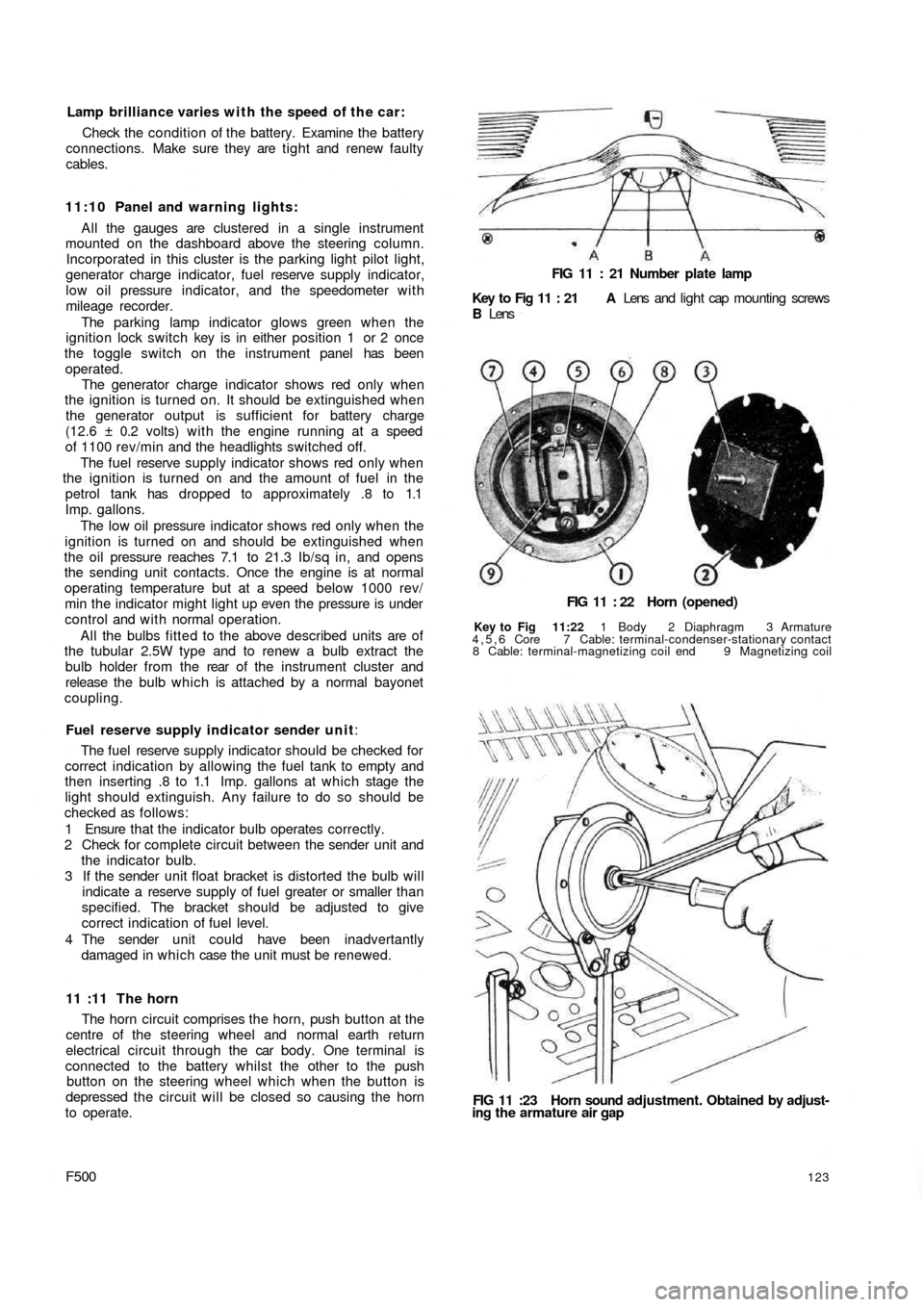
FIG 11 : 21 Number plate lamp
Key to Fig 11 : 21 A Lens and light cap mounting screws
B Lens
FIG 11 : 22 Horn (opened)
Key to Fig 11:22 1 Body 2 Diaphragm 3 Armature
4,5,6 Core 7 Cable: terminal-condenser-stationary contact
8 Cable: terminal-magnetizing coil end 9 Magnetizing coil
FIG 11 :23 Horn sound adjustment. Obtained by adjust-
ing the armature air gap
123