seats FIAT 500 1961 1.G User Guide
[x] Cancel search | Manufacturer: FIAT, Model Year: 1961, Model line: 500, Model: FIAT 500 1961 1.GPages: 128, PDF Size: 9.01 MB
Page 63 of 128
3 Check the layshaft and the primary shaft between
centres and using a dial gauge ensure that there is no
distortion. The out of true reading for bearing seats
should be less than .0008 inch. Inspect the splines and
ensure that the side and outerfaces are not indented.
Replace if there are signs of wear. Also inspect the
reverse shaft to ensure that it is perfectly smooth and
not showing signs of pitting or partial seizure.
4 Carefully inspect all gear teeth for signs of excessive
wear or damage. The contact faces must be smooth and
show no signs of indentation marks. Also check that
the backlash between the gears, when correctly
mounted on the surface plate is not greater than .0039
inch. The maximum wear limit is .0079 inch. Check that
the quick engagement front teeth of the second-, third-
and fourth-speed gears are not damaged or excessively
worn. Renew if there are signs of gearchange lever
misuse.
5 Inspect the sliding sleeves and the relevent hubs, ensure
that all the working surfaces are perfectly smooth. The
clearance between the mating parts should not be
greater than .0059 inch. Also inspect the meshing teeth
and ensure that they are in good condition.
6 Check that the gear shifting selector forks are not dis-
torted and that the striker rods freely slide in their seats
in the gearbox casing.
7 Carefully inspect that all the oil seals are in perfect con-
dition and if there is any doubt they should be renewed.
8 Inspect the striker rod locking balls and the safety rollers
and ensure that they slide freely in their seatings. Also
check the ball load spring efficiency and if this shows
signs of weakness then it should be renewed. Any
faults with these items will cause difficulty in engaging
gears or autodisengagement during engine acceleration.
6 : 4 Reassembly—gearbox
To reassemble the components to the gearbox ensure
that all components are thoroughly clean and then pro-
ceed as follows:
1 Press t h e pinion rear roller bearing onto the layshaft.
Install the layshaft in the casing, and at the same time
fit the adjustment shim, the fourth-speed driven gear
together w i t h its bush, the sleeve and hub for third and
fourth gear engagement, the first-speed and reverse
driven gear and the third-speed driven gear with its
hub.
2 Install the front layshaft ballbearing securing the
bearing retainment plate w i t h the screws and finally
lock the screws in position.
3 Insert the primary shaft together with the first, third
and fourth driving gear train in the gearbox housing
and slide t h e rear bearing onto the shaft. Push the
input shaft forward to enable the clutch shaft coupling
to be inserted in t h e rear and to be pulled up the
primary shaft by means of the pin. Do not forget the
retaining ring.
4 Slide the primary shaft backwards so pushing the rear
bearing into its bore. Refit the front bearing onto the
primary shaft.
5 On the layshaft insert the second-speed driven shaft
and bush, the second gear sliding dog sleeve and the
hub. Also insert the second-speed striker rod and the
first-speed fork. Do not forget to fit the safety roller
into its seating.
70
6 Slide the second-speed driving gear onto the primary
shaft. Place the engagement fork on the third- and
fourth-speed engagement sliding sleeve, and insert
the striker rod, lock the relevent fork and fit the safety
roller.
7 Insert the third safety roller and install the reverse shaft
and insert the reverse gear cluster onto it and secure
the shaft by tightening its block bolt. Install the reverse
striker rod w i t h its relevent fork.
8 Now refit the speedometer drive worm gear onto the
layshraft. Tighten the nuts on the primary shaft and the
layshaft, not forgetting to interpose the plain washer
between the speedometer driving worm and the nut,
to a torque wrench setting of 1 8.1 Ib ft to 25.3 Ib ft
(primary shaft) and 28.9 to 36.2 Ib ft (layshaft). It is
recommended that the input shaft and layshaft are
locked together by engaging t w o gears at the same
time. Finally, fit the splitpins.
9 Lock the shifter forks onto their shafts by tightening
their respective bolts and bend up the special locking
plates. Install the three positioning balls and relevant
springs into their bores and refit the cover plate.
10 Install the casing cover together with its relevant
gasket. This will enable correct positioning of the shift
shaft lever so that it engages in the outer ends of the
shifter shafts protruding from the gearbox casing.
11 Install the speedometer drive support on the gearbox
casing and refit the upper gearbox cover.
For subsequent differential operations and adjustments
see Sections 6:6.
6:5 Dismantling—differential and final drive
For the removal of the differential and final drive unit
from the gearbox refer to Section 6:3. To dismantle the
differential assembly
proceed as follows:
1 Remove the retaining ring 2 (see FIG 6 : 7) retaining
the splined sleeve 4 and slide the sleeve off the drive
shaft.
2 Remove t h e retaining covers 7 and the oil boots all
together with the bushes and seals, adjuster ring lock
rings 13, adjuster rings housing 14, and bearing
adjuster and roller bearing outer races.
3 Separate the differential housing halves by unscrewing
and removing the six bolts that keep both the halves and
the crownwheel together. It is advisable to mark the
respective components to ensure correct matching
upon reassembly.
4 Remove the differential pinion shaft retainer ring, also
the differential pinions 10 by removing the shaft and
withdrawing the two axle shafts 1.
5 Remove the differential side gears 6 and relevent thrust
rings 8.
6 Using a press remove the differential bearing inner
races from their seats on the carrier halves.
7 Thoroughly clean all parts and dry using a compressed
air jet.
Inspection:
The components of the differential unit must be
thoroughly inspected for correct operation and to deter-
mine the presence of any wear, damage or other irregulari-
ties. To check the items concerned proceed as follows:
1 Check thoroughly the idle pinion carrier shaft for signs
Page 64 of 128
of wear, distorting or unevenness of the surfaces as this
part is very heavily pressed when the vehicle is negotia-
ting a corner. If the clearance to the idle pinions exceeds
.0059 inch the shaft must be renewed.
2 Inspect the ring gear and pinion seat, the side gears.and
the idle pinions for correct meshing. This will be shown
up by white marks on the sides of the gear teeth. Check
that none of the teeth are broken, chipped or exces-
sively worn and if any part is suspect then it must be
renewed not forgetting that the ring gear and pinion
come as a matched pair.
3 Inspect the condition of the ball and roller bearings, the
rollers and balls and working faces must not show signs
of pitting wear or cracking and if any part is suspect then
the race must be renewed.
4 Check that there is not any undue wear on the faces of
the thrust rings. Any slight indentations may be evened
out using a fine oil stone but if the damage is excessive
then new rings or oversize rings must befitted as neces-
sary. Thrust rings are supplied as service spares in the
following thicknesses.
Standard .0394 inch
Oversize .0512-.0591 inch
6:6 Reassembly—differential unit
To reassemble the differential case proceed as follows:
1 Press onto the differential half housing which carries
the ring gear one differential bearing inner race ensuring
that it is pushed fully home onto its seating. Install the
thrust ring and side gear (see FIG 6 : 7).
2 From t h e inside of the case insert the axle shaft com-
plete with pivot and runners that form the slip joint.
Also install the idle pinions and carrier shaft. Position
the ring gear onto the housing half and install the
differential pinion shaft retainer ring.
3 Press the other differential bearing inner race onto its
seating on the left differential housing half and replace
the left axle shaft complete with slip joint.
4 J o i n the t w o case halves together and tighten the
retaining screws and also the retaining screws of the
ring gear to a torque wrench setting of 23.1 Ib ft. Secure
all screws by bending up the lockplates.
5 Press t h e differential bearing outer races into their
seatings in the bearing housings and also f i t the o i l seals.
Also install the bearing housings over the driving shafts
together with the adjuster rings.
6 Install the differential unit assembly into the final drive
housing front half and bolt the rear
half onto it. Tighten
the six mounting nuts to a torque wrench setting of
27.5 Ib ft. Finally place the bearing housings in their
seats and tighten the mounting nuts to a torque wrench
setting of 13 lb ft.
It should be noted that after the gearbox has been over-
hauled the complete differential unit should only be in-
stalled after the drive pinion depth adjustments has been
carried out.
6 : 7 Final drive gear set adjustment
The installation and adjustment of the final drive gear
set requires special care otherwise the unit may have to be
dismantled again for further adjustment. So as to establish
the correct mesh of the t w o gears, their relative position is
accurately set during initial assembly at the factory.
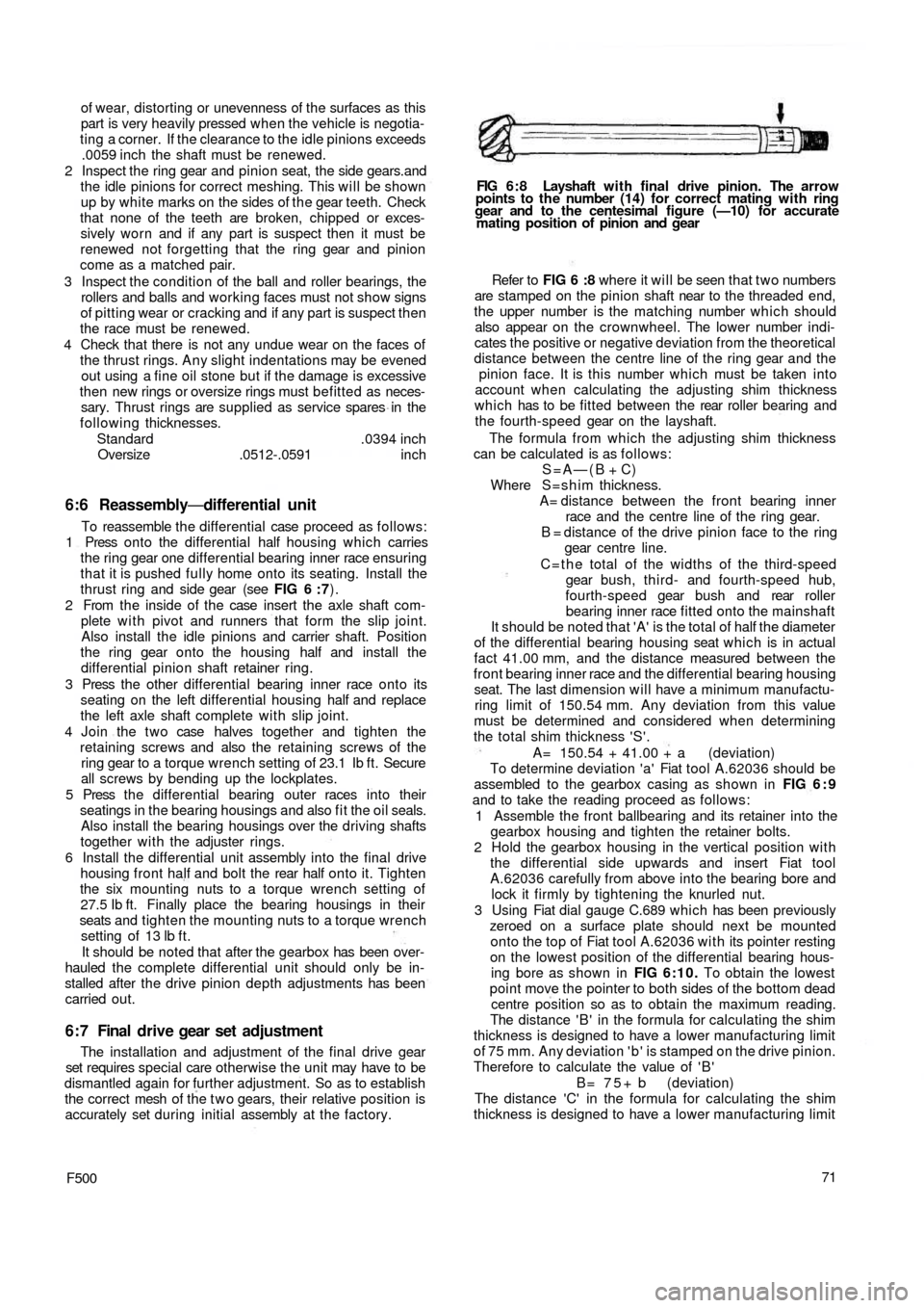
F50071 Refer to FIG 6 :8 where it will be seen that t w o numbers
are stamped on the pinion shaft near to the threaded end,
the upper number is the matching number which should
also appear on the crownwheel. The lower number indi-
cates the positive or negative deviation from the theoretical
distance between the centre line of the ring gear and the
pinion face. It is this number which must be taken into
account when calculating the adjusting shim thickness
which has to be fitted between the rear roller bearing and
the fourth-speed gear on the layshaft.
The formula from which the adjusting shim thickness
can be calculated is as follows:
S=A—(B + C)
Where S=shim thickness.
A= distance between the front bearing inner
race and the centre line of the ring gear.
B = distance of the drive pinion face to the ring
gear centre line.
C = t h e total of the widths of the third-speed
gear bush, third- and fourth-speed hub,
fourth-speed gear bush and rear roller
bearing inner race fitted onto the mainshaft
It should be noted that 'A' is the total of half the diameter
of the differential bearing housing seat which is in actual
fact 41.00 mm, and the distance measured between the
front bearing inner race and the differential bearing housing
seat. The last
dimension will have a minimum manufactu-
ring limit of 150.54 mm. Any deviation from this value
must be determined and considered when determining
the total shim thickness 'S'.
A= 150.54 + 41.00 + a (deviation)
To determine deviation 'a' Fiat tool A.62036 should be
assembled to the gearbox casing as shown in FIG 6 : 9
and to take the reading proceed as follows:
1 Assemble the front ballbearing and its retainer into the
gearbox housing and tighten the retainer bolts.
2 Hold the gearbox housing in the vertical position with
the differential side upwards and insert Fiat tool
A.62036 carefully from above into the bearing bore and
lock it firmly by tightening the knurled nut.
3 Using Fiat dial gauge C.689 which has been previously
zeroed on a surface plate should next be mounted
onto the t o p of Fiat tool A.62036 with its pointer resting
on the lowest position of the differential bearing hous-
ing bore as shown in FIG 6:10. To obtain the lowest
point move the pointer to both sides of the bottom dead
centre position so as to obtain the maximum reading.
The distance ' B ' in the formula for calculating the shim
thickness is designed to have a lower manufacturing limit
of 75 mm. Any deviation ' b ' is stamped on the drive pinion.
Therefore to calculate the value of ' B '
B = 7 5 + b (deviation)
The distance 'C' in the formula for calculating the shim
thickness is designed to have a lower manufacturing limit
FIG 6 : 8 Layshaft w i t h final drive pinion. The arrow
points to the number (14) for correct mating with ring
gear and to the centesimal figure (—10) for accurate
mating position of pinion and gear
Page 71 of 128
although these do not affect the service procedures that
have been previously described.
6:12 Fault diagnosis
(a) Noisy transmission
1 Excessive backlash of gears in mesh due to gear wear
2 Gears, bearings or gear bushings damaged
3 Shafts misaligned or out of centre due to loose mount-
ing nuts
4 Dirt or metal chips in the lubricant
5 Insufficient oil level in transmission case
(b) Transmission jumps out of gear or gear
shifting is irregular
1 Improper shifting
2 Gear shift lever mounting bracket out of adjustment
3 Incorrect assembly or damage of striker rod positioning
balls and springs
4 Striker rod rollers worn or assembled incorrectly
(c) Oil leakage
1 Overfilled transmission case2 Front extension, upper cover and clutch housing nutsloose
3 Speed selector and engagement lever seal at front
extension damaged
4 Faulty bellhousing gasket
5 Gaskets, upper cover-to-case, front extension-to-case,
damaged
6 Damaged axle shaft boot or seal
(d) Transmission shifts hard
1 Defective link of gear shift lever to internal front lever
2 Internal front lever rubber bushing and plates damaged
3 Speed selector and engagement lever control rod
twisted
4 Control rod-to-speed selector and engagement lever
joint damaged
5 Speed selector and engagement lever worn
6 Striker rods binding in casing
7 Sliding sleeves and gears bound in their seats due to
the presence of dirt in splines
8 Improper quality of transmission lubricant
9 Misadjusted clutch linkage and clutch make de-
clutching impossible
78
Page 73 of 128
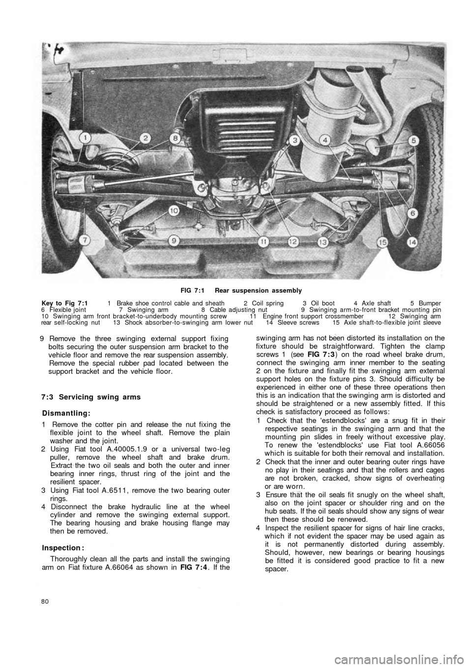
FIG 7 : 1 Rear suspension assembly
Key to Fig 7 : 1 1 Brake shoe control cable and sheath 2 Coil spring 3 Oil boot 4 Axle shaft 5 Bumper
6 Flexible joint 7 Swinging arm 8 Cable adjusting nut 9 Swinging arm-to-front bracket mounting pin
10 Swinging arm front bracket-to-underbody mounting screw 11 Engine front support crossmember 12 Swinging arm
rear self-locking nut 13 Shock absorber-to-swinging arm lower nut 14 Sleeve screws 15 Axle shaft-to-flexible joint sleeve
9 Remove the three swinging external support fixing
bolts securing the outer suspension arm bracket to the
vehicle floor and remove the rear suspension assembly.
Remove the special rubber pad located between the
support bracket and the vehicle floor.
7 : 3 Servicing swing arms
Dismantling:
1 Remove the cotter pin and release the nut fixing the
flexible joint to the wheel shaft. Remove the plain
washer and the joint.
2 Using Fiat tool A.40005.1.9 or a universal two-leg
puller, remove the wheel shaft and brake drum.
Extract the t w o oil seals and both the outer and inner
bearing inner rings, thrust ring of the joint and the
resilient spacer.
3 Using Fiat tool A.6511, remove the t w o bearing outer
rings.
4 Disconnect the brake hydraulic line at the wheel
cylinder and remove the swinging external support.
The bearing housing and brake housing flange may
then be removed.
Inspection :
Thoroughly clean all the parts and install the swinging
arm on Fiat fixture A.66064 as shown in FIG 7 : 4. If the
80
swinging arm has not been distorted its installation on the
fixture should be straightforward. Tighten the clamp
screws 1 (see FIG 7 : 3) on the road wheel brake drum,
connect the swinging arm inner member to the seating
2 on the fixture and finally fit the swinging arm external
support holes on the fixture pins 3. Should difficulty be
experienced in either one of these three operations then
this is an indication that the swinging arm is distorted and
should be straightened or a new assembly fitted. If this
check is satisfactory proceed as follows:
1 Check that the 'estendblocks' are a snug fit in their
respective seatings in the swinging arm and that the
mounting pin slides in freely w it h ou t excessive play.
To renew the 'estendblocks' use Fiat tool A.66056
which is suitable for both their removal and installation.
2 Check that the inner and outer bearing outer rings have
no play in their seatings and that the rollers and cages
are not broken, cracked, show signs of overheating
or are worn.
3 Ensure t h a t the o i l seals f i t snugly on the wheel shaft,
also on the joint spacer or shoulder ring and on the
hub seats. If the oil seals should show any signs of wear
then these should be renewed.
4 Inspect the resilient spacer for signs of hair line cracks,
which if not evident the spacer may be used again as
it is not permanently distorted during assembly.
Should, however, new bearings or bearing housings
be fitted it is considered good practice to fit a new
spacer.
Page 79 of 128
A tolerance of —10'.+ 15' is permitted providing
that the value is the same for both rear wheels. It is
important that both rear wheels are set to the same
angle otherwise uneven tyre wear and adverse handl-
ing conditions will result. When the wheel is parallel to
the centre line of the vehicle the pin of bracket
C.696/3 will be .216 inch apart from the pin of the
front suspension swinging arm.
7 Release the swinging arm outer support to body
mounting screws and position arm in such a way as to
obtain the condition as described in Number 6 above.
After the adjustment has been completed tighten
the outer support mounting screws to a torque wrench
setting of 28.9 to 36.2 Ib/ft. Also tighten the two
swinging arm pin nuts C (see FIG 7 : 7) to a torque
wrench setting of 43.4 to 50.6 Ib/ft. Take off the gauge
C.696 w i t h bracket and support C.696/3, and repeat
the check and adjustment operations on the other
wheel. Care must be taken to ensure that bracket
C.696/3 is reversed from the position previously used.
New 500 type 500D, 110F and 110L sedan and
station wagon:
After the rear suspension has been replaced, check
and, if necessary adjust the rear wheel geometry.
1 Inflate the tyres to the normal operating pressures.
2 Lower the car body so that the rear wheels are set at
90 deg. to the floor. This condition is obtained when
the lowermost portion of the sump is 6.61 inches from
the floor level for the new 500D model or the centre
rear bracket for jacking up the rear of t h e vehicle
8.9 inches from the floor level for the 500 Station
Wagon.
3 With the vehicle set to the above conditions check the
wheel geometry. The wheel plane must converge w i t h
the centre line of the vehicle by an angle of 0 deg. 10'
(—10', +15') toeing in at the front.
4 The wheel plane must be 22.343 ± .059 inches from
the centre line of the vehicle for the 500D model.
Whereas for the 500 Station Wagon the distance must
be 22.264 ± .059 inches.
5 To adjust the rear wheel toe-in adjust the positions of
the mounting screws A and B as shown in FIG 7:7.
86
7:7 Modifications
The new 500 Sedan (110F) and late 500 Station
Wagon are fitted with modified wheels side flexible
joints and rear control arm as shown in FIG 7:13.
Together w i t h these modifications a new design rear
coil spring has been fitted details of which are given in
Technical Data.
7 : 8 Fault diagnosis
(a) Irregular or abnormal tyre wear
1 Incorrect tyre pressure
2 Wheels out of balance
3 Wheels off centre
4 Misadjusted brakes
5 Weak or broken coil springs
6 Excessive load
7 Incorrect wheel alignment
(b) Sag on one wheel
1 Incorrect tyre pressure
2 Weak or broken coil spring
3 Wear of shock absorber causing poor dampening
action
(c) Squeaks, thumps or rattles
1 Wheels out of balance
2 Wheels off centre
3 Misadjusted brakes
4 Weak or broken coil springs or spring seats dislodged
5 Wear of shock absorbers causing poor dampening
action
6 Worn rubber bushings in control arms
7 Poor lubrication of wheel bearings
(d) Pull to one side
1 Incorrect tyre pressure
2 Misadjusted brakes
3 Distorted suspension arm
Page 90 of 128
CHAPTER 9
THE STEERING SYSTEM
9 : 5 Relay lever and support
9 : 6 Steering rods
9 : 7 Front wheel toe-in
9 : 8 Fault diagnosis 9:1 Description
9 : 2 Steering wheel removal and refitting
9 : 3 Steering box removal and refitting
9 : 4 Steering box dismantling and reassembly
9:1 Description
The steering gear fitted to the new 500 range of
vehicles is of the worm screw and sector type with a
steering ratio of 1:13. The steering gearbox is located on
the front lefthand side of the dash wall on the scuttle as
shown in FIG 9:1. The steering gear comprises a pitman
arm and relay lever pivoting on a pin supported on the
body. A central track rod connects the pitman arm to the
relay lever. T w o track rods connect the pitman arm and
relay lever to the knuckle arms.
9:2 Steering wheel removal and refitting
To remove the steering wheel proceed as follows:
1 Disconnect the battery positive terminal clamp and
remove the horn control from the steering wheel.
2 Remove the cable from the push button seating and the
cable insulation sleeve.
3 Using a suitably sized box spanner or Fiat wrench
A.8279 unscrew the steering wheel to shaft nut as
shown in FIG 9:2.
4 Using the palm of the hands against the back of the
steering wheel rim gently tap the steering wheel
forwards so releasing it from the inner shaft.
F50097 5 Reassembly is the reverse procedure to dismantling.
Care should be taken to ensure that the front wheels
are located in the straight ahead position when the
steering wheel is being replaced otherwise the steering
wheel spokes will not be correctly positioned.
9 : 3 Steering box removal and refitting
To remove the steering box from the vehicle proceed
as follows:
1 From inside the vehicle remove the steering column
clamp bolt 6 (see FIG 9 : 3) after flattening the lock-
washer 7.
2 From the underside of the vehicle remove the t w o
tie rod locking nuts from the pitman arm and then using
Fiat tool A.46006 or a suitable t w o leg puller withdraw
the pins from the seats.
3 Remove the three nuts holding the steering box to the
body panel. Ease out the worm screw from the
steering shaft and lift away the steering box.
4 To refit the steering box is the reverse procedure to
dismantling. The steering box to body mounting nuts
should be tightened to a torque wrench setting of
14 Ib/ft to 18 Ib/ft.
Page 120 of 128
CHAPTER 12
THE BODYWORK
12:1
12:2
12:3
12:4
12:5
12:6
12:7Bodywork finish
Interior and chrome cleaning
Door trim and accessories
Door handles and locks
Removing regulator and door glass
Removing windshield glass
Removing rear side windows12:8
12:9
12:10
12:11
12:12
12:13
12:14Removing rear window glass
Front compartment lid
Engine compartment lid
Folding top
Sun roof
Seats
Interior heater
12:1 Bodywork finish
Large scale repairs to body panels are best left to
expert panel beaters. Even small dents can be tricky, as too
much hammering will stretch the metal and make things
worse instead of better. Filling minor dents and scratches
is probably the best method of restoring the surface. The
touching up of paintwork is well within the powers of
most car owners, particularly as self-spraying cans of
paint in the correct colours are now readily available. It
must be remembered, however, that paint changes colour
w i t h age and it is better to spray a whole wing rather than
try to touch up a small area.
Before spraying it is essential to remove all traces of
wax polish with white spirit. More drastic treatment is
required if silicone polishes have been applied. Use a
primer surfacer or paste stopper according to the amount
of filling required, and when it is dry, rub it down with
400 grade Wet or Dry paper until the surface is smooth
and flush with the surrounding area. Spend time on
getting the best finish as this will control the final effect.
Apply the retouching paint, keeping it wet in the centre
and light and dry round the edges. After a few hours of
drying, use a cutting compound to remove the dry spray
and finish with liquid polish.
F500127
12:2 Interior and chrome cleaning
The cloth upholstery of the seating and the rear
compartment lining must be regularly cleaned to ensure
long life and preserve its attractive appearance. Any dust
or dirt that is blown into the car will settle on the uphol-
stery and will tend to wear the cloth causing an unsightly
appearance. It is recommended that the dust is wiped off
using either a vacuum cleaner or a stiff brush. To remove
ordinary soiling of the upholstery cloth proceed as
follows:
1 Using luke warm water and a neutral soap and a piece
of clean cloth wipe over the upholstery in the direction
of the nap.
2 Repeat the operation using a clean damp cloth and
warm water but no soap.
3 Allow the upholstery cloth to dry, use a stiff brush
against the direction of the upholstery nap to restore
its original fluffy look.
To obtain best results, any stains must be removed as
soon as possible otherwise as time passes they will
become more difficult, if not impossible to remove.
Certain stains require specific solvents and the instruc-
tions must be strictly adhered to.
Page 127 of 128
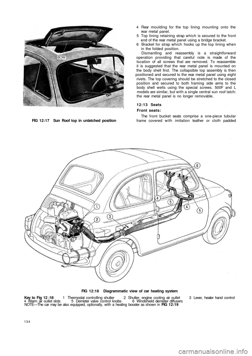
BOW
FIG 12:17 Sun Roof top in unlatched position
FIG 12:18 Diagrammatic view of car heating system
Key to Fig 12 :18 1 Thermostat controlling shutter 2 Shutter, engine cooling air outlet 3 Lever, heater hand control
4 Warm air outlet slots 5 Demister valve control knobs 6 Windshield demister diffusers
NOTE—The car may be also equipped, optionally, with a heating booster as shown in FIG 12:19
134
4 Rear moulding for the top lining mounting onto the
rear metal panel.
5 Top lining retaining strap which is secured to the front
end of t h e rear metal panel using a bridge bracket.
6 Bracket for strap which hooks up the top lining when
in the folded position.
Dismantling and reassembly is a straightforward
operation providing that careful note is made of the
location of all screws that are removed. To reassemble
it is suggested that the rear metal panel is mounted on
the body shell first. The collapsible top assembly is then
positioned and secured to the rear metal panel using eight
rivets. The top covering should be stretched to the closed
position and secured to both framing side arms to t h e
body shell wells using the special screws. 500F and L
models are similar, but with a single central sun roof latch:
t h e rear metal panel is no longer removable.
12:13 Seats
Front seats:
The front bucket seats comprise a one-piece tubular
frame covered with imitation leather or cloth padded
Page 128 of 128
cushion and back rest. A number of rubber straps are
hooked across the frame under the cushion and in a
sheath covering on the seat back.
The bottom of the front seat frame ends are provided
with sliding guides which run in guide rails attached to
the floor. The sliding guides are pivoted on the frame
tubes to allow for forward tilting of the seats giving better
access to the rear compartment. Two rubber pads
provide cushioning of the seat frame on the guide rails
as shown in FIG 12:11. The control lever for seat
adjustment is fitted in the frame righthand tube to permit
unlocking of the seats so that they may be adjusted to
individual drivers requirements.
Rear seats (Sedan):
The rear seat comprises of a foam rubber cushion and
back. The seat back is cemented to the rear floor and
body shell bulkhead. The rear seat lining is of fabric and
imitation leather. The seat lining is held in place by four
self-tapping screws, t w o of which secure the floor below
the back window and two the lining at the base of t h e
back rest. Included with the seat assembly is a masonite
floor which is fitted below the rear window.
Rear Seat (Station Wagon):
The rear seat back rest is pivoted at the base of its
frame so that it can be folded down to form a load plat-
form surface. In the upright position it is retained in place
by t w o brackets mounted on either side of the body below
the side
windows.
12:14 Interior heater
Description:
Interior heating is accomplished by recirculation of
warm air from the engine cooling system through engine
cowling. Referring to FIG 12:18 a hose conveys warmed
air from the engine cowling to the centre tunnel floor
where warm air flows out through two slots being cut on
the windshield delivery hoses. Air admission can be
adjusted by turning the control lever to the right which
operates the tunnel throttle valve at the rear seat.
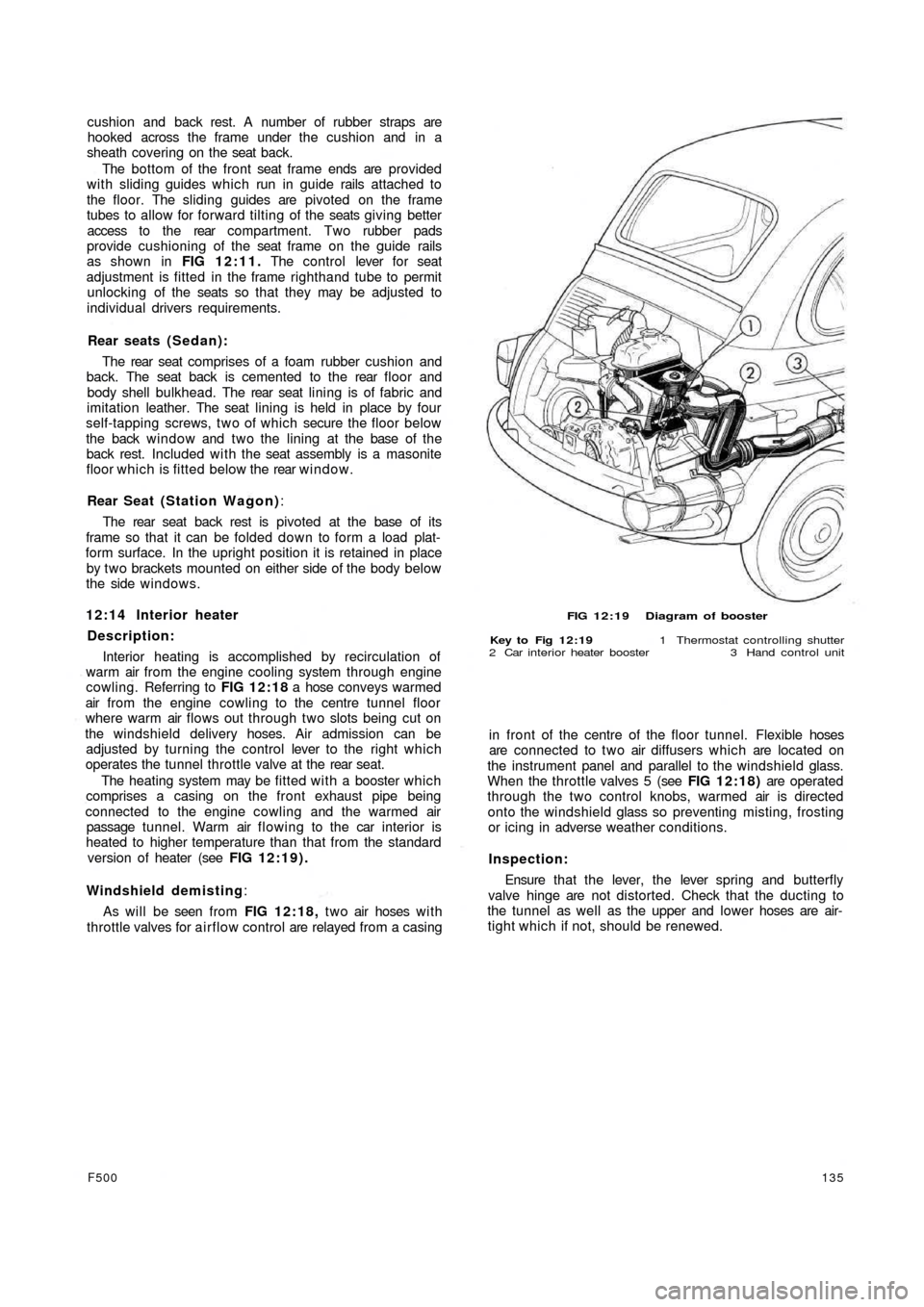
The heating system may be fitted with a booster which
comprises a casing on the front exhaust pipe being
connected to the engine cowling and the warmed air
passage tunnel. Warm air flowing to the car interior is
heated to higher temperature than that from the standard
version of heater (see FIG 12:19).
Windshield demisting:
As will be seen from FIG 12:18, t w o air hoses w i t h
throttle valves for airflow control are relayed from a casing
F500135
FIG 12:19 Diagram of booster
Key to Fig 12:19 1 Thermostat controlling shutter
2 Car interior heater booster 3 Hand control unit
in front of the centre of the floor tunnel. Flexible hoses
are connected to two air diffusers which are located on
the instrument panel and parallel to the windshield glass.
When the throttle valves 5 (see FIG 12:18) are operated
through the two control knobs, warmed air is directed
onto the windshield glass so preventing misting, frosting
or icing in adverse weather conditions.
Inspection:
Ensure that t h e lever, the lever spring and butterfly
valve hinge are not distorted. Check that the ducting to
the tunnel as well as the upper and lower hoses are air-
tight which if not, should be renewed.