ECU FIAT 500 1961 1.G Owner's Manual
[x] Cancel search | Manufacturer: FIAT, Model Year: 1961, Model line: 500, Model: FIAT 500 1961 1.GPages: 128, PDF Size: 9.01 MB
Page 60 of 128
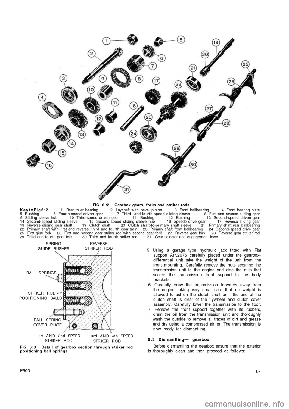
FIG 6 :2 Gearbox gears, forks and striker rods
KeytoFig6:2 1 Rear roller bearing 2 Layshaft with bevel pinion 3 Front ballbearing 4 Front bearing plate
5 Bushing 6 Fourth-speed driven gear 7 Third- and fourth-speed sliding sleeve 8 First and reverse sliding gear
9 Sliding sleeve hub 10 Third-speed driven gear 11 Bushing 12 Bushing 13 Second-speed driven gear
14 Second-speed sliding sleeve 15 Second-speed sliding sleeve hub 16 Speedo drive gear 17 Reverse sliding gear
18 Reverse sliding gear shaft 19 Clutch shaft 20 Clutch shaft-to-primary shaft sleeve 21 Primary shaft rear ballbearing
22 Primary shaft with first and reverse, third and fourth gear train 23 Primary shaft front ballbearing 24 Second-speed drive gear
25 First gear fork 26 First and second gear striker rod with second gear fork 27 Reverse gear fork 28 Reverse gear striker rod
29 Third and fourth gear fork 30 Third and fourth striker rod 31 Gear selector and engagement lever
SPRING
GUIDE BUSHES
REVERSESTRIKER R O D
BALL SPRINGS
POSITIONING BALLS STRIKER R O D
BALL SPRING
COVER PLATE
1st A N D 2 n d SPEED
STRIKER R O D3 r d A N D 4 t h SPEED
STRIKER R O D
FIG 6 : 3 Detail of gearbox section through striker rod
positioning ball springs
F50067 5 Using a garage type hydraulic jack fitted with Fiat
support Arr.2076 carefully placed under the gearbox-
differential unit take the weight of the unit from the
front mounting. Carefully remove the nuts securing the
transmission unit to the engine and also the nuts that
secure the transmission front support to the body
brackets.
6 Carefully draw the transmission forwards away from
the engine taking very great care that no weight is
allowed to act on the clutch shaft until the end of the
clutch shaft is clear of the flywheel and clutch cover
assembly. Carefully lower the transmission to the floor.
7 Remove the front support together with its rubbers,
drain the oil from the transmission unit and thoroughly
wash the outside to remove all traces of dirt and grease
and dry using a compressed air jet. The transmission is
now ready for dismantling.
6:3 Dismantling— gearbox
Before dismantling the gearbox ensure that the exterior
is thoroughly clean and then proceed as follows:
Page 63 of 128
3 Check the layshaft and the primary shaft between
centres and using a dial gauge ensure that there is no
distortion. The out of true reading for bearing seats
should be less than .0008 inch. Inspect the splines and
ensure that the side and outerfaces are not indented.
Replace if there are signs of wear. Also inspect the
reverse shaft to ensure that it is perfectly smooth and
not showing signs of pitting or partial seizure.
4 Carefully inspect all gear teeth for signs of excessive
wear or damage. The contact faces must be smooth and
show no signs of indentation marks. Also check that
the backlash between the gears, when correctly
mounted on the surface plate is not greater than .0039
inch. The maximum wear limit is .0079 inch. Check that
the quick engagement front teeth of the second-, third-
and fourth-speed gears are not damaged or excessively
worn. Renew if there are signs of gearchange lever
misuse.
5 Inspect the sliding sleeves and the relevent hubs, ensure
that all the working surfaces are perfectly smooth. The
clearance between the mating parts should not be
greater than .0059 inch. Also inspect the meshing teeth
and ensure that they are in good condition.
6 Check that the gear shifting selector forks are not dis-
torted and that the striker rods freely slide in their seats
in the gearbox casing.
7 Carefully inspect that all the oil seals are in perfect con-
dition and if there is any doubt they should be renewed.
8 Inspect the striker rod locking balls and the safety rollers
and ensure that they slide freely in their seatings. Also
check the ball load spring efficiency and if this shows
signs of weakness then it should be renewed. Any
faults with these items will cause difficulty in engaging
gears or autodisengagement during engine acceleration.
6 : 4 Reassembly—gearbox
To reassemble the components to the gearbox ensure
that all components are thoroughly clean and then pro-
ceed as follows:
1 Press t h e pinion rear roller bearing onto the layshaft.
Install the layshaft in the casing, and at the same time
fit the adjustment shim, the fourth-speed driven gear
together w i t h its bush, the sleeve and hub for third and
fourth gear engagement, the first-speed and reverse
driven gear and the third-speed driven gear with its
hub.
2 Install the front layshaft ballbearing securing the
bearing retainment plate w i t h the screws and finally
lock the screws in position.
3 Insert the primary shaft together with the first, third
and fourth driving gear train in the gearbox housing
and slide t h e rear bearing onto the shaft. Push the
input shaft forward to enable the clutch shaft coupling
to be inserted in t h e rear and to be pulled up the
primary shaft by means of the pin. Do not forget the
retaining ring.
4 Slide the primary shaft backwards so pushing the rear
bearing into its bore. Refit the front bearing onto the
primary shaft.
5 On the layshaft insert the second-speed driven shaft
and bush, the second gear sliding dog sleeve and the
hub. Also insert the second-speed striker rod and the
first-speed fork. Do not forget to fit the safety roller
into its seating.
70
6 Slide the second-speed driving gear onto the primary
shaft. Place the engagement fork on the third- and
fourth-speed engagement sliding sleeve, and insert
the striker rod, lock the relevent fork and fit the safety
roller.
7 Insert the third safety roller and install the reverse shaft
and insert the reverse gear cluster onto it and secure
the shaft by tightening its block bolt. Install the reverse
striker rod w i t h its relevent fork.
8 Now refit the speedometer drive worm gear onto the
layshraft. Tighten the nuts on the primary shaft and the
layshaft, not forgetting to interpose the plain washer
between the speedometer driving worm and the nut,
to a torque wrench setting of 1 8.1 Ib ft to 25.3 Ib ft
(primary shaft) and 28.9 to 36.2 Ib ft (layshaft). It is
recommended that the input shaft and layshaft are
locked together by engaging t w o gears at the same
time. Finally, fit the splitpins.
9 Lock the shifter forks onto their shafts by tightening
their respective bolts and bend up the special locking
plates. Install the three positioning balls and relevant
springs into their bores and refit the cover plate.
10 Install the casing cover together with its relevant
gasket. This will enable correct positioning of the shift
shaft lever so that it engages in the outer ends of the
shifter shafts protruding from the gearbox casing.
11 Install the speedometer drive support on the gearbox
casing and refit the upper gearbox cover.
For subsequent differential operations and adjustments
see Sections 6:6.
6:5 Dismantling—differential and final drive
For the removal of the differential and final drive unit
from the gearbox refer to Section 6:3. To dismantle the
differential assembly
proceed as follows:
1 Remove the retaining ring 2 (see FIG 6 : 7) retaining
the splined sleeve 4 and slide the sleeve off the drive
shaft.
2 Remove t h e retaining covers 7 and the oil boots all
together with the bushes and seals, adjuster ring lock
rings 13, adjuster rings housing 14, and bearing
adjuster and roller bearing outer races.
3 Separate the differential housing halves by unscrewing
and removing the six bolts that keep both the halves and
the crownwheel together. It is advisable to mark the
respective components to ensure correct matching
upon reassembly.
4 Remove the differential pinion shaft retainer ring, also
the differential pinions 10 by removing the shaft and
withdrawing the two axle shafts 1.
5 Remove the differential side gears 6 and relevent thrust
rings 8.
6 Using a press remove the differential bearing inner
races from their seats on the carrier halves.
7 Thoroughly clean all parts and dry using a compressed
air jet.
Inspection:
The components of the differential unit must be
thoroughly inspected for correct operation and to deter-
mine the presence of any wear, damage or other irregulari-
ties. To check the items concerned proceed as follows:
1 Check thoroughly the idle pinion carrier shaft for signs
Page 64 of 128
of wear, distorting or unevenness of the surfaces as this
part is very heavily pressed when the vehicle is negotia-
ting a corner. If the clearance to the idle pinions exceeds
.0059 inch the shaft must be renewed.
2 Inspect the ring gear and pinion seat, the side gears.and
the idle pinions for correct meshing. This will be shown
up by white marks on the sides of the gear teeth. Check
that none of the teeth are broken, chipped or exces-
sively worn and if any part is suspect then it must be
renewed not forgetting that the ring gear and pinion
come as a matched pair.
3 Inspect the condition of the ball and roller bearings, the
rollers and balls and working faces must not show signs
of pitting wear or cracking and if any part is suspect then
the race must be renewed.
4 Check that there is not any undue wear on the faces of
the thrust rings. Any slight indentations may be evened
out using a fine oil stone but if the damage is excessive
then new rings or oversize rings must befitted as neces-
sary. Thrust rings are supplied as service spares in the
following thicknesses.
Standard .0394 inch
Oversize .0512-.0591 inch
6:6 Reassembly—differential unit
To reassemble the differential case proceed as follows:
1 Press onto the differential half housing which carries
the ring gear one differential bearing inner race ensuring
that it is pushed fully home onto its seating. Install the
thrust ring and side gear (see FIG 6 : 7).
2 From t h e inside of the case insert the axle shaft com-
plete with pivot and runners that form the slip joint.
Also install the idle pinions and carrier shaft. Position
the ring gear onto the housing half and install the
differential pinion shaft retainer ring.
3 Press the other differential bearing inner race onto its
seating on the left differential housing half and replace
the left axle shaft complete with slip joint.
4 J o i n the t w o case halves together and tighten the
retaining screws and also the retaining screws of the
ring gear to a torque wrench setting of 23.1 Ib ft. Secure
all screws by bending up the lockplates.
5 Press t h e differential bearing outer races into their
seatings in the bearing housings and also f i t the o i l seals.
Also install the bearing housings over the driving shafts
together with the adjuster rings.
6 Install the differential unit assembly into the final drive
housing front half and bolt the rear
half onto it. Tighten
the six mounting nuts to a torque wrench setting of
27.5 Ib ft. Finally place the bearing housings in their
seats and tighten the mounting nuts to a torque wrench
setting of 13 lb ft.
It should be noted that after the gearbox has been over-
hauled the complete differential unit should only be in-
stalled after the drive pinion depth adjustments has been
carried out.
6 : 7 Final drive gear set adjustment
The installation and adjustment of the final drive gear
set requires special care otherwise the unit may have to be
dismantled again for further adjustment. So as to establish
the correct mesh of the t w o gears, their relative position is
accurately set during initial assembly at the factory.
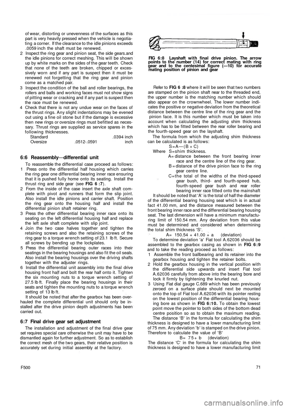
F50071 Refer to FIG 6 :8 where it will be seen that t w o numbers
are stamped on the pinion shaft near to the threaded end,
the upper number is the matching number which should
also appear on the crownwheel. The lower number indi-
cates the positive or negative deviation from the theoretical
distance between the centre line of the ring gear and the
pinion face. It is this number which must be taken into
account when calculating the adjusting shim thickness
which has to be fitted between the rear roller bearing and
the fourth-speed gear on the layshaft.
The formula from which the adjusting shim thickness
can be calculated is as follows:
S=A—(B + C)
Where S=shim thickness.
A= distance between the front bearing inner
race and the centre line of the ring gear.
B = distance of the drive pinion face to the ring
gear centre line.
C = t h e total of the widths of the third-speed
gear bush, third- and fourth-speed hub,
fourth-speed gear bush and rear roller
bearing inner race fitted onto the mainshaft
It should be noted that 'A' is the total of half the diameter
of the differential bearing housing seat which is in actual
fact 41.00 mm, and the distance measured between the
front bearing inner race and the differential bearing housing
seat. The last
dimension will have a minimum manufactu-
ring limit of 150.54 mm. Any deviation from this value
must be determined and considered when determining
the total shim thickness 'S'.
A= 150.54 + 41.00 + a (deviation)
To determine deviation 'a' Fiat tool A.62036 should be
assembled to the gearbox casing as shown in FIG 6 : 9
and to take the reading proceed as follows:
1 Assemble the front ballbearing and its retainer into the
gearbox housing and tighten the retainer bolts.
2 Hold the gearbox housing in the vertical position with
the differential side upwards and insert Fiat tool
A.62036 carefully from above into the bearing bore and
lock it firmly by tightening the knurled nut.
3 Using Fiat dial gauge C.689 which has been previously
zeroed on a surface plate should next be mounted
onto the t o p of Fiat tool A.62036 with its pointer resting
on the lowest position of the differential bearing hous-
ing bore as shown in FIG 6:10. To obtain the lowest
point move the pointer to both sides of the bottom dead
centre position so as to obtain the maximum reading.
The distance ' B ' in the formula for calculating the shim
thickness is designed to have a lower manufacturing limit
of 75 mm. Any deviation ' b ' is stamped on the drive pinion.
Therefore to calculate the value of ' B '
B = 7 5 + b (deviation)
The distance 'C' in the formula for calculating the shim
thickness is designed to have a lower manufacturing limit
FIG 6 : 8 Layshaft w i t h final drive pinion. The arrow
points to the number (14) for correct mating with ring
gear and to the centesimal figure (—10) for accurate
mating position of pinion and gear
Page 67 of 128
TOOL A 62039
TOOLA. 62040 PIN WRENCH A. 52022
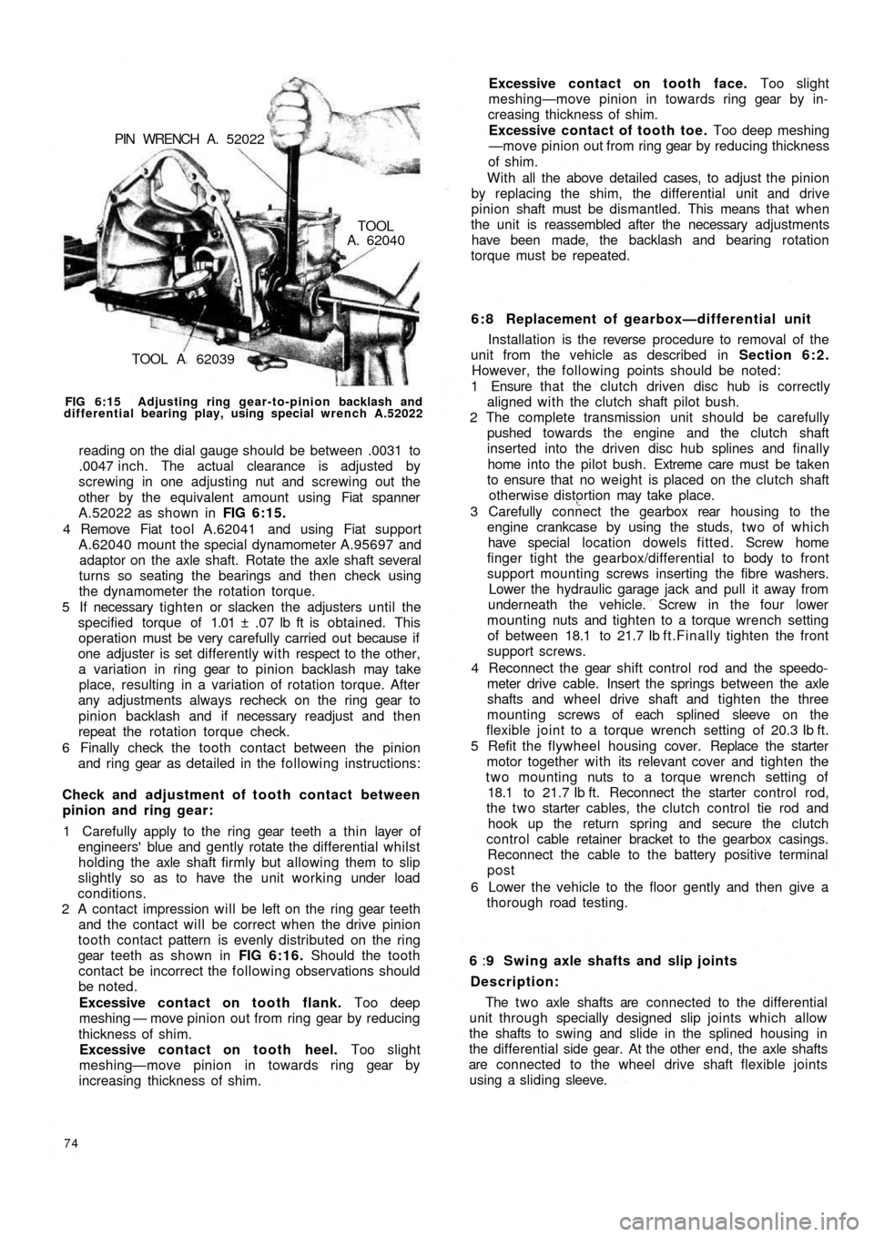
FIG 6:15 Adjusting ring gear-to-pinion backlash and
differential bearing play, using special wrench A.52022
reading on the dial gauge should be between .0031 to
.0047 inch. The actual clearance is adjusted by
screwing in one adjusting nut and screwing out the
other by the equivalent amount using Fiat spanner
A.52022 as shown in FIG 6:15.
4 Remove Fiat tool A.62041 and using Fiat support
A.62040 mount the special dynamometer A.95697 and
adaptor on the axle shaft. Rotate the axle shaft several
turns so seating the bearings and then check using
the dynamometer the rotation torque.
5 If necessary tighten or slacken the adjusters until the
specified torque of 1.01 ± .07 lb ft is obtained. This
operation must be very carefully carried out because if
one adjuster is set differently with respect to the other,
a variation in ring gear to pinion backlash may take
place, resulting in a variation of rotation torque. After
any adjustments always recheck on the ring gear to
pinion backlash and if necessary readjust and then
repeat the rotation torque check.
6 Finally check the tooth contact between the pinion
and ring gear as detailed in the following instructions:
Check and adjustment of tooth contact between
pinion and ring gear:
1 Carefully apply to the ring gear teeth a thin layer of
engineers' blue and gently rotate the differential whilst
holding the axle shaft firmly but allowing them to slip
slightly so as to have the unit working under load
conditions.
2 A contact impression will be left on the ring gear teeth
and the contact will be correct when the drive pinion
tooth contact pattern is evenly distributed on the ring
gear teeth as shown in FIG 6:16. Should the tooth
contact be incorrect the following observations should
be noted.
Excessive contact on tooth flank. Too deep
meshing — move pinion out from ring gear by reducing
thickness of shim.
Excessive contact on tooth heel. Too slight
meshing—move pinion in towards ring gear by
increasing thickness of shim.
74
6 : 8 Replacement of gearbox—differential unit
Installation is the reverse procedure to removal of the
unit from the vehicle as described in Section 6:2.
However, the following points should be noted:
1 Ensure that the clutch driven disc hub is correctly
aligned with the clutch shaft pilot bush.
2 The complete transmission unit should be carefully
pushed towards the engine and the clutch shaft
inserted into the driven disc hub splines and finally
home into the pilot bush. Extreme care must be taken
to ensure that no weight is placed on the clutch shaft
otherwise distortion may take place.
3 Carefully connect the gearbox rear housing to the
engine crankcase by using the studs, t w o of which
have special location dowels fitted. Screw home
finger tight the gearbox/differential to body to front
support mounting screws inserting the fibre washers.
Lower the hydraulic garage jack and pull it away from
underneath the vehicle. Screw in the four lower
mounting nuts and tighten to a torque wrench setting
of between 18.1 to 21.7 Ib f t.Finally tighten the front
support screws.
4 Reconnect the gear shift control rod and the speedo-
meter drive cable. Insert the springs between the axle
shafts and wheel drive shaft and tighten the
three
mounting screws of each splined sleeve on the
flexible joint to a torque wrench setting of 20.3 Ib ft.
5 Refit the flywheel housing cover. Replace the starter
motor together with its relevant cover and tighten the
two mounting nuts to a torque wrench setting of
18.1 to 21.7 Ib ft. Reconnect the starter control rod,
the t w o starter cables, the clutch control tie rod and
hook up the return spring and secure the clutch
control cable retainer bracket to the gearbox casings.
Reconnect the cable to the battery positive terminal
post
6 Lower the vehicle to the floor gently and then give a
thorough road testing.
6 :9 Swing axle shafts and slip joints
Description:
The t w o axle shafts are connected to the differential
unit through specially designed slip joints which allow
the shafts to swing and slide in the splined housing in
the differential side gear. At the other end, the axle shafts
are connected to the wheel drive shaft flexible joints
using a sliding sleeve. Excessive contact on tooth face. Too slight
meshing—move pinion in towards ring gear by in-
creasing thickness of shim.
Excessive contact of tooth toe. Too deep meshing
—move pinion out from ring gear by reducing thickness
of shim.
With all the above detailed cases, to adjust the pinion
by replacing the shim, the differential unit and drive
pinion shaft must be dismantled. This means that when
the unit is reassembled after the necessary adjustments
have been made, the backlash and bearing rotation
torque must be repeated.
Page 72 of 128
CHAPTER 7
REAR SUSPENSION AND WHEELS
7:1
7:2
7:3
7:4Description
Removal of rear suspension assembly
Servicing swinging arms
Coil springs
7:1 Description
The rear wheels are independently sprung by means of
coil springs and V-shaped swinging arms acting on coil
springs and telescopic double acting hydraulic shock
absorbers. The swinging arms are m o u n t e d at their inner
ends on 'estendblocks', the coil spring is fitted at the outer
end of the swinging arm. At the wheel end of the suspen-
sion arm is attached a steel pressing to which the brake
backplate and wheel bearing housing are bolted so
forming a swinging unit to which is attached the road
wheel.
The inner pivots are so located vertical wheel move-
ments do not influence the drive shaft length which
means that there is no need to fit a splined joint at the
wheel end. Two taper roller bearings which are separated
by a specially designed collapsible spacer are located in
the rear wheel bearing housing and this carries the axle
shaft. The outer end of the axle shaft is flanged and it
is to this flange that the brake drum is bolted. The splined
inner end carries a rubber cushioned coupling to which
the drive shaft flange is attached.
7 : 2 Removal of rear suspension assembly
1 Jack-up the vehicle and place on firmly based stands.
Remove the road wheel on the side from which the
suspension unit is to be removed.
F50079 7:5
7:6
7:7
7:8Installation of rear suspension assembly
Checking and adjusting rear wheel toe-in
Modifications
Fault diagnosis
2 Using a garage hydraulic jack support the swinging
arm to facilitate the removal of the upper shock
absorber mounting nut which is located inside the
vehicle on the floor. To gain access to the nut remove
the rear wheel housing linings.
3 Unhook the parking brake shoe control lever return
spring.
4 Remove the three screws securing the drive shaft
flange to the flexible coupling. Pull back the sleeve and
remove the inner spring.
5 Remove the brake fluid reservoir cap, remove the filter
and plug the delivery hole in the brake f l u i d reservoir
and disconnect the flexible brake pipe from the
bracket on the body floor.
6 Disconnect the parking brake control tie rod by first
removing the cotter pin and removing the cable eye
from the pin on the shoe control lever. Release the
cable adjustment nuts and free the cable from the
fairlead on the swinging arm.
7 Using the hydraulic jack carefully lower the swinging
arm, fully retract the shock absorber by pushing in the
outer cylinder and carefully pull out the coil spring
together with its mounting rubber rings.
8 Remove the self-locking nut securing the swinging
arm to the internal support welded on the floor.
Extract the mounting pin and note the number and
arrangement of shims between the bushings and the
bracket. This will facilitate reassembly.
Page 73 of 128
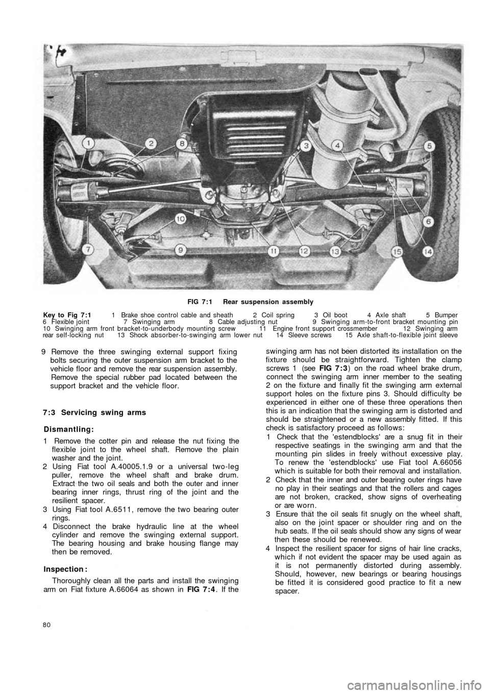
FIG 7 : 1 Rear suspension assembly
Key to Fig 7 : 1 1 Brake shoe control cable and sheath 2 Coil spring 3 Oil boot 4 Axle shaft 5 Bumper
6 Flexible joint 7 Swinging arm 8 Cable adjusting nut 9 Swinging arm-to-front bracket mounting pin
10 Swinging arm front bracket-to-underbody mounting screw 11 Engine front support crossmember 12 Swinging arm
rear self-locking nut 13 Shock absorber-to-swinging arm lower nut 14 Sleeve screws 15 Axle shaft-to-flexible joint sleeve
9 Remove the three swinging external support fixing
bolts securing the outer suspension arm bracket to the
vehicle floor and remove the rear suspension assembly.
Remove the special rubber pad located between the
support bracket and the vehicle floor.
7 : 3 Servicing swing arms
Dismantling:
1 Remove the cotter pin and release the nut fixing the
flexible joint to the wheel shaft. Remove the plain
washer and the joint.
2 Using Fiat tool A.40005.1.9 or a universal two-leg
puller, remove the wheel shaft and brake drum.
Extract the t w o oil seals and both the outer and inner
bearing inner rings, thrust ring of the joint and the
resilient spacer.
3 Using Fiat tool A.6511, remove the t w o bearing outer
rings.
4 Disconnect the brake hydraulic line at the wheel
cylinder and remove the swinging external support.
The bearing housing and brake housing flange may
then be removed.
Inspection :
Thoroughly clean all the parts and install the swinging
arm on Fiat fixture A.66064 as shown in FIG 7 : 4. If the
80
swinging arm has not been distorted its installation on the
fixture should be straightforward. Tighten the clamp
screws 1 (see FIG 7 : 3) on the road wheel brake drum,
connect the swinging arm inner member to the seating
2 on the fixture and finally fit the swinging arm external
support holes on the fixture pins 3. Should difficulty be
experienced in either one of these three operations then
this is an indication that the swinging arm is distorted and
should be straightened or a new assembly fitted. If this
check is satisfactory proceed as follows:
1 Check that the 'estendblocks' are a snug fit in their
respective seatings in the swinging arm and that the
mounting pin slides in freely w it h ou t excessive play.
To renew the 'estendblocks' use Fiat tool A.66056
which is suitable for both their removal and installation.
2 Check that the inner and outer bearing outer rings have
no play in their seatings and that the rollers and cages
are not broken, cracked, show signs of overheating
or are worn.
3 Ensure t h a t the o i l seals f i t snugly on the wheel shaft,
also on the joint spacer or shoulder ring and on the
hub seats. If the oil seals should show any signs of wear
then these should be renewed.
4 Inspect the resilient spacer for signs of hair line cracks,
which if not evident the spacer may be used again as
it is not permanently distorted during assembly.
Should, however, new bearings or bearing housings
be fitted it is considered good practice to fit a new
spacer.
Page 75 of 128
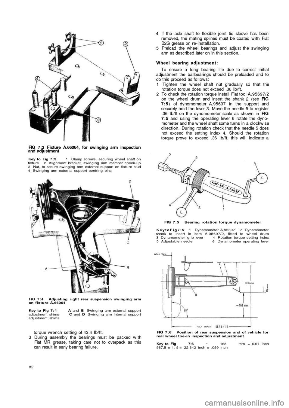
FIG 7 : 3 Fixture A.66064, for swinging arm inspection
and adjustment
Key to Fig 7 : 3 1 Clamp screws, securing wheel shaft on
fixture 2 Alignment bracket, swinging arm member check-up
3 Nut, to secure swinging arm external support on fixture stud
4 Swinging arm external support centring pins
AB C
D
FIG 7 : 4 Adjusting right rear suspension swinging arm
on fixture A.66064
Key to Fig 7 : 4 A and B Swinging arm external support
adjustment shims C and D Swinging arm internal support
adjustment shims
torque wrench setting of 43.4 Ib/ft.
3 During assembly the bearings must be packed w i t h
Fiat MR grease, taking care not to overpack as this
can result in early bearing failure.
82
4 If the axle shaft to flexible joint tie sleeve has been
removed, the mating splines must be coated w i t h Fiat
B2G grease on re-installation.
5 Preload the wheel bearings and adjust the swinging
arm as described later on in this section.
Wheel bearing adjustment:
To ensure a long bearing life due to correct initial
adjustment the ballbearings should be preloaded and to
do this proceed as follows:
1 Tighten the wheel shaft nut gradually so that the
rotation torque does not exceed .36 Ib/ft.
2 To check the rotation torque install Fiat tool A.95697/2
on the wheel drum and insert the shank 2 (see FIG
7:5) of dynomometer A.95697 in the support and
securely hold the lever 3. Move the needle 5 to register
.36 Ib/ft on the dynomometer scale as shown in FIG
7:5 and using the operating lever 6 rotate the dyno-
mometer and the wheel shaft some turns in a clockwise
direction. During rotation check that the needle 5 does
not exceed the setting index 4. Should the rotation
torque prove to exceed .36 Ib/ft, this will indicate a
4
3
1
6
5 2
FIG 7 : 5 Bearing rotation torque dynamometer
KeytoFig7:5 1 Dynamometer A.95697 2 Dynamometer
shank to insert in item A.95697/2, fitted to wheel drum
3 Dynamometer grip lever 4 Rotation torque setting index
5 Adjustable needle 6 Dynamometer operating lever
Oil Sump Wheel Plane
HALF TRACK
FIG 7 : 6 Position of rear suspension and of vehicle for
rear wheel toe-in inspection and adjustment
Key to Fig 7:6 ~ 168 mm = 6.61 inch
567,5 ±1,5= 22.342 inch ± .059 inch
Page 76 of 128
high bearing preload. To reset remove the wheel shaft
and fit a new resilient spacer. Repeat the rotation
torque test.
Swinging arm adjustment:
To adjust the swinging arm use Fiat fixture A.66064 as
shown in FIG 7 : 3 and proceed as follows:
1 At points A and B as indicated in FIG 7 : 4 between the
'estendblock' and the swinging arm to body front
mounting bracket fit three shims on each side. To
ensure that the shims are correctly centred use Fiat
alignment bar A.66057.
2 Whilst removing the alignment bar, carefully slip in the
mounting pin and screw on the nut. Once the rear
wheel geometry adjustment has been completed this
nut should be tightened to a torque wrench setting
of 43.4 to 50.6 Ib ft.
3 At points C and D (see FIG 7 : 4) , insert the number of
shims required to fill in the gap between the 'estend-
block' and the two fixture shoulders. Having deter-
mined the number of shims required both at locations
C and D, these must later be fitted between the
'estendblock' and the shoulders on the swinging arm
to body mounting bracket.
7 : 4 Coil springs
The coil springs should be thoroughly cleaned and all
traces of rust removed. Inspect the spring coils for hair
line cracks, which if evident, a new pair of springs must
be fitted to ensure correct vehicle height and stability.
Check the free
height and the height under loading of
the coil springs and these must correspond to the figures
quoted in Technical Data.
7:5 Installation of rear suspension assembly
To replace the rear suspension assembly proceed as
follows:
1 Insert the swinging arm inner end in the mounting
bracket which is welded onto the body floor. Place
between the 'estendblock' and bracket the number of
adjustment shims as previously determined using Fiat
fixture A.66064 as shown in FIG 7 : 4. Insert the Fiat
alignment bar A.66057 through 'estendblock' and
shims, aligning them with the holes in the mounting
bracket. Firmly hold the entire assembly using a garage
hydraulic jack if necessary, and carefully remove the
alignment bar and at the same time ease in t h e
mounting pin. Secure the nut which once the rear
wheels geometry has been checked must be tightened
to a torque wrench setting of 43.4 to 50.6 Ib/ft.
2 Screw in finger tight the three swinging arm external
bracket to body floor mounting screws together w i t h
the plain and spring washers. The screws will have to
be tightened to a torque wrench setting of 28.9 to
36.2 Ib/ft once the rear wheel geometry has been
adjusted.
3 Carefully insert the coil spring, lower insulator ring
onto the swinging arm, insert the spring on the shock
absorber which should be previously secured to the
arm and position the spring onto its seat on the arm.
Place the upper insulator ring onto the spring, raise the
suspension assembly using a garage hydraulic jack and
insert the spring onto its seating under the body floor.
F50083 4 Ensure that the shock absorber to floor rubber ring has
been correctly fitted and extend the shock absorber
until its upper mounting pin protrudes into the vehicle
through the hump in the floor panel. Secure the shock
absorber by its mounting nut and lockwasher having
first inserted the rubber ring and plain washer.
5 Refit the rear wheel housing in place, reconnect the
brake line to the connection on body floor and remove
the plug from the output hole in the brake fluid
reservoir. Bleed the hydraulic brake system as
described in Chapter 10.
Key to Fig 7:8 k Distance of centre rear bracket, for
jacking up the vehicle, from floor level (8.90 inch)
Half-track = 22.264 inch ±.059 inch
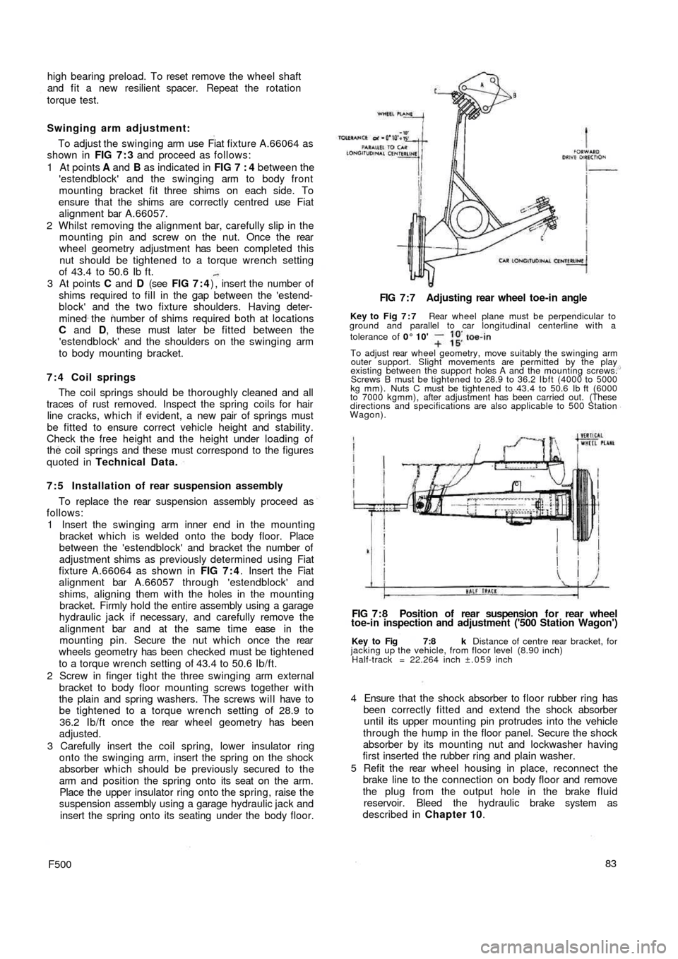
FIG 7 : 8 Position of rear suspension f o r rear wheel
toe-in inspection and adjustment ('500 Station Wagon') FIG 7 : 7 Adjusting rear wheel toe-in angle
Key to Fig 7 : 7 Rear wheel plane must be perpendicular to
ground and parallel to car longitudinal centerline with a
tolerance of 0° 10'
To adjust rear wheel geometry, move suitably the swinging arm
outer support. Slight movements are permitted by the play
existing between the support holes A and the mounting screws.
Screws B must be tightened to 28.9 to 36.2 Ibft (4000 to 5000
kg mm). Nuts C must be tightened to 43.4 to 50.6 Ib ft (6000
to 7000 kgmm), after adjustment has been carried out. (These
directions and specifications are also applicable to 500 Station
Wagon).
Page 77 of 128
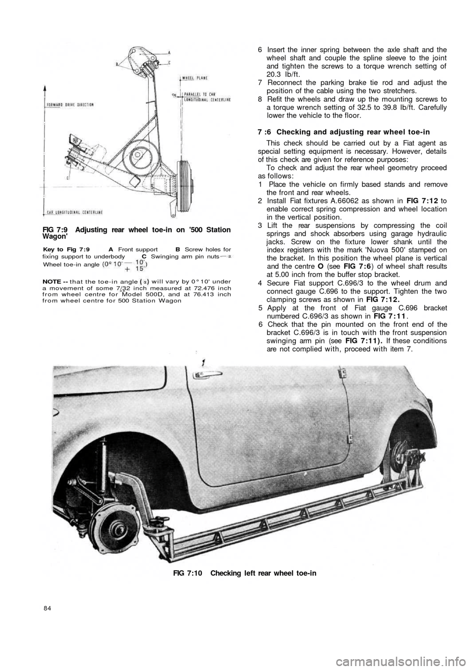
FIG 7:9 Adjusting rear wheel toe-in on '500 StationWagon'
FIG 7:10 Checking left rear wheel toe-in
84
6 Insert the inner spring between the axle shaft and the
wheel shaft and couple the spline sleeve to the joint
and tighten the screws to a torque wrench setting of
20.3 Ib/ft.
7 Reconnect the parking brake tie rod and adjust the
position of the cable using the two stretchers.
8 Refit the wheels and draw up the mounting screws to
a torque wrench setting of 32.5 to 39.8 Ib/ft. Carefully
lower the vehicle to the floor.
7 :6 Checking and adjusting rear wheel toe-in
This check should be carried out by a Fiat agent as
special setting equipment is necessary. However, details
of this check are given for reference purposes:
To check and adjust the rear wheel geometry proceed
as follows:
1 Place the vehicle on firmly based stands and remove
the front and rear wheels.
2 Install Fiat fixtures A.66062 as shown in FIG 7:12 to
enable correct spring compression and wheel location
in the vertical position.
3 Lift the rear suspensions by compressing the coil
springs and shock absorbers using garage hydraulic
jacks. Screw on the fixture lower shank until the
index registers with the mark 'Nuova 500' stamped on
the bracket. In this position the wheel plane is vertical
and the centre O (see FIG 7 : 6) of wheel shaft results
at 5.00 inch from the buffer stop bracket.
4 Secure Fiat support C.696/3 to the wheel drum and
connect gauge C.696 to the support. Tighten the two
clamping screws as shown in FIG 7:12.
5 Apply at the front of Fiat gauge C.696 bracket
numbered C.696/3 as shown in FIG 7:11.
6 Check that the pin mounted on the front end of the
bracket C.696/3 is in touch with the front suspension
swinging arm pin (see FIG 7:11). If these conditions
are not complied with, proceed with item 7.
Wheel toe-in angle
will vary by 0° 10' under
a movement of some 7/32 inch measured at 72.476 inch
from wheel centre for Model 500D, and at 76.413 inch
from wheel centre for 500 Station Wagon NOTE - - that the toe-in angle
Key to Fig 7 : 9 A Front support B Screw holes for
fixing support to underbody C Swinging arm pin nuts
Page 80 of 128
CHAPTER 8
FRONT SUSPENSION AND HUBS
8:1
8:2
8:3
8:4
8:5
8:6Description
Front suspension removal and dismantling
Leaf spring
Swinging arms
Kingpin housing
Steering knuckle and wheel hub
8:1 Description
The independent front suspension assembly fitted to
the 'new 500' range comprises a transverse leaf spring
which is anchored to the body through two rubber
mountings and kingpins through 'estendblocks' as
shown in FIG 8:1. The leaf spring also acts as an anti-
roll bar which gives normal spring reaction even when the
front road wheels encounter a rough road surface.
Special polyethylene insulating strips are fitted
between the five springs leaves which are all clamped
together by t w o rubber cushioned clamps.
Upper movement of the kingpins in the swinging arm
is obtained by 'estendblocks'. The half arms are anchored
to the body as shown in FIG 8 : 3 and pivot on their pins
through rubber bushes. Double acting hydraulic shock
absorbers are fitted to the kingpin housings at the lower
end and anchored at the top to the vehicle body. Two
rubber buffers are secured to brackets mounted onto the
body to limit the spring oscillations. The spring centre
bolt is also fitted with a rubber pad.
8 : 2 Front suspension removal and
dismantling
To remove the front suspension assembly proceed as
follows:
F50087
1 Remove the hub caps and carefully slacken the road
wheel retaining bolts. Using a garage hydraulic jack
raise the front of the vehicle and place on firmly
based stands. Remove the road wheels.
2 Disconnect the steering linkages from the pitman arm,
the drag link and the steering knuckle arms.
3 Remove the shock absorber upper mounting nut from
the body, lift away the half rubber bush and push d o w n
the outer cylinder.
4 Blank off the brake fluid reservoir outlet by inserting
a suitable wooden peg through the reservoir filler
opening and disconnect the brake hydraulic lines at
the wheel cylinders.
5 Fit Fiat crossbeam Arr.2072 under the leaf spring
and support this, using a garage hydraulic jack.
6 Remove the self-locking nut securing the leaf spring
to the kingpin housing and ease o u t the spring
mounting bolt taking care not to damage the thread.
Also remove the nuts securing the swinging arm pin
to studs on the body and remove the swinging arm
assembly. Carefully lift out the adjusting shims and
spacers from the studs making a careful note of the
number of the shims and their locations.
7 Remove the nuts securing the leaf spring elastic
mounting to the body (see FIG 8 : 4) , and lower the 8:7
8:8
8:9
8:10
8:11Hydraulic damper
Front suspension assembly and
installation
Steering geometry
Modifications
Fault diagnosis