oil pressure FIAT 500 1961 1.G Owner's Manual
[x] Cancel search | Manufacturer: FIAT, Model Year: 1961, Model line: 500, Model: FIAT 500 1961 1.GPages: 128, PDF Size: 9.01 MB
Page 97 of 128
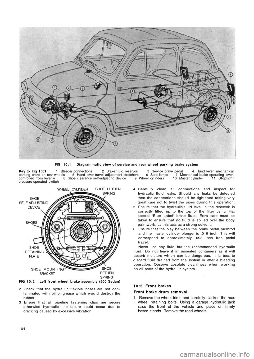
FIG 10:1 Diagrammatic view of service and rear wheel parking brake system
Key to Fig 10:1 1 Bleeder connections 2 Brake fluid reservoir 3 Service brake pedal 4 Hand lever, mechanical
parking brake on rear wheels 5 Hand lever travel adjustment stretchers 6 Stop lamps 7 Mechanical brake operating lever,
controlled from lever 4 8 Shoe clearance self-adjusting device 9 Wheel cylinders 10 Master cylinder 11 Stoplight
pressure-operated switch
FIG 10:2 Left front wheel brake assembly (500 Sedan)
SHOE
RETURN
SPRINGSHOE MOUNTING
BRACKET SHOE
RETAINING
PLATE SHOES
DEVICESHOE
SELF-ADJUSTING
WHEEL CYLINDERSHOE RETURNSPRING
2 Check that the hydraulic flexible hoses are not con-
taminated with oil or grease which would destroy the
rubber.
3 Ensure that all pipeline fastening clips are secure
otherwise hydraulic line failure could occur due to
cracking caused by excessive vibration.
104
4 Carefully clean all connections and inspect for
hydraulic fluid leaks. Should any leaks be detected
then the connections should be tightened taking very
great care not to twist the pipes during this operation.
5 Ensure that the hydraulic fluid level in the reservoir is
correctly filled up to the top of the filter using Fiat
special 'Blue Label' brake fluid. Extra care must be
taken to ensure that no fluid is spilled over the body
paintwork, as this acts as a strong solvent.
6 Ensure that the play between the brake pedal pushrod
and the master cylinder plunger is .019 inch. This will
correspond to approximately .098 inch free pedal
travel.
Never use any fluid but the recommended hydraulic
fluid. Do not leave it in unsealed containers as it will
absorb moisture which can be dangerous. It is best to
discard fluid drained from the system or after a bleeding
operation. Observe absolute cleanliness when working
on all parts of the hydraulic system.
10:3 Front brakes
Front brake drum removal:
1 Remove the wheel trims and carefully slacken the road
wheel retaining bolts. Using a garage hydraulic jack
raise the front of the vehicle and place on firmly
based stands. Remove the road wheels.
Page 98 of 128
2 Using Fiat puller A.46023 as shown in FIG 8 : 9
remove the wheel grease cap.
3 Using a universal t w o leg puller or Fiat puller A.40005
together w i t h items 1 and 9 remove the wheel hub/
drum assembly having first extracted the splitpin if
fitted and released the hub retaining nut (see FIG
8:10).
Dismantling brake unit:
1 Using a compressed air jet thoroughly clean all com-
ponents of the brake assembly.
2 Make a note of the location of the shoe return springs
and gently ease the shoes away from the brake
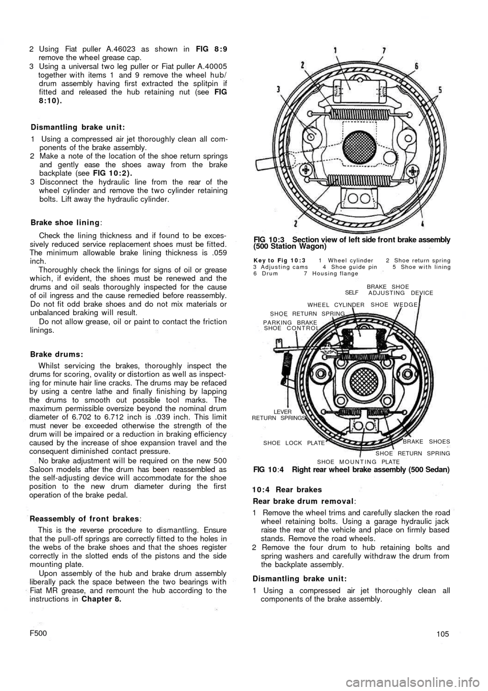
backplate (see FIG 10:2).
3 Disconnect the hydraulic line from the rear of t h e
wheel cylinder and remove the t w o cylinder retaining
bolts. Lift away the hydraulic cylinder.
Brake shoe lining:
Check the lining thickness and if found to be exces-
sively reduced service replacement shoes must be fitted.
The minimum allowable brake lining thickness is .059
inch.
Thoroughly check the linings for signs of oil or grease
which, if evident, the shoes must be renewed and the
drums and oil seals thoroughly inspected for the cause
of oil ingress and the cause remedied before reassembly.
Do not fit odd brake shoes and do not mix materials or
unbalanced braking will result.
Do not allow grease, oil or paint to contact the friction
linings.
Brake drums:
Whilst servicing the brakes, thoroughly inspect the
drums for scoring, ovality or distortion as well as inspect-
ing for minute hair line cracks. The drums may be refaced
by using a centre lathe and finally finishing by lapping
the drums to smooth out possible tool marks. The
maximum permissible oversize beyond the nominal drum
diameter of 6.702 to 6.712 inch is .039 inch. This limit
must never be exceeded otherwise the strength of the
drum will be impaired or a reduction in braking efficiency
caused by the increase of shoe expansion travel and the
consequent diminished contact pressure.
No brake adjustment will be required on the new 500
Saloon models after the drum has been reassembled as
the self-adjusting device will accommodate for the shoe
position to the new drum diameter during the first
operation of the brake pedal.
Reassembly of front brakes:
This is the reverse procedure to dismantling. Ensure
that the pull-off springs are correctly fitted to the holes in
the webs of the brake shoes and that the shoes register
correctly in the slotted ends of the pistons and the
side
mounting plate.
Upon assembly of the hub and brake drum assembly
liberally pack the space between the two bearings w i t h
Fiat MR grease, and remount the hub according to the
instructions in Chapter 8.
F500
FIG 10:3 Section view of left side f r o n t brake assembly
(500 Station Wagon)
Key to Fig 10:3 1 Wheel cylinder 2 Shoe return spring
3 Adjusting cams 4 Shoe guide pin 5 Shoe with lining
6 Drum 7 Housing flange
BRAKE SHOE
ADJUSTING DEVICE
SHOE WEDGE
SELF
WHEEL CYLINDER
SHOE RETURN SPRING
PARKING BRAKE
SHOE CONTROL
RETURN SPRINGS
LEVER
SHOE LOCK PLATEBRAKE SHOES
SHOE RETURN SPRING
SHOE MOUNTING PLATE
FIG 1 0:4 Right rear wheel brake assembly (500 Sedan)
10:4 Rear brakes
Rear brake drum removal:
1 Remove the wheel trims and carefully slacken the road
wheel retaining bolts. Using a garage hydraulic jack
raise the rear of t h e vehicle and place on firmly based
stands. Remove the road wheels.
2 Remove the four drum to hub retaining bolts and
spring washers and carefully withdraw the drum from
the backplate assembly.
Dismantling brake unit:
1 Using a compressed air jet thoroughly clean all
components of the brake assembly.
105
Page 102 of 128
10:9 Brake fluid reservoir
The reservoir is located in the front compartment to the
side of the fuel tank as shown in FIG 10:9. Should it be
necessary to detach the fluid outlet line from the reservoir
the outlet hole must be blanked off using a tapered
wooden peg of suitable length so that the cap may be
replaced to prevent the ingress of foreign matter into
the reservoir and the absorbtion of moisture, oil or petrol
vapours which would alter the properties of the hydraulic
fluid.
A special filter is fitted into the top of the reservoir
through which all fluid used for topping-up the reservoir
must pass to ensure utmost inner cleanliness of the
hydraulic system.
10:10 Bleeding the system
This is not a routine maintenance operation and is only
necessary if air has entered the hydraulic system because
parts have been dismantled or because the f l u i d level in
the reservoir has dropped so low that air has been drawn
into the main feed pipe to the master cylinders.
1 Fill the reservoir w i t h Fiat 'Blue Label' hydraulic fluid.
During the bleeding operation fluid will be used and
constant topping-up of the supply reservoir will be
needed. If this is not done it is possible for air to enter
the master cylinder main feed pipe which will nullify
the operation and necessitate a fresh start.
2 Attach a length of rubber or plastic tubing to the
bleeder screw on the rear wheel cylinder furthermost
from the master cylinder. Immerse the free end of the
tube in a small volume of hydraulic brake fluid in a
clean jar.
3 Open the bleed screw one turn and get a second
operator to press down slowly on the brake pedal. After
a full stroke let the pedal return without assistance,
pause a moment and repeat the d o w n stroke. At first
there will be air bubbles issuing from the bleed tube,
but when fluid alone is ejected, hold the pedal firmly
down on the floor panel and tighten the bleed screw.
Repeat this operation on the other rear brake and then
repeat the operation on the two front brakes.
4 On completion, top-up the fluid in the reservoir to the
correct level. Discard all dirty fluid. If fluid is perfectly
clean, let it stand for twenty four hours to become
clear of air bubbles before using it again.
10:11 Hand parking brake
Normally with the new 500 Sedan model automatic
brake adjusting device, adjustment of the rear brakes
will take up excessive handbrake travel.
If there is excessive travel on the handbrake of the
Sedan model at any time, or in the case of Station Wagon
model even after the rear brakes have been manually
adjusted, suspect worn brake shoe linings or stretched
handbrake cables. Examine the linings and fit replace-
ment shoes if necessary. Check the action of the hand
parking brake again and if there is still too much travel
before the brakes are applied it is permissible to take up as
follows:
1 It is essential to ensure that the rear shoes are correctly
adjusted as described in Section 10:2.
2 Apply the hand parking brake lever until the pawl
engages with the ratchet at the second notch.
F500
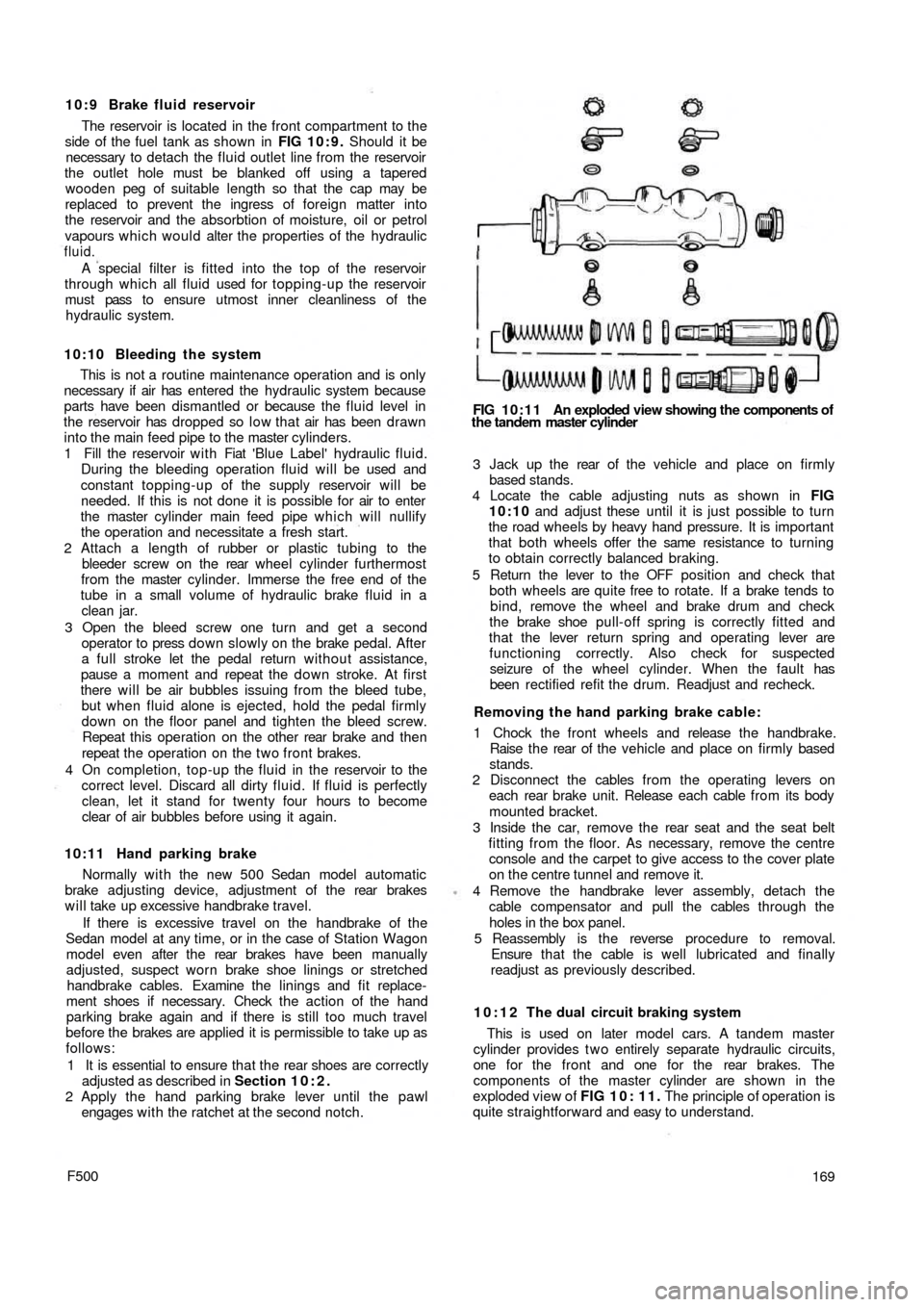
FIG 10:11 An exploded view showing the components of
the tandem master cylinder
3 Jack up the rear of t h e vehicle and place on firmly
based stands.
4 Locate the cable adjusting nuts as shown in FIG
10:10 and adjust these until it is just possible to turn
the road wheels by heavy hand pressure. It is important
that both wheels offer the same resistance to turning
to obtain correctly balanced braking.
5 Return the lever to the OFF position and check that
both wheels are quite free to rotate. If a brake tends to
bind, remove the wheel and brake drum and check
the brake shoe pull-off spring is correctly fitted and
that the lever return spring and operating lever are
functioning correctly. Also check for suspected
seizure of the wheel cylinder. When the fault has
been rectified refit the drum. Readjust and recheck.
Removing the hand parking brake cable:
1 Chock the front wheels and release the handbrake.
Raise t h e rear of the vehicle and place on firmly based
stands.
2 Disconnect the cables from the operating levers on
each rear brake unit. Release each cable from its body
mounted bracket.
3 Inside the car, remove the rear seat and the seat belt
fitting from the floor. As necessary, remove the centre
console and the carpet to give access to the cover plate
on the centre tunnel and remove it.
4 Remove the handbrake lever assembly, detach the
cable compensator and pull the cables through the
holes in the box panel.
5 Reassembly is the reverse procedure to removal.
Ensure t h a t the cable is well lubricated and finally
readjust as previously described.
10:12 The dual circuit braking system
This is used on later model cars. A tandem master
cylinder provides t w o entirely separate hydraulic circuits,
one for the front and one for the rear brakes. The
components of the master cylinder are shown in the
exploded view of FIG 1 0 : 1 1 . The principle of operation is
quite straightforward and easy to understand.
169
Page 103 of 128
When the pedal is applied, it moves the rear (primary)
piston to pressurise the front brakes through the rear port.
This, in turn, forces the front (secondary) piston down the
bore to pressurise the rear brake circuit through the front
port. In the event of a failure in the primary circuit, the
primary piston moves into direct contact with the second-
ary piston and full braking is still available on the rear
wheels. If a leak occurs in the rear circuit, the secondary
piston is moved to the end of the bore, sealing off the out-
let port and full braking pressure is applied to the t w o front
brakes.
With two fluid reservoirs connected to the inlets 3 and 5
the two circuits are fully independent.
The remaining components in the braking system are
similar to those used in the earlier single circuit layout.
10:13 Fault diagnosis
(a) 'Spongy' pedal
1 Leak in t h e system
2 Worn master cylinder
3 Leaking wheel cylinders
4 Air in the system
5 Gaps between shoes and underside of linings
110
(b) Excessive pedal movement
1 Check 1 and 4 in (a)
2 Excessive lining wear
3 Very low fluid level in supply reservoir
4 Too much free movement of pedal
(c) Brakes grab or pull to one side
1 Brake backplate loose
2 Scored, cracked or distorted drum
3 High spots on drum
4 Unbalanced shoe adjustment
5 Wet or oily linings
6 Worn or loose spring fixings
7 Front suspension or rear suspension anchorages
loose
8 Worn steering connections
9 Mixed linings of different grades
10 Uneven tyre pressure
11 Broken shoe return springs
12 Seized handbrake cable
Page 105 of 128
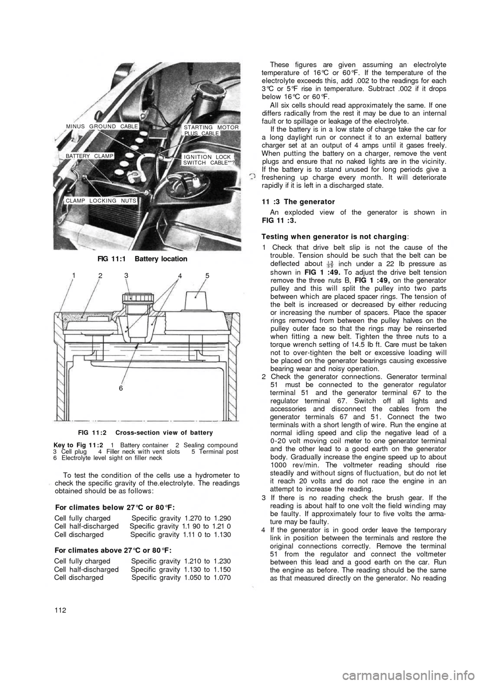
FIG 11:1 Battery location
CLAMP LOCKING NUTSIGNITION LOCK !
SWITCH CABLE*"? BATTERY CLAMP MINUS GROUND CABLE
STARTING MOTOR
PLUS CABLE
65
4 3
2 1
FIG 11:2 Cross-section view of battery
Key to Fig 11:2 1 Battery container 2 Sealing compound
3 Cell plug 4 Filler neck with vent slots 5 Terminal post
6 Electrolyte level sight on filler neck
To test the condition of the cells use a hydrometer to
check the specific gravity of the.electrolyte. The readings
obtained should be as follows:
For climates below 27°C or 80°F:
Cell fully charged Specific gravity 1.270 to 1.290
Cell half-discharged Specific gravity 1.1 90 to 1.21 0
Cell discharged Specific gravity 1.11 0 to 1.130
For climates above 27°C or 80°F:
Cell fully charged Specific gravity 1.210 to 1.230
Cell half-discharged Specific gravity 1.130 to 1.150
Cell discharged Specific gravity 1.050 to 1.070
112These figures are given assuming an electrolyte
temperature of 16°C or 60°F. If the temperature of the
electrolyte exceeds this, add .002 to the readings for each
3°C or 5°F rise in temperature. Subtract .002 if it drops
below 16°C or 60°F.
All six cells should read approximately the same. If one
differs radically from the rest it may be due to an internal
fault or to spillage or leakage of the electrolyte.
If the battery is in a low state of charge take the car for
a long daylight run or connect it to an external battery
charger set at an output of 4 amps until it gases freely.
When putting the battery on a charger, remove the vent
plugs and ensure that no naked lights are in the vicinity.
If the battery is to stand unused for long periods give a
freshening up charge every month. It will deteriorate
rapidly if it is left in a discharged state.
11 :3 The generator
An exploded view of the generator is shown in
FIG 11 : 3 .
Testing when generator is not charging:
1 Check that drive belt slip is not the cause of the
trouble. Tension should be such that the belt can be
deflected about
inch under a 22 Ib pressure as
shown in FIG 1 :49. To adjust the drive belt tension
remove the three nuts B, FIG 1 :49, on the generator
pulley and this will split the pulley into two parts
between which are placed spacer rings. The tension of
the belt is increased or decreased by either reducing
or increasing the number of spacers. Place the spacer
rings removed from between the pulley halves on the
pulley outer face so that the rings may be reinserted
when fitting a new belt. Tighten the three nuts to a
torque wrench setting of 14.5 Ib ft. Care must be taken
not to over-tighten the belt or excessive loading will
be placed on the generator bearings causing excessive
bearing wear and noisy operation.
2 Check the generator connections. Generator terminal
51 must be connected to the generator regulator
terminal 51 and the generator terminal 67 to the
regulator terminal 67. Switch off all lights and
accessories and disconnect the cables from the
generator terminals 67 and 5 1 . Connect the two
terminals with a short length of wire. Run the engine at
normal idling speed and clip the negative lead of a
0-20 volt moving coil meter to one generator terminal
and the other lead to a good earth on the generator
body. Gradually increase the
engine speed up to about
1000 rev/min. The voltmeter reading should rise
steadily and without signs of fluctuation, but do not let
it reach 20 volts and do not race the engine in an
attempt to increase the reading.
3 If there is no reading check the brush gear. If the
reading is about half to one volt the field winding may
be faulty. If approximately four to five volts the arma-
ture may be faulty.
4 If the generator is in good order leave the temporary
link in position between the terminals and restore the
original connections correctly. Remove the terminal
51 from the regulator and connect the voltmeter
between this lead and a good earth on the car. Run
the engine as before. The reading should be the same
as that measured directly on the generator. No reading
Page 116 of 128
Lamp brilliance varies w i t h the speed of t h e car:
Check the condition of the battery. Examine the battery
connections. Make sure they are tight and renew faulty
cables.
11:10 Panel and warning lights:
All the gauges are clustered in a single instrument
mounted on the dashboard above the steering column.
Incorporated in this cluster is the parking light pilot light,
generator charge indicator, fuel reserve supply indicator,
low oil pressure indicator, and the speedometer w i t h
mileage recorder.
The parking lamp indicator glows green when the
ignition lock switch key is in either position 1 or 2 once
the toggle switch on the instrument panel has been
operated.
The generator charge indicator shows red only when
the ignition is turned on. It should be extinguished when
the generator output is sufficient for battery charge
(12.6 ± 0.2 volts) with the engine running at a speed
of 1100 rev/min and the headlights switched off.
The fuel reserve supply indicator shows red only when
the ignition is turned on and the amount of fuel in the
petrol tank has dropped to approximately .8 to 1.1
Imp. gallons.
The low oil pressure indicator shows red only when the
ignition is turned on and should be extinguished when
the oil pressure reaches 7.1 to 21.3 Ib/sq in, and opens
the sending unit contacts. Once the engine is at normal
operating temperature but at a speed below 1000 rev/
min the indicator might light up even the pressure is under
control and with normal operation.
All the bulbs fitted to the above described units are of
the tubular 2.5W type and to renew a bulb extract the
bulb holder from the rear of t h e instrument cluster and
release the bulb which is attached by a normal bayonet
coupling.
Fuel reserve supply indicator sender u n i t:
The fuel reserve supply indicator should be checked for
correct indication by allowing the fuel tank to empty and
then inserting .8 to 1.1 Imp. gallons at which stage the
light should extinguish. Any failure to do so should be
checked as follows:
1 Ensure that the indicator bulb operates correctly.
2 Check for complete circuit between the sender unit and
the indicator bulb.
3 If the sender unit float bracket is distorted the bulb
will
indicate a reserve supply of fuel greater or smaller than
specified. The bracket should be adjusted to give
correct indication of fuel level.
4 The sender unit could have been inadvertantly
damaged in which case the unit must be renewed.
11 :11 The horn
The horn circuit comprises the horn, push button at the
centre of the steering wheel and normal earth return
electrical circuit through the car body. One terminal is
connected to the battery whilst the other to the push
button on the steering wheel which when the button is
depressed the circuit will be closed so causing the horn
to operate.
F500
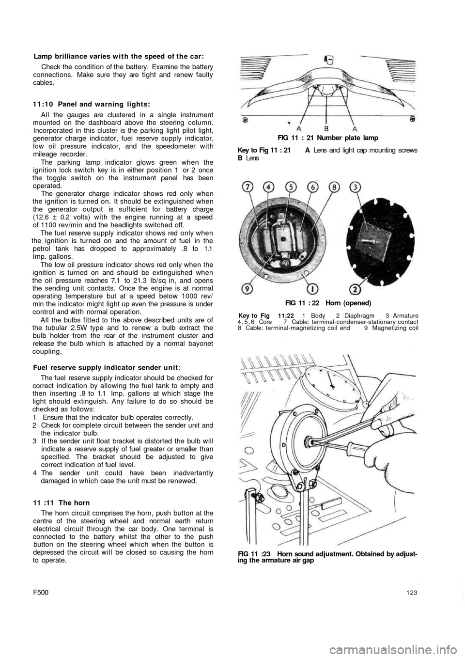
FIG 11 : 21 Number plate lamp
Key to Fig 11 : 21 A Lens and light cap mounting screws
B Lens
FIG 11 : 22 Horn (opened)
Key to Fig 11:22 1 Body 2 Diaphragm 3 Armature
4,5,6 Core 7 Cable: terminal-condenser-stationary contact
8 Cable: terminal-magnetizing coil end 9 Magnetizing coil
FIG 11 :23 Horn sound adjustment. Obtained by adjust-
ing the armature air gap
123
Page 121 of 128
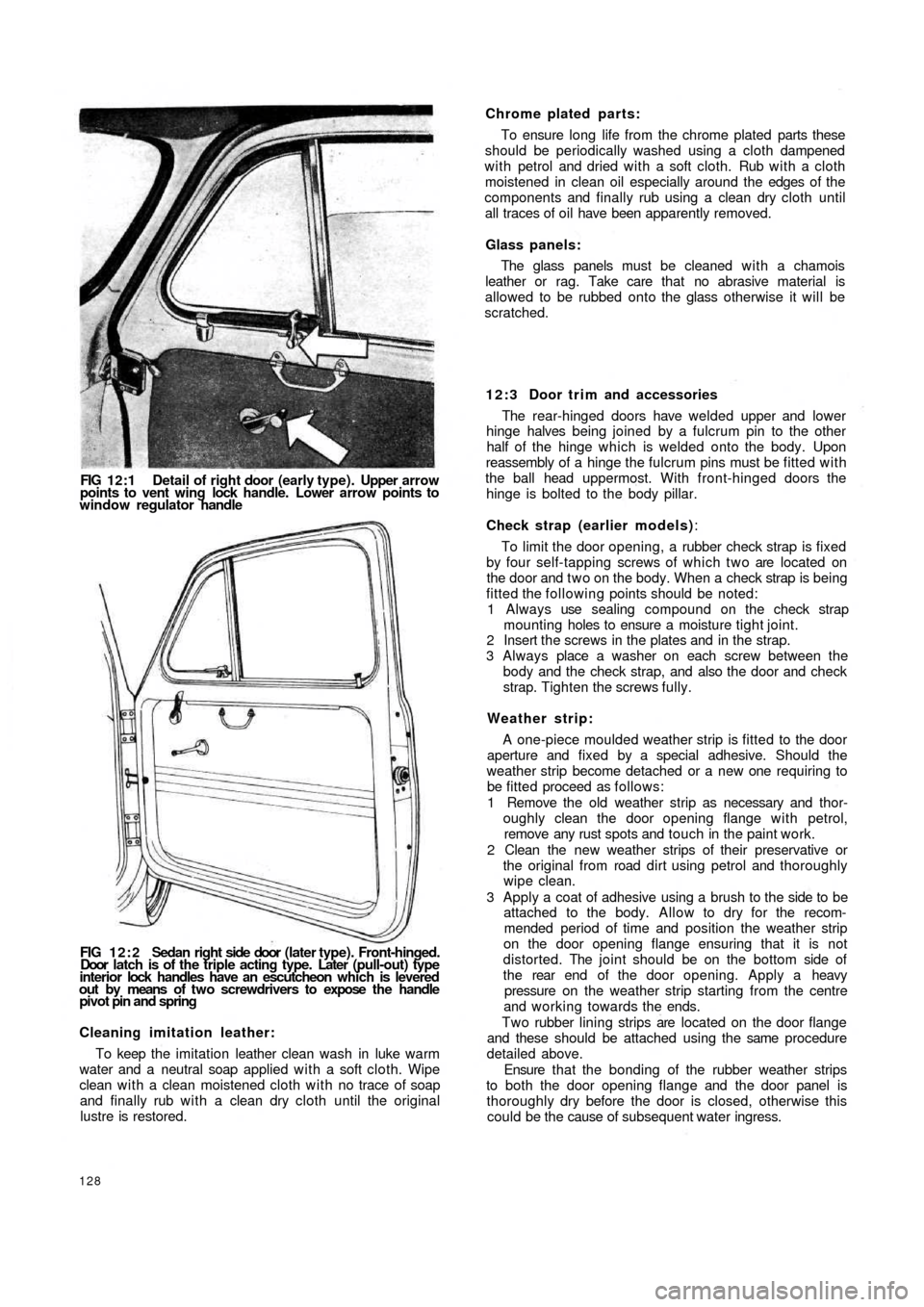
FIG 12:1 Detail of right door (early type). Upper arrow
points to vent wing lock handle. Lower arrow points to
window regulator handle
FIG 1 2 : 2 Sedan right side door (later type). Front-hinged.
Door latch is of the triple acting type. Later (pull-out) type
interior lock handles have an escutcheon which is levered
out by means of t w o screwdrivers to expose the handle
pivot pin and spring
Cleaning imitation leather:
To keep the imitation leather clean wash in luke warm
water and a neutral soap applied with a soft cloth. Wipe
clean with a clean moistened cloth with no trace of soap
and finally rub with a clean dry cloth until the original
lustre is restored.
128
Chrome plated parts:
To ensure long life from the chrome plated parts these
should be periodically washed using a cloth dampened
with petrol and dried with a soft cloth. Rub with a cloth
moistened in clean oil especially around the edges of the
components and finally rub using a clean dry cloth until
all traces of oil have been apparently removed.
Glass panels:
The glass panels must be cleaned w i t h a chamois
leather or rag. Take care that no abrasive material is
allowed to be rubbed onto the glass otherwise it will be
scratched.
12:3 Door trim and accessories
The rear-hinged doors have welded upper and lower
hinge halves being joined by a fulcrum pin to the other
half of the hinge which is welded onto the body. Upon
reassembly of a hinge the fulcrum pins must be fitted with
the ball head uppermost. With front-hinged doors the
hinge is bolted to the body pillar.
Check strap (earlier models):
To limit the door opening, a rubber check strap is fixed
by four self-tapping screws of which two are located on
the door and t w o on the body. When a check strap is being
fitted the following points should be noted:
1 Always use sealing compound on the check strap
mounting holes to ensure a moisture t i g h t j o i n t .
2 Insert the screws in the plates and in the strap.
3 Always place a washer on each screw between the
body and the check strap, and also the door and check
strap. Tighten the screws fully.
Weather strip:
A one-piece moulded weather strip is fitted to the door
aperture and fixed by a special adhesive. Should the
weather strip become detached or a new one requiring to
be fitted proceed as follows:
1 Remove the old weather strip as necessary and thor-
oughly clean the door opening flange with petrol,
remove any rust spots and touch in the paint work.
2 Clean the new weather strips of their preservative or
the original from road dirt using petrol and thoroughly
wipe
clean.
3 Apply a coat of adhesive using a brush to the side to be
attached to the body. Allow to dry for the recom-
mended period of time and position the weather strip
on the door opening flange ensuring that it is not
distorted. The joint should be on the bottom side of
the rear end of the door opening. Apply a heavy
pressure on the weather strip starting from the centre
and working towards the ends.
Two rubber lining strips are located on the door flange
and these should be attached using the same procedure
detailed above.
Ensure that the bonding of the rubber weather strips
to both the door opening flange and the door panel is
thoroughly dry before the door is closed, otherwise this
could be the cause of subsequent water ingress.