seat adjustment FIAT 500 1962 1.G Owner's Manual
[x] Cancel search | Manufacturer: FIAT, Model Year: 1962, Model line: 500, Model: FIAT 500 1962 1.GPages: 128, PDF Size: 9.01 MB
Page 79 of 128
A tolerance of —10'.+ 15' is permitted providing
that the value is the same for both rear wheels. It is
important that both rear wheels are set to the same
angle otherwise uneven tyre wear and adverse handl-
ing conditions will result. When the wheel is parallel to
the centre line of the vehicle the pin of bracket
C.696/3 will be .216 inch apart from the pin of the
front suspension swinging arm.
7 Release the swinging arm outer support to body
mounting screws and position arm in such a way as to
obtain the condition as described in Number 6 above.
After the adjustment has been completed tighten
the outer support mounting screws to a torque wrench
setting of 28.9 to 36.2 Ib/ft. Also tighten the two
swinging arm pin nuts C (see FIG 7 : 7) to a torque
wrench setting of 43.4 to 50.6 Ib/ft. Take off the gauge
C.696 w i t h bracket and support C.696/3, and repeat
the check and adjustment operations on the other
wheel. Care must be taken to ensure that bracket
C.696/3 is reversed from the position previously used.
New 500 type 500D, 110F and 110L sedan and
station wagon:
After the rear suspension has been replaced, check
and, if necessary adjust the rear wheel geometry.
1 Inflate the tyres to the normal operating pressures.
2 Lower the car body so that the rear wheels are set at
90 deg. to the floor. This condition is obtained when
the lowermost portion of the sump is 6.61 inches from
the floor level for the new 500D model or the centre
rear bracket for jacking up the rear of t h e vehicle
8.9 inches from the floor level for the 500 Station
Wagon.
3 With the vehicle set to the above conditions check the
wheel geometry. The wheel plane must converge w i t h
the centre line of the vehicle by an angle of 0 deg. 10'
(—10', +15') toeing in at the front.
4 The wheel plane must be 22.343 ± .059 inches from
the centre line of the vehicle for the 500D model.
Whereas for the 500 Station Wagon the distance must
be 22.264 ± .059 inches.
5 To adjust the rear wheel toe-in adjust the positions of
the mounting screws A and B as shown in FIG 7:7.
86
7:7 Modifications
The new 500 Sedan (110F) and late 500 Station
Wagon are fitted with modified wheels side flexible
joints and rear control arm as shown in FIG 7:13.
Together w i t h these modifications a new design rear
coil spring has been fitted details of which are given in
Technical Data.
7 : 8 Fault diagnosis
(a) Irregular or abnormal tyre wear
1 Incorrect tyre pressure
2 Wheels out of balance
3 Wheels off centre
4 Misadjusted brakes
5 Weak or broken coil springs
6 Excessive load
7 Incorrect wheel alignment
(b) Sag on one wheel
1 Incorrect tyre pressure
2 Weak or broken coil spring
3 Wear of shock absorber causing poor dampening
action
(c) Squeaks, thumps or rattles
1 Wheels out of balance
2 Wheels off centre
3 Misadjusted brakes
4 Weak or broken coil springs or spring seats dislodged
5 Wear of shock absorbers causing poor dampening
action
6 Worn rubber bushings in control arms
7 Poor lubrication of wheel bearings
(d) Pull to one side
1 Incorrect tyre pressure
2 Misadjusted brakes
3 Distorted suspension arm
Page 85 of 128
1
2
6
3
8
11
13
17
19
22
25
27
29
31
33
36
35 323430 28
26
24232120 ,1816 15 14 12 10 .9 .15 4
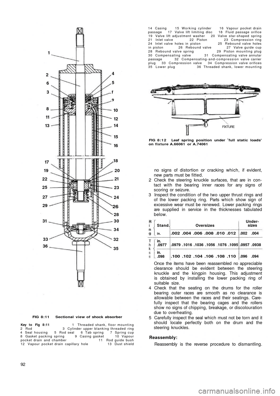
FIG 8:11 Sectional view of shock absorber
Key to Fig 8:11 1 Threaded shank, floor mounting
2 R o d 3 Cylinder upper blanking threaded ring
4 Seal housing 5 Rod seal 6 Tab spring 7 Spring cup
8 Gasket packing spring 9 Casing gasket 10 Vapour
pocket drain and chamber 11 Rod guide bush
12 Vapour pocket drain capillary hole 13 Dust shield
92
14 Casing 15 Working cylinder 16 Vapour pocket drain
passage 17 Valve lift limiting disc 18 Fluid passage orifice
19 Valve lift adjustment washer 20 Valve star-shaped spring
21 Inlet valve 22 Piston 23 Compression ring
24 Inlet valve holes in piston 25 Rebound valve holes
in piston 26 Rebound valve 27 Valve guide cup
28 Rebound valve spring 29 Piston mounting plug
30 Compensating valve 31 Compensating valve annular
passage 32 Compensating-and-compression valve carrier
plug 33 Compression valve 34 Compression valve orifices
35 Lower plug 36 Threaded shank, lower mounting
FIXTURE
FIG 8:12 Leaf spring position under full static loads'
on fixture A.66061 or A.74061
no signs of distortion or cracking which, if evident,
new parts must be fitted.
2 Check the steering knuckle surfaces, that are in con-
tact with the bearing inner races for any signs of
scoring or seizure.
3 Inspect the condition of the two upper thrust rings and
of the lower packing ring. Parts which show sign of
excessive wear must be renewed. Lower packing rings
are supplied in service in the thicknesses tabulated
below.
Once the items have been reassembled no appreciable
clearance should be evident between the steering
knuckle and the kingpin housing. This adjustment
is obtained by installing the lower packing ring of
suitable size.
4 Check that the seating on the drums for the roller
bearing outer races are smooth as no clearance is
allowable between the races and their seatings. Care-
fully inspect that the bearing cages and the rollers
show no signs of chipping, breakage, or discolouration
due to overheating.
5 Carefully inspect the seal which must not be torn and it
should locate perfectly both on the drum and the
steering knuckles.
Reassembly:
Reassembly is the reverse procedure to dismantling.
OversizesUnder-
sizes
.002 .004 .006 .008 .010 .012
.0979 .1016 .1036 .1056 .1076 .1095
.100 .102 .104 .106 .108 .110
.002 .004
.0957 .0938
.096 .094
Stand.
in.
in..0977
in..098
Page 94 of 128
reassembling and during assembly liberally lubricated
using Fiat W90/M oil (SAE90 EP).
2 The pitman arm nut should be correctly positioned on
reassembly to the sector shaft and both are marked
with notches or a master tooth on the sector will mate
with a double tooth on the pitman arm which will
prevent incorrect reassembly.
3 The pitman arm nut must be tightened to a torque
wrench setting of 72 Ib/ft.
4 Fill the box up to the level and filler plug with SAE90 EP
gear oil.
Refitting the steering box:
To refit the steering box to the vehicle proceed as
follows:
1 Engage the w o r m screw f r o m the steering shaft by
gently manipulating the steering box.
2 Replace the steering box to body nuts and tighten to a
torque wrench setting of 14 to 18 Ib/ft.
3 Replace the t w o track rod pins in their seatings in the
pitman arm and tighten the self-locking nuts to a
torque wrench setting of 18 to 21 Ib/ft.
4 Replace the steering shaft to worm screw mounting
bolt, lock washer and nut.
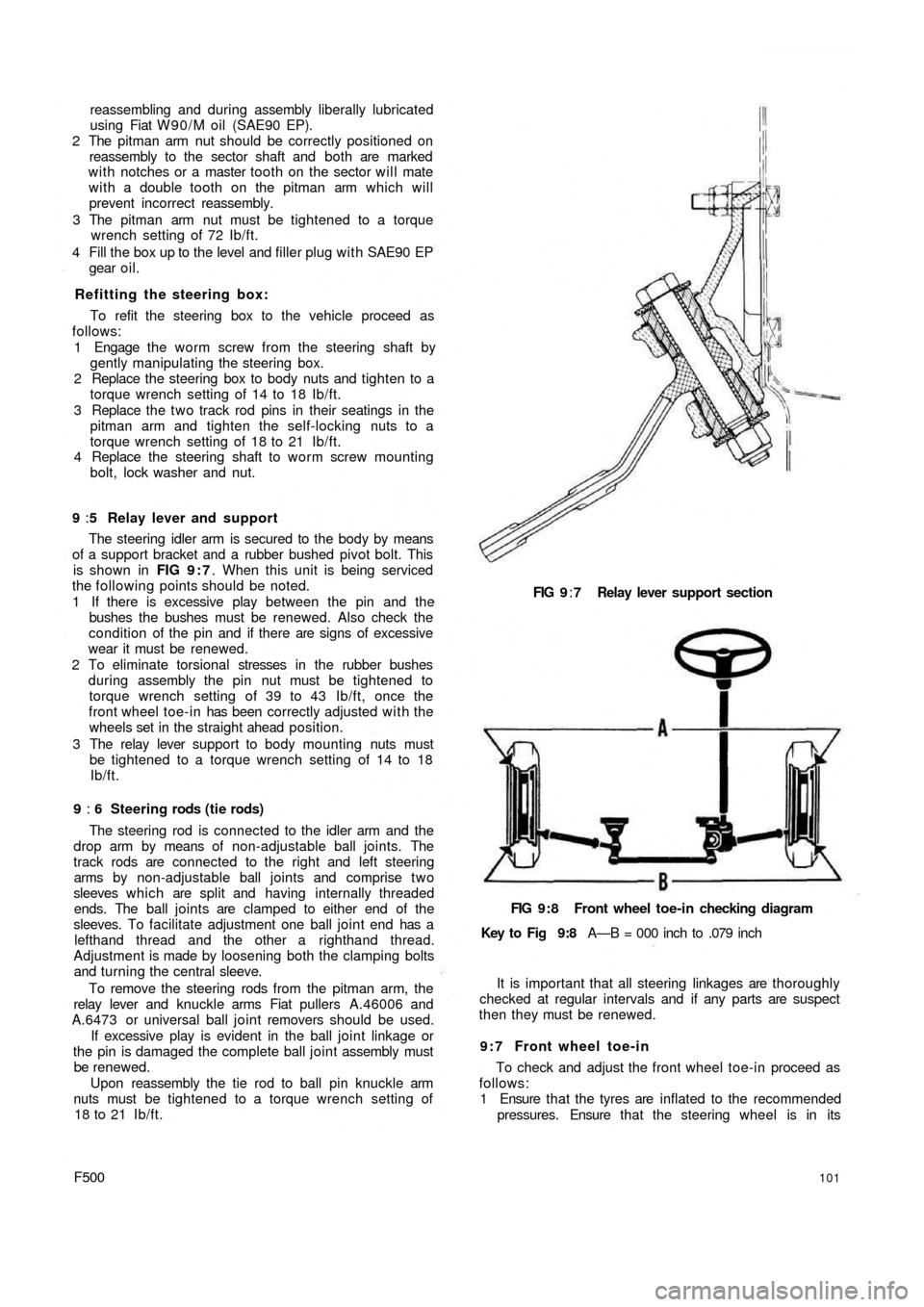
9 :5 Relay lever and support
The steering idler arm is secured to the body by means
of a support bracket and a rubber bushed pivot bolt. This
is shown in FIG 9 : 7. When this unit is being serviced
the following points should be noted.
1 If there is excessive play between the pin and the
bushes the bushes must be renewed. Also check the
condition of the pin and if there are signs of excessive
wear it must be renewed.
2 To eliminate torsional stresses in the rubber bushes
during assembly the pin nut must be tightened to
torque wrench setting of 39 to 43 Ib/ft, once the
front wheel toe-in has been correctly adjusted w i t h the
wheels set in the straight ahead position.
3 The relay lever support to body mounting nuts must
be tightened to a torque wrench setting of 14 to 18
Ib/ft.
9 : 6 Steering rods (tie rods)
The steering rod is connected to the idler arm and the
drop arm by means of non-adjustable ball joints. The
track rods are connected to the right and left steering
arms by non-adjustable ball joints and comprise t w o
sleeves which are split and having internally threaded
ends. The ball joints are clamped to either end of the
sleeves. To facilitate adjustment one ball joint end has a
lefthand thread and the other a righthand thread.
Adjustment is made by loosening both the clamping bolts
and turning the central sleeve.
To remove the steering rods from the pitman arm, the
relay lever and knuckle arms Fiat pullers A.46006 and
A.6473 or universal ball joint removers should be used.
If excessive play is evident in the ball joint linkage or
the pin is damaged the complete ball joint assembly must
be renewed.
Upon reassembly the tie rod to ball pin knuckle arm
nuts must be tightened to a torque wrench setting of
18 to 21 Ib/ft.
F500101
FIG 9:7 Relay lever support section
FIG 9:8 Front wheel toe-in checking diagram
Key to Fig 9:8 A—B = 000 inch to .079 inch
It is important that all steering linkages are thoroughly
checked at regular intervals and if any parts are suspect
then they must be renewed.
9 : 7 Front wheel toe-in
To check and adjust the front wheel toe-in proceed as
follows:
1 Ensure that the tyres are inflated to the recommended
pressures. Ensure that the steering wheel is in its
Page 102 of 128
10:9 Brake fluid reservoir
The reservoir is located in the front compartment to the
side of the fuel tank as shown in FIG 10:9. Should it be
necessary to detach the fluid outlet line from the reservoir
the outlet hole must be blanked off using a tapered
wooden peg of suitable length so that the cap may be
replaced to prevent the ingress of foreign matter into
the reservoir and the absorbtion of moisture, oil or petrol
vapours which would alter the properties of the hydraulic
fluid.
A special filter is fitted into the top of the reservoir
through which all fluid used for topping-up the reservoir
must pass to ensure utmost inner cleanliness of the
hydraulic system.
10:10 Bleeding the system
This is not a routine maintenance operation and is only
necessary if air has entered the hydraulic system because
parts have been dismantled or because the f l u i d level in
the reservoir has dropped so low that air has been drawn
into the main feed pipe to the master cylinders.
1 Fill the reservoir w i t h Fiat 'Blue Label' hydraulic fluid.
During the bleeding operation fluid will be used and
constant topping-up of the supply reservoir will be
needed. If this is not done it is possible for air to enter
the master cylinder main feed pipe which will nullify
the operation and necessitate a fresh start.
2 Attach a length of rubber or plastic tubing to the
bleeder screw on the rear wheel cylinder furthermost
from the master cylinder. Immerse the free end of the
tube in a small volume of hydraulic brake fluid in a
clean jar.
3 Open the bleed screw one turn and get a second
operator to press down slowly on the brake pedal. After
a full stroke let the pedal return without assistance,
pause a moment and repeat the d o w n stroke. At first
there will be air bubbles issuing from the bleed tube,
but when fluid alone is ejected, hold the pedal firmly
down on the floor panel and tighten the bleed screw.
Repeat this operation on the other rear brake and then
repeat the operation on the two front brakes.
4 On completion, top-up the fluid in the reservoir to the
correct level. Discard all dirty fluid. If fluid is perfectly
clean, let it stand for twenty four hours to become
clear of air bubbles before using it again.
10:11 Hand parking brake
Normally with the new 500 Sedan model automatic
brake adjusting device, adjustment of the rear brakes
will take up excessive handbrake travel.
If there is excessive travel on the handbrake of the
Sedan model at any time, or in the case of Station Wagon
model even after the rear brakes have been manually
adjusted, suspect worn brake shoe linings or stretched
handbrake cables. Examine the linings and fit replace-
ment shoes if necessary. Check the action of the hand
parking brake again and if there is still too much travel
before the brakes are applied it is permissible to take up as
follows:
1 It is essential to ensure that the rear shoes are correctly
adjusted as described in Section 10:2.
2 Apply the hand parking brake lever until the pawl
engages with the ratchet at the second notch.
F500
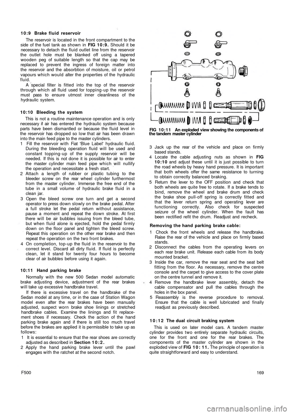
FIG 10:11 An exploded view showing the components of
the tandem master cylinder
3 Jack up the rear of t h e vehicle and place on firmly
based stands.
4 Locate the cable adjusting nuts as shown in FIG
10:10 and adjust these until it is just possible to turn
the road wheels by heavy hand pressure. It is important
that both wheels offer the same resistance to turning
to obtain correctly balanced braking.
5 Return the lever to the OFF position and check that
both wheels are quite free to rotate. If a brake tends to
bind, remove the wheel and brake drum and check
the brake shoe pull-off spring is correctly fitted and
that the lever return spring and operating lever are
functioning correctly. Also check for suspected
seizure of the wheel cylinder. When the fault has
been rectified refit the drum. Readjust and recheck.
Removing the hand parking brake cable:
1 Chock the front wheels and release the handbrake.
Raise t h e rear of the vehicle and place on firmly based
stands.
2 Disconnect the cables from the operating levers on
each rear brake unit. Release each cable from its body
mounted bracket.
3 Inside the car, remove the rear seat and the seat belt
fitting from the floor. As necessary, remove the centre
console and the carpet to give access to the cover plate
on the centre tunnel and remove it.
4 Remove the handbrake lever assembly, detach the
cable compensator and pull the cables through the
holes in the box panel.
5 Reassembly is the reverse procedure to removal.
Ensure t h a t the cable is well lubricated and finally
readjust as previously described.
10:12 The dual circuit braking system
This is used on later model cars. A tandem master
cylinder provides t w o entirely separate hydraulic circuits,
one for the front and one for the rear brakes. The
components of the master cylinder are shown in the
exploded view of FIG 1 0 : 1 1 . The principle of operation is
quite straightforward and easy to understand.
169
Page 122 of 128
Inner panels:
Imitation leather-lined masonite trim panels are fitted
to all versions of the new 500' models. The panels are
secured in the housing below the door window by means
of four stiff clips located at the top and seven spring clips
located at the bottom equally spaced around the panel
border. The fasteners are located in holes in the door
framework inner flange. The door framework has a plate
which should be bent downwards onto the trim panel
once it has been installed. This will ensure correct seating
of the trim panel in the door housing.
When the door trim panel is being reassembled ensure
that the tarred felt pad is cemented correctly on the door
inner flange so that any water that may seep in through to
the door interior from the window rubber weather strips
may be kept away from the trim panel which would
otherwise cause distortion and rapid deterioration.
12:4 Door handles and locks
The doors are provided with locks which are operated
by handles either from inside or outside the vehicle.
Removal of the lock is a straightforward operation but
upon reassembly the following procedure should be
followed:
1 Mount the handle assembly from the outside and
insert the washer onto the stud. Screw in the nut several
turns to allow correct handle-to-lock mating on final
fitting.
2 Arrange the locking handle dog so that it is horizontally
positioned and tighten the mounting nut.
3 Mount the lock to the door panel and secure w i t h three
screws and washers.
4 Fit the plate w i t h the t w o rubber guide blocks fastening
by the t w o screws.
Striker plates are fitted with shim adjustment to the
door pillars and are secured by three screws.
12:5 Removing window regulator and door glass
Window regulator:
Description:
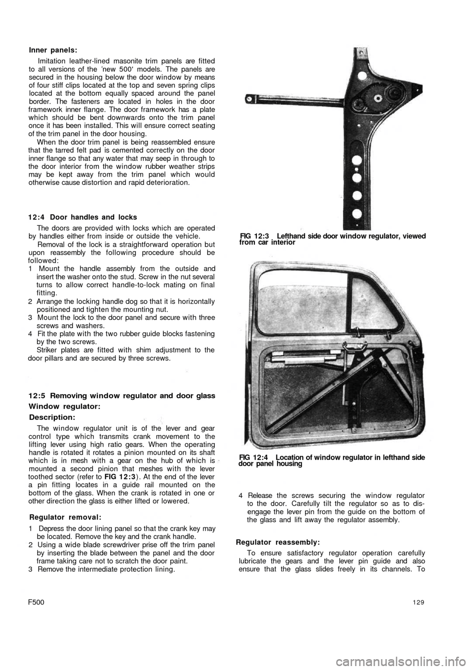
The window regulator unit is of the lever and gear
control type which transmits crank movement to the
lifting lever using high ratio gears. When the operating
handle is rotated it rotates a pinion mounted on its shaft
which is in mesh w i t h a gear on the hub of which is
mounted a second pinion that meshes with the lever
toothed sector (refer to FIG 1 2 : 3) . At the end of the lever
a pin fitting locates in a guide rail mounted on the
bottom of the glass. When the crank is rotated in one or
other direction the glass is either lifted or lowered.
Regulator removal:
1 Depress the door lining panel so that the crank key may
be located. Remove the key and the crank handle.
2 Using a wide blade screwdriver prise off the trim panel
by inserting the blade between the panel and the door
frame taking care not to scratch the door paint.
3 Remove the intermediate protection lining.
F500129
FIG 12:3 Lefthand side door window regulator, viewed
from car interior
FIG 12:4 Location of window regulator in lefthand side
door panel housing
4 Release the screws securing the window regulator
to the door. Carefully tilt the regulator so as to dis-
engage the lever pin from the guide on the bottom of
the glass and lift away the regulator assembly.
Regulator reassembly:
To ensure satisfactory regulator operation carefully
lubricate the gears and the lever pin guide and also
ensure that the glass slides freely in its channels. To
Page 128 of 128
cushion and back rest. A number of rubber straps are
hooked across the frame under the cushion and in a
sheath covering on the seat back.
The bottom of the front seat frame ends are provided
with sliding guides which run in guide rails attached to
the floor. The sliding guides are pivoted on the frame
tubes to allow for forward tilting of the seats giving better
access to the rear compartment. Two rubber pads
provide cushioning of the seat frame on the guide rails
as shown in FIG 12:11. The control lever for seat
adjustment is fitted in the frame righthand tube to permit
unlocking of the seats so that they may be adjusted to
individual drivers requirements.
Rear seats (Sedan):
The rear seat comprises of a foam rubber cushion and
back. The seat back is cemented to the rear floor and
body shell bulkhead. The rear seat lining is of fabric and
imitation leather. The seat lining is held in place by four
self-tapping screws, t w o of which secure the floor below
the back window and two the lining at the base of t h e
back rest. Included with the seat assembly is a masonite
floor which is fitted below the rear window.
Rear Seat (Station Wagon):
The rear seat back rest is pivoted at the base of its
frame so that it can be folded down to form a load plat-
form surface. In the upright position it is retained in place
by t w o brackets mounted on either side of the body below
the side
windows.
12:14 Interior heater
Description:
Interior heating is accomplished by recirculation of
warm air from the engine cooling system through engine
cowling. Referring to FIG 12:18 a hose conveys warmed
air from the engine cowling to the centre tunnel floor
where warm air flows out through two slots being cut on
the windshield delivery hoses. Air admission can be
adjusted by turning the control lever to the right which
operates the tunnel throttle valve at the rear seat.
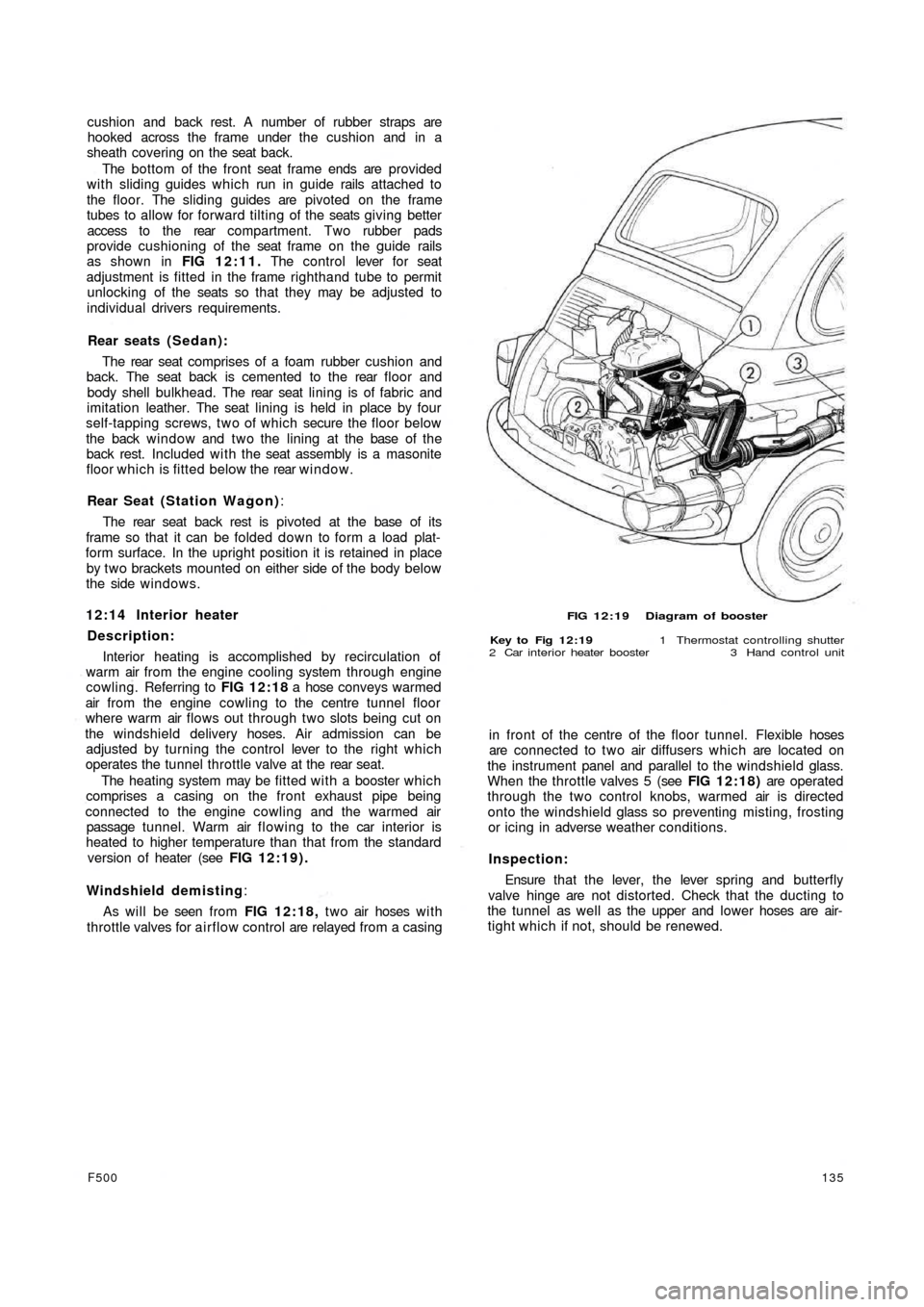
The heating system may be fitted with a booster which
comprises a casing on the front exhaust pipe being
connected to the engine cowling and the warmed air
passage tunnel. Warm air flowing to the car interior is
heated to higher temperature than that from the standard
version of heater (see FIG 12:19).
Windshield demisting:
As will be seen from FIG 12:18, t w o air hoses w i t h
throttle valves for airflow control are relayed from a casing
F500135
FIG 12:19 Diagram of booster
Key to Fig 12:19 1 Thermostat controlling shutter
2 Car interior heater booster 3 Hand control unit
in front of the centre of the floor tunnel. Flexible hoses
are connected to two air diffusers which are located on
the instrument panel and parallel to the windshield glass.
When the throttle valves 5 (see FIG 12:18) are operated
through the two control knobs, warmed air is directed
onto the windshield glass so preventing misting, frosting
or icing in adverse weather conditions.
Inspection:
Ensure that t h e lever, the lever spring and butterfly
valve hinge are not distorted. Check that the ducting to
the tunnel as well as the upper and lower hoses are air-
tight which if not, should be renewed.