ESP FIAT 500 1965 1.G User Guide
[x] Cancel search | Manufacturer: FIAT, Model Year: 1965, Model line: 500, Model: FIAT 500 1965 1.GPages: 128, PDF Size: 9.01 MB
Page 63 of 128
3 Check the layshaft and the primary shaft between
centres and using a dial gauge ensure that there is no
distortion. The out of true reading for bearing seats
should be less than .0008 inch. Inspect the splines and
ensure that the side and outerfaces are not indented.
Replace if there are signs of wear. Also inspect the
reverse shaft to ensure that it is perfectly smooth and
not showing signs of pitting or partial seizure.
4 Carefully inspect all gear teeth for signs of excessive
wear or damage. The contact faces must be smooth and
show no signs of indentation marks. Also check that
the backlash between the gears, when correctly
mounted on the surface plate is not greater than .0039
inch. The maximum wear limit is .0079 inch. Check that
the quick engagement front teeth of the second-, third-
and fourth-speed gears are not damaged or excessively
worn. Renew if there are signs of gearchange lever
misuse.
5 Inspect the sliding sleeves and the relevent hubs, ensure
that all the working surfaces are perfectly smooth. The
clearance between the mating parts should not be
greater than .0059 inch. Also inspect the meshing teeth
and ensure that they are in good condition.
6 Check that the gear shifting selector forks are not dis-
torted and that the striker rods freely slide in their seats
in the gearbox casing.
7 Carefully inspect that all the oil seals are in perfect con-
dition and if there is any doubt they should be renewed.
8 Inspect the striker rod locking balls and the safety rollers
and ensure that they slide freely in their seatings. Also
check the ball load spring efficiency and if this shows
signs of weakness then it should be renewed. Any
faults with these items will cause difficulty in engaging
gears or autodisengagement during engine acceleration.
6 : 4 Reassembly—gearbox
To reassemble the components to the gearbox ensure
that all components are thoroughly clean and then pro-
ceed as follows:
1 Press t h e pinion rear roller bearing onto the layshaft.
Install the layshaft in the casing, and at the same time
fit the adjustment shim, the fourth-speed driven gear
together w i t h its bush, the sleeve and hub for third and
fourth gear engagement, the first-speed and reverse
driven gear and the third-speed driven gear with its
hub.
2 Install the front layshaft ballbearing securing the
bearing retainment plate w i t h the screws and finally
lock the screws in position.
3 Insert the primary shaft together with the first, third
and fourth driving gear train in the gearbox housing
and slide t h e rear bearing onto the shaft. Push the
input shaft forward to enable the clutch shaft coupling
to be inserted in t h e rear and to be pulled up the
primary shaft by means of the pin. Do not forget the
retaining ring.
4 Slide the primary shaft backwards so pushing the rear
bearing into its bore. Refit the front bearing onto the
primary shaft.
5 On the layshaft insert the second-speed driven shaft
and bush, the second gear sliding dog sleeve and the
hub. Also insert the second-speed striker rod and the
first-speed fork. Do not forget to fit the safety roller
into its seating.
70
6 Slide the second-speed driving gear onto the primary
shaft. Place the engagement fork on the third- and
fourth-speed engagement sliding sleeve, and insert
the striker rod, lock the relevent fork and fit the safety
roller.
7 Insert the third safety roller and install the reverse shaft
and insert the reverse gear cluster onto it and secure
the shaft by tightening its block bolt. Install the reverse
striker rod w i t h its relevent fork.
8 Now refit the speedometer drive worm gear onto the
layshraft. Tighten the nuts on the primary shaft and the
layshaft, not forgetting to interpose the plain washer
between the speedometer driving worm and the nut,
to a torque wrench setting of 1 8.1 Ib ft to 25.3 Ib ft
(primary shaft) and 28.9 to 36.2 Ib ft (layshaft). It is
recommended that the input shaft and layshaft are
locked together by engaging t w o gears at the same
time. Finally, fit the splitpins.
9 Lock the shifter forks onto their shafts by tightening
their respective bolts and bend up the special locking
plates. Install the three positioning balls and relevant
springs into their bores and refit the cover plate.
10 Install the casing cover together with its relevant
gasket. This will enable correct positioning of the shift
shaft lever so that it engages in the outer ends of the
shifter shafts protruding from the gearbox casing.
11 Install the speedometer drive support on the gearbox
casing and refit the upper gearbox cover.
For subsequent differential operations and adjustments
see Sections 6:6.
6:5 Dismantling—differential and final drive
For the removal of the differential and final drive unit
from the gearbox refer to Section 6:3. To dismantle the
differential assembly
proceed as follows:
1 Remove the retaining ring 2 (see FIG 6 : 7) retaining
the splined sleeve 4 and slide the sleeve off the drive
shaft.
2 Remove t h e retaining covers 7 and the oil boots all
together with the bushes and seals, adjuster ring lock
rings 13, adjuster rings housing 14, and bearing
adjuster and roller bearing outer races.
3 Separate the differential housing halves by unscrewing
and removing the six bolts that keep both the halves and
the crownwheel together. It is advisable to mark the
respective components to ensure correct matching
upon reassembly.
4 Remove the differential pinion shaft retainer ring, also
the differential pinions 10 by removing the shaft and
withdrawing the two axle shafts 1.
5 Remove the differential side gears 6 and relevent thrust
rings 8.
6 Using a press remove the differential bearing inner
races from their seats on the carrier halves.
7 Thoroughly clean all parts and dry using a compressed
air jet.
Inspection:
The components of the differential unit must be
thoroughly inspected for correct operation and to deter-
mine the presence of any wear, damage or other irregulari-
ties. To check the items concerned proceed as follows:
1 Check thoroughly the idle pinion carrier shaft for signs
Page 67 of 128
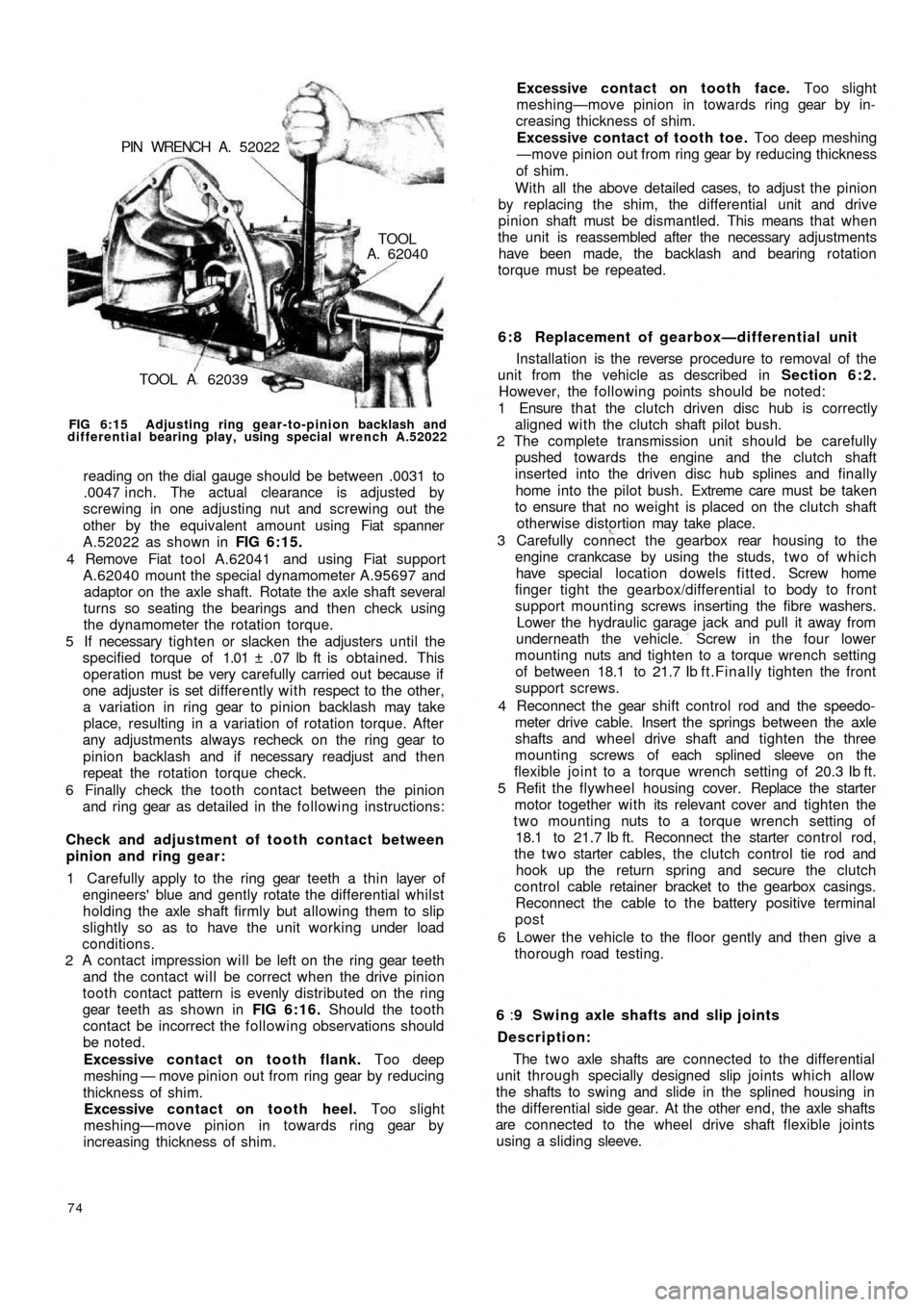
TOOL A 62039
TOOLA. 62040 PIN WRENCH A. 52022
FIG 6:15 Adjusting ring gear-to-pinion backlash and
differential bearing play, using special wrench A.52022
reading on the dial gauge should be between .0031 to
.0047 inch. The actual clearance is adjusted by
screwing in one adjusting nut and screwing out the
other by the equivalent amount using Fiat spanner
A.52022 as shown in FIG 6:15.
4 Remove Fiat tool A.62041 and using Fiat support
A.62040 mount the special dynamometer A.95697 and
adaptor on the axle shaft. Rotate the axle shaft several
turns so seating the bearings and then check using
the dynamometer the rotation torque.
5 If necessary tighten or slacken the adjusters until the
specified torque of 1.01 ± .07 lb ft is obtained. This
operation must be very carefully carried out because if
one adjuster is set differently with respect to the other,
a variation in ring gear to pinion backlash may take
place, resulting in a variation of rotation torque. After
any adjustments always recheck on the ring gear to
pinion backlash and if necessary readjust and then
repeat the rotation torque check.
6 Finally check the tooth contact between the pinion
and ring gear as detailed in the following instructions:
Check and adjustment of tooth contact between
pinion and ring gear:
1 Carefully apply to the ring gear teeth a thin layer of
engineers' blue and gently rotate the differential whilst
holding the axle shaft firmly but allowing them to slip
slightly so as to have the unit working under load
conditions.
2 A contact impression will be left on the ring gear teeth
and the contact will be correct when the drive pinion
tooth contact pattern is evenly distributed on the ring
gear teeth as shown in FIG 6:16. Should the tooth
contact be incorrect the following observations should
be noted.
Excessive contact on tooth flank. Too deep
meshing — move pinion out from ring gear by reducing
thickness of shim.
Excessive contact on tooth heel. Too slight
meshing—move pinion in towards ring gear by
increasing thickness of shim.
74
6 : 8 Replacement of gearbox—differential unit
Installation is the reverse procedure to removal of the
unit from the vehicle as described in Section 6:2.
However, the following points should be noted:
1 Ensure that the clutch driven disc hub is correctly
aligned with the clutch shaft pilot bush.
2 The complete transmission unit should be carefully
pushed towards the engine and the clutch shaft
inserted into the driven disc hub splines and finally
home into the pilot bush. Extreme care must be taken
to ensure that no weight is placed on the clutch shaft
otherwise distortion may take place.
3 Carefully connect the gearbox rear housing to the
engine crankcase by using the studs, t w o of which
have special location dowels fitted. Screw home
finger tight the gearbox/differential to body to front
support mounting screws inserting the fibre washers.
Lower the hydraulic garage jack and pull it away from
underneath the vehicle. Screw in the four lower
mounting nuts and tighten to a torque wrench setting
of between 18.1 to 21.7 Ib f t.Finally tighten the front
support screws.
4 Reconnect the gear shift control rod and the speedo-
meter drive cable. Insert the springs between the axle
shafts and wheel drive shaft and tighten the
three
mounting screws of each splined sleeve on the
flexible joint to a torque wrench setting of 20.3 Ib ft.
5 Refit the flywheel housing cover. Replace the starter
motor together with its relevant cover and tighten the
two mounting nuts to a torque wrench setting of
18.1 to 21.7 Ib ft. Reconnect the starter control rod,
the t w o starter cables, the clutch control tie rod and
hook up the return spring and secure the clutch
control cable retainer bracket to the gearbox casings.
Reconnect the cable to the battery positive terminal
post
6 Lower the vehicle to the floor gently and then give a
thorough road testing.
6 :9 Swing axle shafts and slip joints
Description:
The t w o axle shafts are connected to the differential
unit through specially designed slip joints which allow
the shafts to swing and slide in the splined housing in
the differential side gear. At the other end, the axle shafts
are connected to the wheel drive shaft flexible joints
using a sliding sleeve. Excessive contact on tooth face. Too slight
meshing—move pinion in towards ring gear by in-
creasing thickness of shim.
Excessive contact of tooth toe. Too deep meshing
—move pinion out from ring gear by reducing thickness
of shim.
With all the above detailed cases, to adjust the pinion
by replacing the shim, the differential unit and drive
pinion shaft must be dismantled. This means that when
the unit is reassembled after the necessary adjustments
have been made, the backlash and bearing rotation
torque must be repeated.
Page 73 of 128
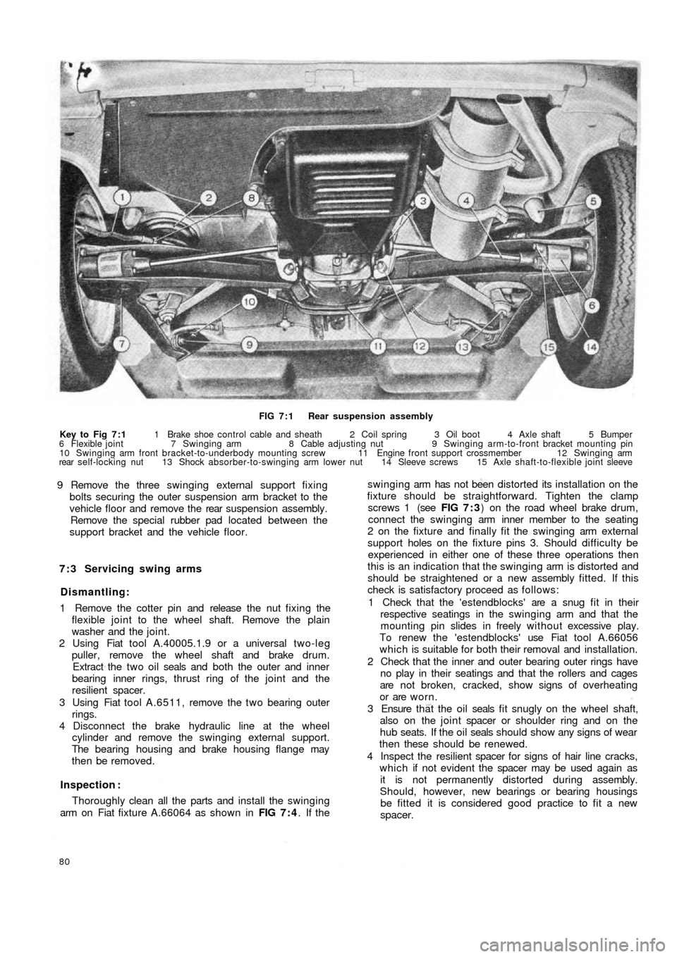
FIG 7 : 1 Rear suspension assembly
Key to Fig 7 : 1 1 Brake shoe control cable and sheath 2 Coil spring 3 Oil boot 4 Axle shaft 5 Bumper
6 Flexible joint 7 Swinging arm 8 Cable adjusting nut 9 Swinging arm-to-front bracket mounting pin
10 Swinging arm front bracket-to-underbody mounting screw 11 Engine front support crossmember 12 Swinging arm
rear self-locking nut 13 Shock absorber-to-swinging arm lower nut 14 Sleeve screws 15 Axle shaft-to-flexible joint sleeve
9 Remove the three swinging external support fixing
bolts securing the outer suspension arm bracket to the
vehicle floor and remove the rear suspension assembly.
Remove the special rubber pad located between the
support bracket and the vehicle floor.
7 : 3 Servicing swing arms
Dismantling:
1 Remove the cotter pin and release the nut fixing the
flexible joint to the wheel shaft. Remove the plain
washer and the joint.
2 Using Fiat tool A.40005.1.9 or a universal two-leg
puller, remove the wheel shaft and brake drum.
Extract the t w o oil seals and both the outer and inner
bearing inner rings, thrust ring of the joint and the
resilient spacer.
3 Using Fiat tool A.6511, remove the t w o bearing outer
rings.
4 Disconnect the brake hydraulic line at the wheel
cylinder and remove the swinging external support.
The bearing housing and brake housing flange may
then be removed.
Inspection :
Thoroughly clean all the parts and install the swinging
arm on Fiat fixture A.66064 as shown in FIG 7 : 4. If the
80
swinging arm has not been distorted its installation on the
fixture should be straightforward. Tighten the clamp
screws 1 (see FIG 7 : 3) on the road wheel brake drum,
connect the swinging arm inner member to the seating
2 on the fixture and finally fit the swinging arm external
support holes on the fixture pins 3. Should difficulty be
experienced in either one of these three operations then
this is an indication that the swinging arm is distorted and
should be straightened or a new assembly fitted. If this
check is satisfactory proceed as follows:
1 Check that the 'estendblocks' are a snug fit in their
respective seatings in the swinging arm and that the
mounting pin slides in freely w it h ou t excessive play.
To renew the 'estendblocks' use Fiat tool A.66056
which is suitable for both their removal and installation.
2 Check that the inner and outer bearing outer rings have
no play in their seatings and that the rollers and cages
are not broken, cracked, show signs of overheating
or are worn.
3 Ensure t h a t the o i l seals f i t snugly on the wheel shaft,
also on the joint spacer or shoulder ring and on the
hub seats. If the oil seals should show any signs of wear
then these should be renewed.
4 Inspect the resilient spacer for signs of hair line cracks,
which if not evident the spacer may be used again as
it is not permanently distorted during assembly.
Should, however, new bearings or bearing housings
be fitted it is considered good practice to fit a new
spacer.
Page 76 of 128
high bearing preload. To reset remove the wheel shaft
and fit a new resilient spacer. Repeat the rotation
torque test.
Swinging arm adjustment:
To adjust the swinging arm use Fiat fixture A.66064 as
shown in FIG 7 : 3 and proceed as follows:
1 At points A and B as indicated in FIG 7 : 4 between the
'estendblock' and the swinging arm to body front
mounting bracket fit three shims on each side. To
ensure that the shims are correctly centred use Fiat
alignment bar A.66057.
2 Whilst removing the alignment bar, carefully slip in the
mounting pin and screw on the nut. Once the rear
wheel geometry adjustment has been completed this
nut should be tightened to a torque wrench setting
of 43.4 to 50.6 Ib ft.
3 At points C and D (see FIG 7 : 4) , insert the number of
shims required to fill in the gap between the 'estend-
block' and the two fixture shoulders. Having deter-
mined the number of shims required both at locations
C and D, these must later be fitted between the
'estendblock' and the shoulders on the swinging arm
to body mounting bracket.
7 : 4 Coil springs
The coil springs should be thoroughly cleaned and all
traces of rust removed. Inspect the spring coils for hair
line cracks, which if evident, a new pair of springs must
be fitted to ensure correct vehicle height and stability.
Check the free
height and the height under loading of
the coil springs and these must correspond to the figures
quoted in Technical Data.
7:5 Installation of rear suspension assembly
To replace the rear suspension assembly proceed as
follows:
1 Insert the swinging arm inner end in the mounting
bracket which is welded onto the body floor. Place
between the 'estendblock' and bracket the number of
adjustment shims as previously determined using Fiat
fixture A.66064 as shown in FIG 7 : 4. Insert the Fiat
alignment bar A.66057 through 'estendblock' and
shims, aligning them with the holes in the mounting
bracket. Firmly hold the entire assembly using a garage
hydraulic jack if necessary, and carefully remove the
alignment bar and at the same time ease in t h e
mounting pin. Secure the nut which once the rear
wheels geometry has been checked must be tightened
to a torque wrench setting of 43.4 to 50.6 Ib/ft.
2 Screw in finger tight the three swinging arm external
bracket to body floor mounting screws together w i t h
the plain and spring washers. The screws will have to
be tightened to a torque wrench setting of 28.9 to
36.2 Ib/ft once the rear wheel geometry has been
adjusted.
3 Carefully insert the coil spring, lower insulator ring
onto the swinging arm, insert the spring on the shock
absorber which should be previously secured to the
arm and position the spring onto its seat on the arm.
Place the upper insulator ring onto the spring, raise the
suspension assembly using a garage hydraulic jack and
insert the spring onto its seating under the body floor.
F50083 4 Ensure that the shock absorber to floor rubber ring has
been correctly fitted and extend the shock absorber
until its upper mounting pin protrudes into the vehicle
through the hump in the floor panel. Secure the shock
absorber by its mounting nut and lockwasher having
first inserted the rubber ring and plain washer.
5 Refit the rear wheel housing in place, reconnect the
brake line to the connection on body floor and remove
the plug from the output hole in the brake fluid
reservoir. Bleed the hydraulic brake system as
described in Chapter 10.
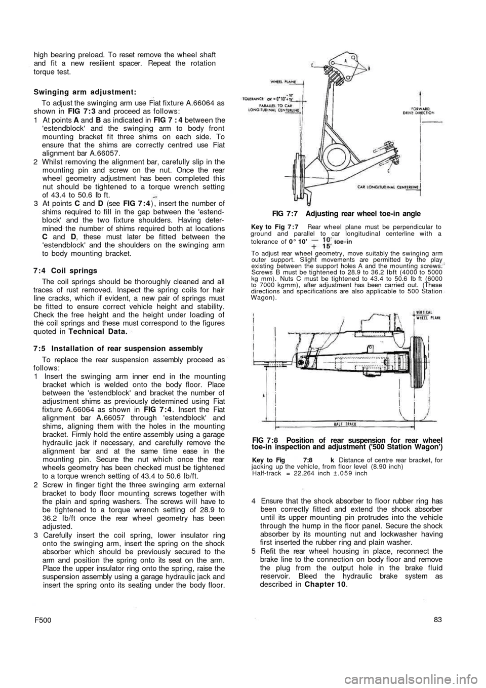
Key to Fig 7:8 k Distance of centre rear bracket, for
jacking up the vehicle, from floor level (8.90 inch)
Half-track = 22.264 inch ±.059 inch
FIG 7 : 8 Position of rear suspension f o r rear wheel
toe-in inspection and adjustment ('500 Station Wagon') FIG 7 : 7 Adjusting rear wheel toe-in angle
Key to Fig 7 : 7 Rear wheel plane must be perpendicular to
ground and parallel to car longitudinal centerline with a
tolerance of 0° 10'
To adjust rear wheel geometry, move suitably the swinging arm
outer support. Slight movements are permitted by the play
existing between the support holes A and the mounting screws.
Screws B must be tightened to 28.9 to 36.2 Ibft (4000 to 5000
kg mm). Nuts C must be tightened to 43.4 to 50.6 Ib ft (6000
to 7000 kgmm), after adjustment has been carried out. (These
directions and specifications are also applicable to 500 Station
Wagon).
Page 97 of 128
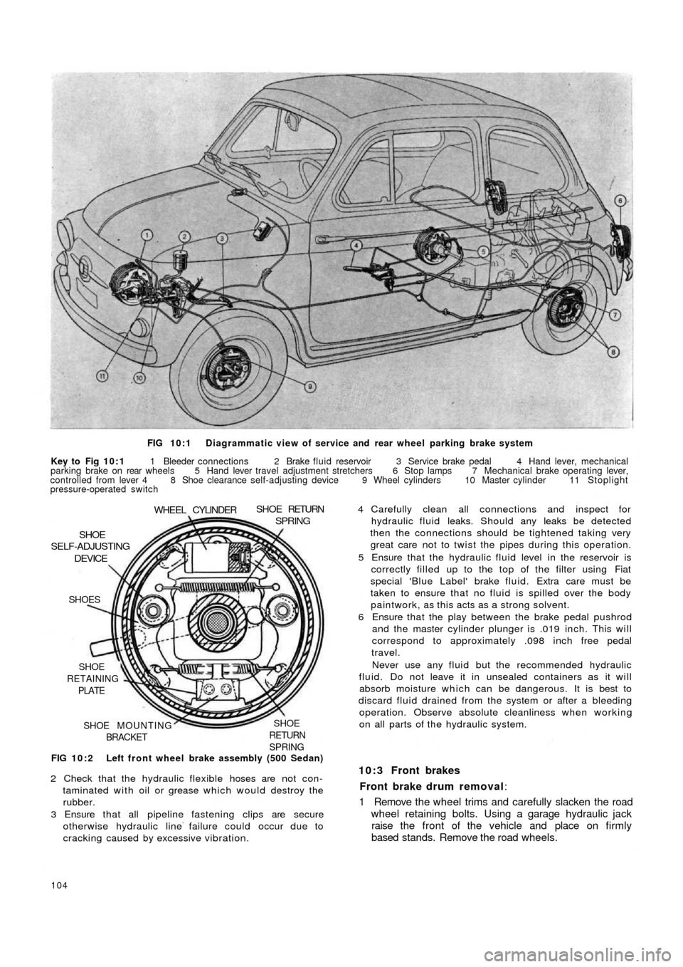
FIG 10:1 Diagrammatic view of service and rear wheel parking brake system
Key to Fig 10:1 1 Bleeder connections 2 Brake fluid reservoir 3 Service brake pedal 4 Hand lever, mechanical
parking brake on rear wheels 5 Hand lever travel adjustment stretchers 6 Stop lamps 7 Mechanical brake operating lever,
controlled from lever 4 8 Shoe clearance self-adjusting device 9 Wheel cylinders 10 Master cylinder 11 Stoplight
pressure-operated switch
FIG 10:2 Left front wheel brake assembly (500 Sedan)
SHOE
RETURN
SPRINGSHOE MOUNTING
BRACKET SHOE
RETAINING
PLATE SHOES
DEVICESHOE
SELF-ADJUSTING
WHEEL CYLINDERSHOE RETURNSPRING
2 Check that the hydraulic flexible hoses are not con-
taminated with oil or grease which would destroy the
rubber.
3 Ensure that all pipeline fastening clips are secure
otherwise hydraulic line failure could occur due to
cracking caused by excessive vibration.
104
4 Carefully clean all connections and inspect for
hydraulic fluid leaks. Should any leaks be detected
then the connections should be tightened taking very
great care not to twist the pipes during this operation.
5 Ensure that the hydraulic fluid level in the reservoir is
correctly filled up to the top of the filter using Fiat
special 'Blue Label' brake fluid. Extra care must be
taken to ensure that no fluid is spilled over the body
paintwork, as this acts as a strong solvent.
6 Ensure that the play between the brake pedal pushrod
and the master cylinder plunger is .019 inch. This will
correspond to approximately .098 inch free pedal
travel.
Never use any fluid but the recommended hydraulic
fluid. Do not leave it in unsealed containers as it will
absorb moisture which can be dangerous. It is best to
discard fluid drained from the system or after a bleeding
operation. Observe absolute cleanliness when working
on all parts of the hydraulic system.
10:3 Front brakes
Front brake drum removal:
1 Remove the wheel trims and carefully slacken the road
wheel retaining bolts. Using a garage hydraulic jack
raise the front of the vehicle and place on firmly
based stands. Remove the road wheels.
Page 101 of 128
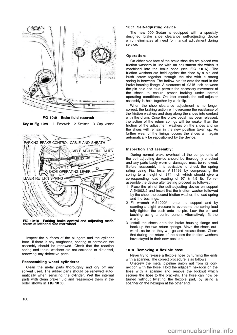
FIG 10:9 Brake fluid reservoir
Key to Fig 1 0 : 9 1 Reservoir 2 Strainer 3 Cap, vented
PARKING BRAKE CONTROL CABLE AND SHEATH
.CABLE ADJUSTING NUTS
SHOE OPERATING LEVER
LEVER RETURN SPRING
FIG 10:10 Parking brake control and adjusting mech-
anism at lefthand side rear wheel
Inspect the surfaces of the plungers and the cylinder
bore. If there is any roughness, scoring or corrosion the
assembly should be renewed. Check that the reaction
spring and thrust washers are not corroded or distorted,
renewing any defective parts.
Reassembling wheel cylinders:
Clean the metal parts thoroughly and dry off any
solvent used. The rubber parts should be renewed auto-
matically when servicing the cylinder. Wet the internal
parts w i t h clean brake f l u i d and reassemble them in the
order shown in FIG 10 : 8 .
10810:7 Self-adjusting device
The new 500 Sedan is equipped with a specially
designed brake shoe clearance self-adjusting device
which eliminates all need for manual adjustment during
service.
Operation:
On either side face of the brake shoe rim are placed t w o
friction washers in line with an adjustment slot which is
machined into the brake shoe (see FIG 10:6). The
friction washers are held against the shoe by a pin and
bush screw together through the slot with a strong
spring in between. The hollow pin fits onto the stud in the
brake housing flange. A clearance of .0315 inch between
the pin hole and stud permits the necessary movement of
the shoes to ensure proper braking under normal
operating conditions. On later models the self-adjuster
assembly is held together by a circlip.
When the shoe clearance adjustment is no longer
correct, the braking action will overcome the resistance of
the friction washers and drag along the shoes into contact
with the drum. Once the brake pedal has been released,
the action of the return springs will be weaker than the
friction of the adjustment washers on the shoes and so
the shoes will remain in the new position taken up. As
further wear of the linings occurs the shoes will again
automatically be repositioned by the device.
Inspection and assembly:
During normal brake overhaul all the components of
the self-adjusting device should be thoroughly checked
and any parts badly worn or damaged must be renewed.
Before reassembly it is advisable to check the spring
rating using Fiat tester A.11493 by
compressing the
spring to a height of .374 inch which should give a
corresponding load reading of 97 ± 4.9 Ib. To re-
assemble the device after testing proceed as follows:
1 Place the pin of the self-adjusting device on support
A.54002/2 and insert first the friction washer followed
by the shoe, the second friction washer, the load spring
and the bushings.
2 Fit wrench A.54002/1 onto the support and by
exerting a slight pressure to overcome the spring load
fully tighten the bush onto the pin. Lock the pin and
bushing using a centre punch. Alternatively, fit the
circlip.
3 Install the shoes onto the brake housing flange and
hook up the t w o return springs. Move the shoes out-
wards as far as they will go and release them. Check
that during the return of the shoes the friction washers
have stayed in their new position.
10:8 Removing a flexible hose
Never try to release a flexible hose by turning the ends
w i t h a spanner. The correct procedure is as follows:
Unscrew the metal pipeline union nut from its con-
nection with the hose. Hold the adjacent hexagon on the
hose w i t h a spanner and remove the locknut which
secures the hose to the brackets. The hose can now be
turned without twisting the flexible part, by using a
spanner on the hexagon at the other end.
1
2
3
Page 104 of 128
CHAPTER 11
THE ELECTRICAL EQUIPMENT
11:1 Description
11:2 Battery
11:3 The generator
11:4 The starter
11:5 The control box
1 1 : 6 Fuses
1 1 : 7 Flasher unit
11:1 Description
All models covered by this manual have 12 volts
electrical systems in which the negative battery terminal
is earthed. There are three units in the regulator box to
control the charging circuit; a cut-out, a current regulator
and a voltage regulator. These are adjustable but it must
be stressed that accurate moving coil meters are required
when checking or altering the settings. Cheap and
unreliable instruments will make accurate adjustments
impossible.
There are wiring diagrams in Technical Data at the end
of this manual to enable those with electrical experience
to trace and correct wiring faults.
For t h e U.K. Market the headlamps are of the double
filament dipping renewable bulb type with adjustments
for individual beam settings.
The battery is located in the front compartment
forward of the petrol tank and the fuses to the rear o f the
petrol tank.
Detailed instructions for servicing the electrical equip-
ment will be found in this chapter, but it must be pointed
out that it is not sensible to try to repair that which is
seriously defective, electrically or mechanically. Such
equipment should be replaced by new units which can
be obtained on an exchange basis.
F500111
11 :8 Windscreen wipers
1 1 : 9 The lighting system
11:10 Panel and warning lights
11:11 The horn
11:12 Lighting and flasher switch
1 1 : 1 3 Fault diagnosis
11.2 The battery
This of the 12-volt lead/acid type and has to meet
heavy demands for current particularly in the winter. To
maintain the performance of the battery at its maximum
it is essential to carry out the following operations.
Keep the top of the battery and surrounding parts dry
and clean, as dampness can cause leakage between the
securing clamps and the battery terminals. Clean off any
corrosion from the metal parts of the battery mounting
with diluted ammonia and paint them with an anti-
sulphuric paint. If the terminal posts are corroded,
remove the cables and clean w i t h diluted ammonia.
Smear the posts w i t h petroleum jelly before remaking the
connections and fit the terminals securely. High electrical
resistance due to corrosion at the terminal posts is often
responsible for lack of sufficient current to operate the
starter motor.
Ensure t h a t the filler plugs are in good condition and
show no signs of cracks. This may cause leakage of
electrolyte and consequent corrosion. Test the condition
of the cells after topping-up the electrolyte level with
distilled water to just above the tops of the separators as
shown in FIG 11 :2 . Never add neat acid. If it is
necessary to make a new electrolyte due to loss by
spillage add sulphuric acid to the
distilled water.
It is highly dangerous to add water to acid.
Page 110 of 128
Checking cut-out:
1 Closing voltage:
This test should be carried out at a temperature of
25°±10°C and the regulator should be connected to a
generator test bed as shown in FIG 11:7. The unit should
be operated under no load conditions for between 15 -
18 minutes with the cover installed and w i t h a voltage of
between 16.5 volts for an initial operating temperature of
15-20°C or 15 volts for an initial operating temperature
of 20-35°C. This will enable thermal stabilization of the
unit to be obtained so that the temperature of both the
cut-out shunt windings and the bymetallic springs
increase due to the heat developed by the windings and
reaches the normal operating setting.
Once thermal stabilization has been obtained the
generator should be restarted and the speed gradually
increased so that immediately the test lamp starts to
glow the voltmeter reading may be taken. This will be
the value of the cut-out contact closing voltage.
2 Reverse current:
This check should be carried out at a temperature range
of between 25°±10°C and it is recommended that it is
performed as soon as possible after the closing voltage
test so that the thermal stabilization remains unaltered.
Connect the regulator as shown in FIG 11:8 and
gradually speed up the generator to 4500 rev/min for
approximately 5 minutes. Ensure that the voltmeter reads
at least 14.5 volts and then gradually reduce the generator
speed carefully watching the movement of the ammeter
needle which should at first indicate a charging current
and then gradually move to zero and then to the other side
of the scale to indicate reverse current value. If the
generator speed is reduced further the reverse current
reading will increase to a given value and then suddenly
fall to zero which will indicate that the cut-out contact
has opened. This limit indicates the maximum reverse
current value which should not, under any circumstances,
exceed 16 amps.
During this test, to obtain the maximum reverse
current possible the reduction in generator speed must
not take more than 10 seconds otherwise the battery
voltage will drop excessively.
Checking voltage regulator:
This test should be carried out w i t h the regulator under
half load and at a temperature of 50°± 3°C. Connect the
regulator as shown in FIG 11:9 and operate the regulator
for approximately 30 minutes by supplying a current half
that of regulated current which is 1 6 ±5 amp. Once the
regulator has been brought to the required temperature
stop the generator and start it again, gradually increasing
the speed to a maximum of 4500 rev/min. Adjust the
rheostat for a generator output corresponding to half load
current of 8 ± 2 amps. When this generator output has
been set the voltage should be 14.2± .3 volts.
Checking current regulator:
Leave the regulator connected as shown in
FIG 11 :10
and this test must be carried out immediately after testing
the half load regulated voltage of the voltage regulator
when connected to a battery. Check that the ammeter
fitted will accommodate a 40 amp deflection: if not a
F500117
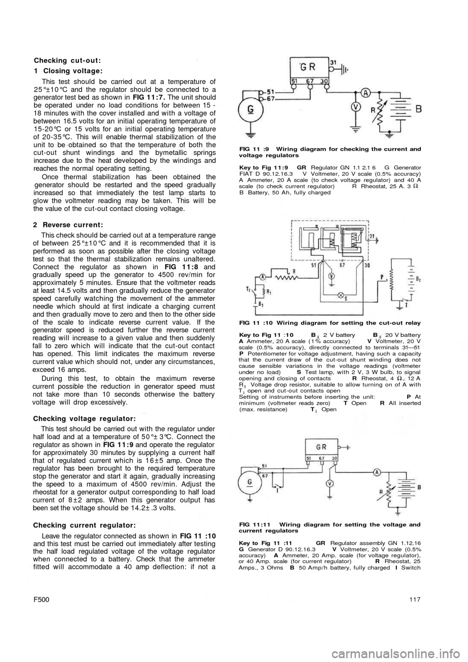
FIG 11 :9 Wiring diagram for checking the current and
voltage regulators
Key to Fig 11:9 GR Regulator GN 1.1 2.1 6 G Generator
FIAT D 90.12.16.3 V Voltmeter, 20 V scale (0.5% accuracy)
A Ammeter, 20 A scale (to check voltage regulator) and 40 A
scale (to check current regulator)
B Battery, 50 Ah, fully chargedR Rheostat, 25 A. 3
FIG 11 :10 Wiring diagram for setting the cut-out relay
Key to Fig 11 :10 B 2 V battery B 20 V batteryA Ammeter, 20 A scale ( 1 % accuracy) V Voltmeter, 20 V
scale (0.5% accuracy), directly connected to terminals 31—51
P Potentiometer for voltage adjustment, having such a capacity
that the current draw of the cut-out shunt winding does not
cause sensible variations in the voltage readings (voltmeter
under no load) S Test lamp, with 2 V, 3 W bulb, to signal
opening and closing of contacts R Rheostat, 4 12
AR Voltage drop resistor, suitable to allow turning on of A withT open and cut-out contacts open
Setting of instruments before inserting the unit: P At
minimum (voltmeter reads zero) T Open R All inserted
(max. resistance) T Open
FIG 11:11 Wiring diagram for setting the voltage and
current regulators
Key to Fig 11 :11 GR Regulator assembly GN 1.12.16
G Generator D 90.12.16.3 V Voltmeter, 20 V scale (0.5%
accuracy) A Ammeter, 20 Amp. scale (for voltage regulator),
or 40 Amp. scale (for current regulator) R Rheostat, 25
Amps., 3 Ohms B 50 Amp/h battery, fully charged I Switch
Page 111 of 128
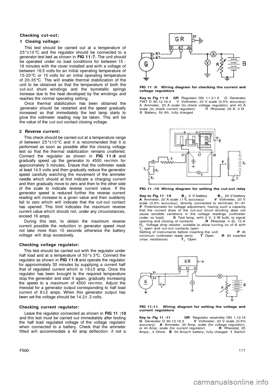
Checking cut-out:
1 Closing voltage:
This test should be carried out at a temperature of
25°±10°C and the regulator should be connected to a
generator test bed as shown in FIG 11:7. The unit should
be operated under no load conditions for between 15 -
18 minutes with the cover installed and w i t h a voltage of
between 16.5 volts for an initial operating temperature of
15-20°C or 15 volts for an initial operating temperature
of 20-35°C. This will enable thermal stabilization of the
unit to be obtained so that the temperature of both the
cut-out shunt windings and the bymetallic springs
increase due to the heat developed by the windings and
reaches the normal operating setting.
Once thermal stabilization has been obtained the
generator should be restarted and the speed gradually
increased so that immediately the test lamp starts to
glow the voltmeter reading may be taken. This will be
the value of the cut-out contact closing voltage.
2 Reverse current:
This check should be carried out at a temperature range
of between 25°±10°C and it is recommended that it is
performed as soon as possible after the closing voltage
test so that the thermal stabilization remains unaltered.
Connect the regulator as shown in FIG 11:8 and
gradually speed up the generator to 4500 rev/min for
approximately 5 minutes. Ensure that the voltmeter reads
at least 14.5 volts and then gradually reduce the generator
speed carefully watching the movement of the ammeter
needle which should at first indicate a charging current
and then gradually move to zero and then to the other side
of the scale to indicate reverse current value. If the
generator speed is reduced further the reverse current
reading will increase to a given value and then suddenly
fall to zero which will indicate that the cut-out contact
has opened. This limit indicates the maximum reverse
current value which should not, under any circumstances,
exceed 16 amps.
During this test, to obtain the maximum reverse
current possible the reduction in generator speed must
not take more than 10 seconds otherwise the battery
voltage will drop excessively.
Checking voltage regulator:
This test should be carried out w i t h the regulator under
half load and at a temperature of 50°± 3°C. Connect the
regulator as shown in FIG 11:9 and operate the regulator
for approximately 30 minutes by supplying a current half
that of regulated current which is 1 6 ±5 amp. Once the
regulator has been brought to the required temperature
stop the generator and start it again, gradually increasing
the speed to a maximum of 4500 rev/min. Adjust the
rheostat for a generator output corresponding to half load
current of 8 ± 2 amps. When this generator output has
been set the voltage should be 14.2± .3 volts.
Checking current regulator:
Leave the regulator connected as shown in
FIG 11 :10
and this test must be carried out immediately after testing
the half load regulated voltage of the voltage regulator
when connected to a battery. Check that the ammeter
fitted will accommodate a 40 amp deflection: if not a
F500117
FIG 11 :9 Wiring diagram for checking the current and
voltage regulators
Key to Fig 11:9 GR Regulator GN 1.1 2.1 6 G Generator
FIAT D 90.12.16.3 V Voltmeter, 20 V scale (0.5% accuracy)
A Ammeter, 20 A scale (to check voltage regulator) and 40 A
scale (to check current regulator)
B Battery, 50 Ah, fully chargedR Rheostat, 25 A. 3
FIG 11 :10 Wiring diagram for setting the cut-out relay
Key to Fig 11 :10 B 2 V battery B 20 V batteryA Ammeter, 20 A scale ( 1 % accuracy) V Voltmeter, 20 V
scale (0.5% accuracy), directly connected to terminals 31—51
P Potentiometer for voltage adjustment, having such a capacity
that the current draw of the cut-out shunt winding does not
cause sensible variations in the voltage readings (voltmeter
under no load) S Test lamp, with 2 V, 3 W bulb, to signal
opening and closing of contacts R Rheostat, 4 12
AR Voltage drop resistor, suitable to allow turning on of A withT open and cut-out contacts open
Setting of instruments before inserting the unit: P At
minimum (voltmeter reads zero) T Open R All inserted
(max. resistance) T Open
FIG 11:11 Wiring diagram for setting the voltage and
current regulators
Key to Fig 11 :11 GR Regulator assembly GN 1.12.16
G Generator D 90.12.16.3 V Voltmeter, 20 V scale (0.5%
accuracy) A Ammeter, 20 Amp. scale (for voltage regulator),
or 40 Amp. scale (for current regulator) R Rheostat, 25
Amps., 3 Ohms B 50 Amp/h battery, fully charged I Switch
Page 112 of 128
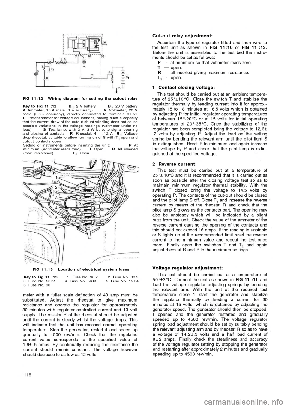
FIG 11:12 Wiring diagram for setting the cutout relay
Key to Fig 11 :12 B 2 V battery B 20 V battery
A Ammeter, 15 A scale ( 1 % accuracy) V Voltmeter, 20 V
scale (0.5% accuracy), directly connected to terminals 31-51
P Potentiometer for voltage adjustment, having such a capacity
that the current draw of the cutout shunt winding does not cause
sensible variations in the voltage readings (voltmeter under no
load) S Test lamp, with 2 V, 3 W bulb, to signal opening
and closing of contacts R Rheostat, 4 , 1 2 A R Voltagedrop rheostat, suitable to allow turning on of S with T open and
cutout contacts open
Setting of instruments before inserting the unit: P At
minimum (Voltmeter reads zero) T Open R All inserted
(max. resistance) T Open
1
2
3
4
5
6
FIG 11:13 Location of electrical system fuses
Key to Fig 11 :13 1 Fuse N o . 30.2 2 Fuse N o . 30.3
3 Fuse N o . 56.b1 4 Fuse N o . 56.b2 5 Fuse N o . 15.54
6 Fuse N o . 30
meter w i t h a fuller scale deflection of 40 amp must be
substituted. Adjust the rheostat to give maximum
resistance and operate the regulator for approximately
30 minutes with regulator controlled current and 13 volt
supply. The resistor R of the rheostat should be adjusted
until the current is steady whilst the voltage drops. This
will indicate that the unit has reached normal operating
temperature. Stop the generator, restart it and speed up
gradually to 4500 rev/min. Check that the regulated
current value corresponds to the specified value of
1 6± .5 amps. By continually reducing the resistance the
current should remain constant. The voltage however
should decrease to as l o w as 12 volts.
118
Cut-out relay adjustment:
Ascertain the type of regulator fitted and then wire to
the test unit as shown in FIG 11:10 or FIG 11 :12.
Before the unit is assembled to the test bed the instru-
ments should be set as follows:
P - at minimum so that voltmeter reads zero.
T — open.
R - all inserted giving maximum resistance.
T - open.
1 Contact closing voltage:
This test should be carried out at an ambient tempera-
ture of 25°±10°C. Close the switch T and stabilize the
regulator thermally by feeding current into it for approxi-
mately 15 to 18 minutes at 16.5 volts which is obtained
by adjusting P for initial regulator operating temperatures
of between 15°-20°C or at 15 volts for initial operating
temperatures of 20°-35°C. Once the stabilizing of the
regulator has been completed bring the voltage to 12 6±
.2 volts by adjusting P. Adjust the load on the setting
spring by bending the relevant arm until the pilot light S
is extinguished. Reset P to m inimum and again increase
the voltage by P and check that the pilot lamp is extin-
guished at the specified voltage.
2 Reverse current:
This test must be carried out at a temperature of
25°± 10°C and it is recommended that it is carried out as
soon as possible after the closing voltage test so as to
maintain minimum regulator thermal stability. With the
switch T closed bring the voltage to 14.5 volts by
operating P. The contacts of the cut-out should be closed
and the pilot lamp S off. Close T and increase the reverse
current by means of the rheostat R and check that the
pilot lamp S glows as the contacts part. The opening may
also be unsteady which will be indicated by a slight
buzz from the unit. Check the value of the ammeter of the
reverse current causing the opening of the contacts and
this should not exceed 16 amps. If the reading is unstable
or S lights up at the recommended limit reset the reverse
current to the minimum value and repeat the test once
more. Finally open the switches T and T and again
adjust rheostat R and P to the minimum settings.
Voltage regulator adjustment:
This test should be carried out at a temperature of
5 0 ° ±3 ° C . Connect the unit as shown in FIG 11 :11 and
load the voltage regulator adjusting springs by bending
the relevant arm. With the unit at the required test
temperature close 1 start the generator and stabilize
the regulator thermally by feeding a current for 30
minutes at 15 volts, which is obtained by adjusting the
generator speed. The generator should then be stopped,
I opened and the generator restarted and gradually
speeded up to 4500 rev/min. The voltage regulator
spring load adjustment should be set by suitably bending
the relevant adjusting arm and by rheostat R so as to have
a voltage of 14.2±.3 volts and a half load current of
8 ± 2 amps. Finally check the steadiness and accuracy
of the voltage regulator setting by stopping the generator
and restarting after approximately 2 minutes and gradually
speeding up to 4500 rev/min.